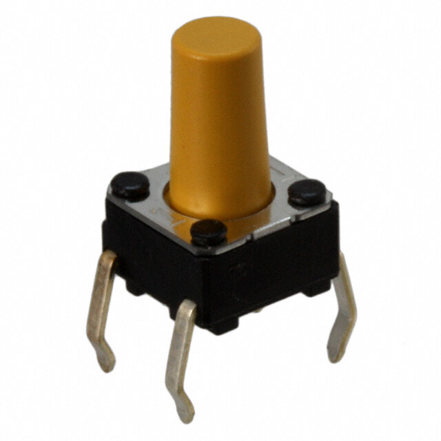
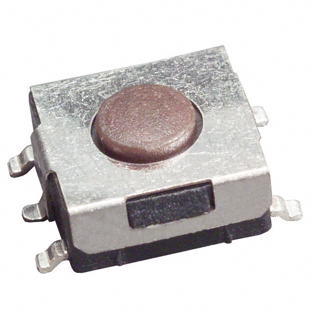
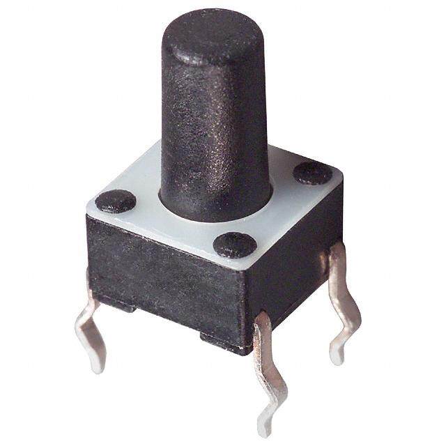
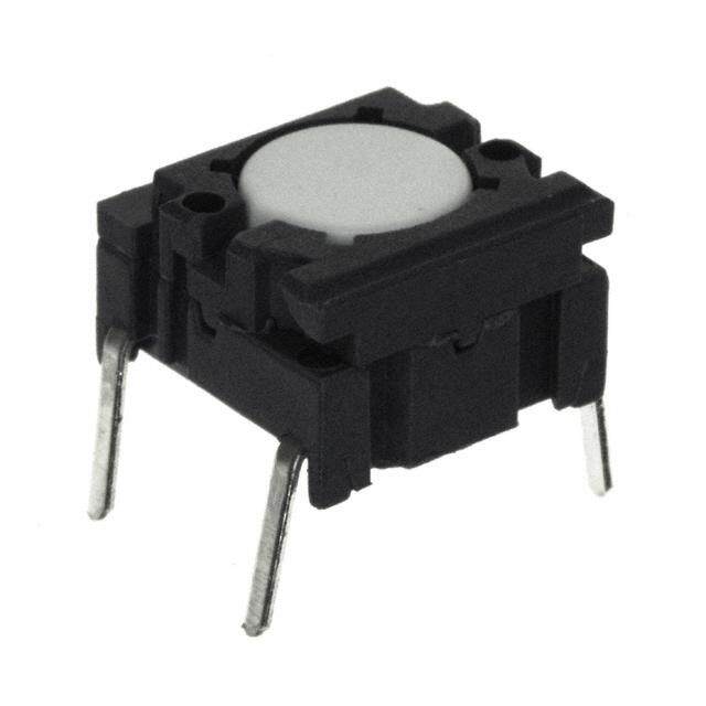
- 型号: EVP-AA702W
- 制造商: Panasonic Corporation
- 库位|库存: xxxx|xxxx
- 要求:
| 数量阶梯 | 香港交货 | 国内含税 |
| +xxxx | $xxxx | ¥xxxx |
查看当月历史价格
查看今年历史价格
EVP-AA702W产品简介:
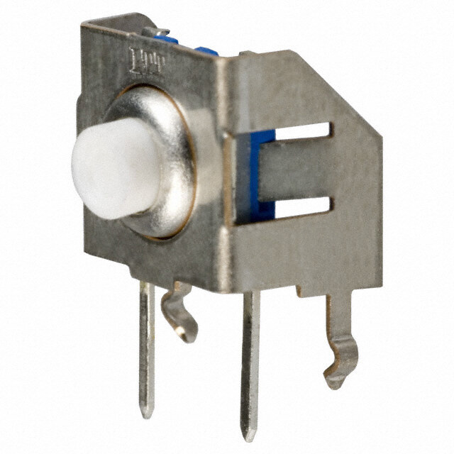
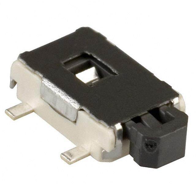
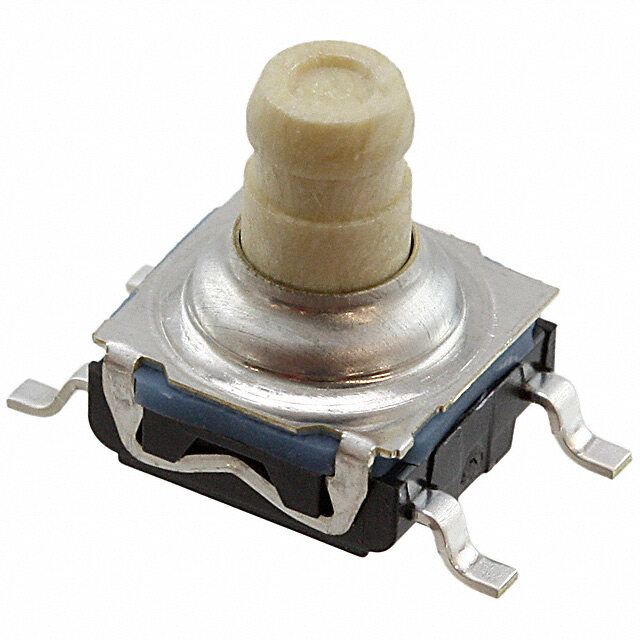
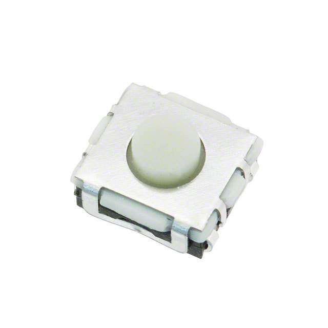
ICGOO电子元器件商城为您提供EVP-AA702W由Panasonic Corporation设计生产,在icgoo商城现货销售,并且可以通过原厂、代理商等渠道进行代购。 EVP-AA702W价格参考。Panasonic CorporationEVP-AA702W封装/规格:触摸开关, 顶部触动 触摸开关 SPST-NO 表面贴装。您可以下载EVP-AA702W参考资料、Datasheet数据手册功能说明书,资料中有EVP-AA702W 详细功能的应用电路图电压和使用方法及教程。
| 参数 | 数值 |
| 3D型号 | http://industrial.panasonic.com/ww/i_e/00000/3d_download_e/3d_download_e.html#acEVPAA |
| 产品目录 | |
| 描述 | SWITCH TACTILE SPST-NO 0.02A 15V触觉开关 Swtch Lite Touch SMD 1.7mm ht J-bent 3.5N |
| 产品分类 | |
| 品牌 | Panasonic |
| 产品手册 | |
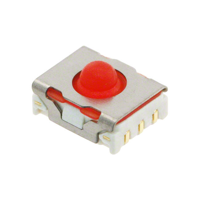
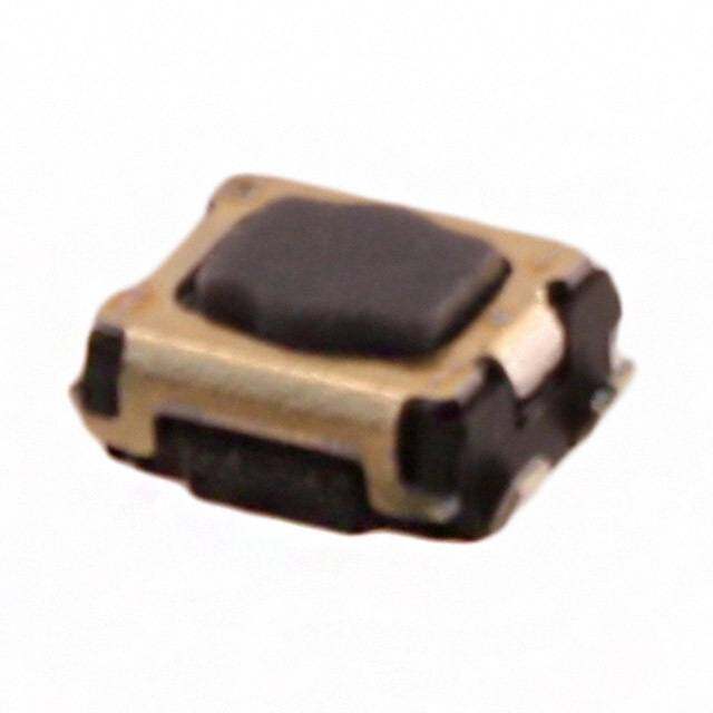
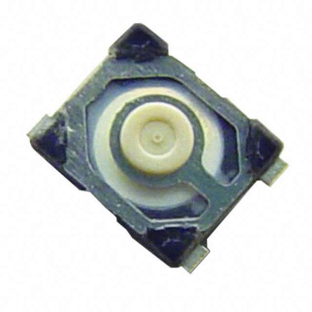
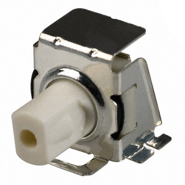
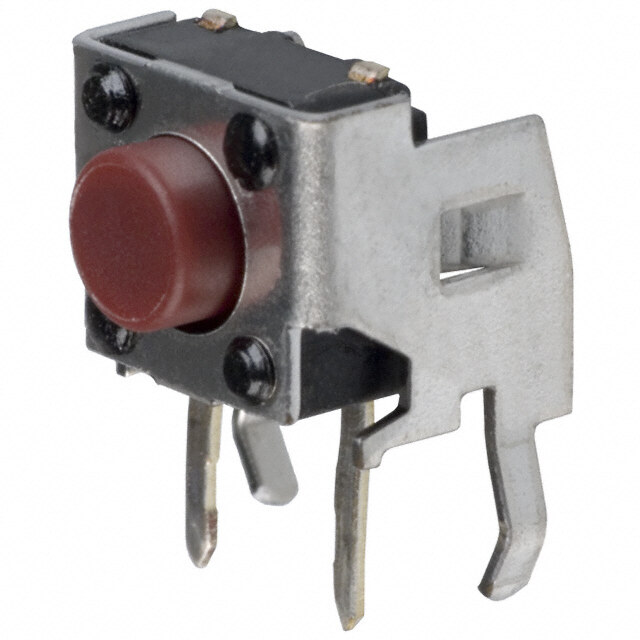
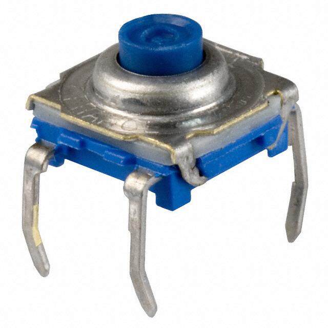
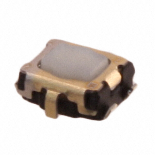
| 产品图片 |
|
| rohs | 符合RoHS无铅 / 符合限制有害物质指令(RoHS)规范要求 |
| 产品系列 | 触觉开关,Panasonic EVP-AA702WEVPAA |
| mouser_ship_limit | 该产品可能需要其他文件才能进口到中国。 |
| 数据手册 | |
| 产品型号 | EVP-AA702W |
| PCB外致动器高度(从引脚计算) | 1.70mm |
| 不同电压时的触头额定电流 | 0.02A @ 15VDC |
| 产品种类 | 触觉开关 |
| 作用力 | 350gf |
| 侵入防护 | - |
| 其它名称 | P15194CT |
| 包装 | 剪切带 (CT) |
| 商标 | Panasonic |
| 外形 | 3.50mm x 2.90mm |
| 安装类型 | 表面贴装 |
| 安装风格 | SMD/SMT |
| 封装 | Reel |
| 工作力 | 3.5 N |
| 工作温度 | -40°C ~ 85°C |
| 工厂包装数量 | 5000 |
| 开关功能 | 关-瞬时 |
| 开关行程 | 0.15mm |
| 接地端子 | Yes |
| 机械寿命 | 200,000 次循环 |
| 标准包装 | 1 |
| 照明 | 不发光 |
| 照明电压(标称值) | - |
| 照明类型,颜色 | - |
| 特性 | 接地引脚 |
| 电压额定值DC | 15 V |
| 电流额定值 | 20 mA |
| 电路 | SPST-NO |
| 端子类型 | J 引线 |
| 端接类型 | Gull Wing Lead |
| 系列 | EVPAA |
| 致动器方向 | 顶部触动 |
| 致动器材料 | - |
| 致动器类型 | 标准 |
| 触点形式 | SPST |


- 商务部:美国ITC正式对集成电路等产品启动337调查
- 曝三星4nm工艺存在良率问题 高通将骁龙8 Gen1或转产台积电
- 太阳诱电将投资9.5亿元在常州建新厂生产MLCC 预计2023年完工
- 英特尔发布欧洲新工厂建设计划 深化IDM 2.0 战略
- 台积电先进制程称霸业界 有大客户加持明年业绩稳了
- 达到5530亿美元!SIA预计今年全球半导体销售额将创下新高
- 英特尔拟将自动驾驶子公司Mobileye上市 估值或超500亿美元
- 三星加码芯片和SET,合并消费电子和移动部门,撤换高东真等 CEO
- 三星电子宣布重大人事变动 还合并消费电子和移动部门
- 海关总署:前11个月进口集成电路产品价值2.52万亿元 增长14.8%
PDF Datasheet 数据手册内容提取
Light Touch Switches/EVPAA/2A/3A 3.5 mm×2.9 mm SMD Light Touch Switches Type: EVPAA EVP2A EVP3A ■ Features ●Externaldimensions:3.5mm×2.9mm,Height1.7mm ●Highoperatingforceavailable (Operatingforce:7.0Nmax.) ●Optionalgroundterminal ■ Recommended Applications ●Operation switches for portable electronic equipments (Mobilephones,Digitalstillcameras,etc.) ●Operatingswitchesforkeylessentrysystems ■ Explanation of Part Numbers 1 2 3 4 5 6 7 8 9 A 2 0 2 3 Product Code Type Operating Product Height Push Force Plate Color ■ Specifications Type Snap action/Push-on type SPST Rating 10 μA 2 V DC to 20 mA 15 V DC (Resistive load) Contact Resistance 100 mΩ max. Electrical Insulation Resistance 100 MΩ min. (at 100 V DC) Dielectric Withstanding Voltage 250 V AC for 1 minute Bouncing 10 ms max. (ON, OFF) Operating Force 1.0 N, 1.6 N, 2.4 N, 3.5 N, 5.0 N, 7.0 N Mechanical Travel 0.15 mm±0.1 mm 1,000,000 cycles min. (1.0 N) 500,000 cycles min. (3.5 N) Endurance Operating Life 200,000 cycles min. (1.6 N, 2.4 N, 3.5 N, 5.0 N) 100,000 cycles min. (5.0 N, 7.0 N) Operating Temperature –40 °C to +85 °C –40 °C to +85 °C (Bulk) Storage Temperature –20 °C to +60 °C (Taping) Minimum Quantity/Packing Unit 5,000 pcs. Embossed Taping (Reel Pack) Quantity/Carton 25,000 pcs. Note: Non washable Design and specifications are each subject to change without notice. Ask factory for the current technical specifications before purchase and/or use. Should a safety concern arise regarding this product, please be sure to contact us immediately. 2018.11 industrial.panasonic.com/ac/e/ –1– Panasonic Corporation 2018 ANCTB18E 201811-Fd ANCTB.indb 13 18/11/26 15:02
Light Touch Switches/EVPAA/2A/3A ■ Dimensions in mm (not to scale) No. 1 EVPAA EVP2A (Embossed Taping) Thickness : 1.7 mm With J-bent terminals Without Ground Terminal (Tolerance ±0.2) ( )dimensions are reference dimensions. 8 φ1. ’ 9 5 2. 1. ’ 3.5 2.2 ’ +0.27-0.1 0.6 ±0.1 ’ 1. 1.4 Circuit diagram 4.3+-00.5 4.5±0.1 1 ±0. 2.2±0.1 2.1±0.1 0.5±0.1 0.62±0.1 5±0.1 0.4 2. (2.8) PWB land pattern for reference Part Numbers Ground Terminal Operating Force Push Plate Color Operating Life EVPAA002K Without 1.0 N Black 1,000,000 cycles EVPAA202K Without 1.6 N Black 200,000 cycles EVPAA402W Without 2.4 N White 200,000 cycles EVPAA602W Without 3.5 N White 200,000 cycles EVPAAM02W Without 3.5 N White 500,000 cycles EVPAA802Q Without 5.0 N Gray 100,000 cycles 100,000 cycles EVPAAN02Q Without 5.0 N Gray (High load : 10N) EVPAAU02Q Without 7.0 N Gray 100,000 cycles 200,000 cycles EVP2AA02Q Without 5.0 N Gray (High load : 10N) Design and specifications are each subject to change without notice. Ask factory for the current technical specifications before purchase and/or use. Should a safety concern arise regarding this product, please be sure to contact us immediately. Panasonic Corporation Electromechanical Control Business Division industrial.panasonic.com/ac/e/ –2– Panasonic Corporation 2018 ANCTB18E 201811-Fd ANCTB.indb 14 18/11/26 15:02
Light Touch Switches/EVPAA/2A/3A ■ Dimensions in mm (not to scale) No. 2 EVPAA EVP3A (Embossed Taping) Thickness : 1.7 mm With J-bent terminals With Ground Terminal (Tolerance ±0.2) ( )dimensions are reference dimensions. 3 8 0.5 0. φ1. 0+–00..015 ’ 2.9 1.5 ’ 3.5 2.2 ’ ±0.1 +0.27–0.1 ’ 1.4 1. 0.6 4.3+–00.5 Circuit diagram 0.1 4.5±0.1 ± 2.2±0.1 2.1±0.1 0.5±0.10.62±0.1 5±0.10.4 1.45±0.11 2. 0. ± 5 0 (2.8) 2. 1.1±0.1 PWB land pattern for reference Part Numbers Ground Terminal Operating Force Push Plate Color Operating Life EVPAA102K With 1.0 N Black 1,000,000 cycles EVPAA302K With 1.6 N Black 200,000 cycles EVPAA502W With 2.4 N White 200,000 cycles EVPAA702W With 3.5 N White 200,000 cycles EVPAAQ02W With 3.5 N White 500,000 cycles EVPAA902Q With 5.0 N Gray 100,000 cycles 100,000 cycles EVPAAR02Q With 5.0 N Gray (High load : 10N) 200,000 cycles EVP3AA02Q With 5.0 N Gray (High load : 10N) Design and specifications are each subject to change without notice. Ask factory for the current technical specifications before purchase and/or use. Should a safety concern arise regarding this product, please be sure to contact us immediately. Panasonic Corporation Electromechanical Control Business Division industrial.panasonic.com/ac/e/ –3– Panasonic Corporation 2018 ANCTB18E 201811-Fd ANCTB.indb 15 18/11/26 15:02
Light Touch Switches/EVPAA/2A/3A ■ Recommended Reflow Soldering Conditions ●EmbossedCarrierTaping MAX. 260 Fan or Normal Temp. Tape width=12.0 mm 230 eration Top (°C) 118500 t1 FeedAφinDg0 hole ChipP p2oPc0ket FEW p B O (Normal Temp.) t2 Chip component P1 Tape running direction 90±30 40±10 Taping condition : Lack of products in the middle of taping should be one MAX, but total quantity specified in the Soldering Time (s) specifications should be secured. Peeling off strength of top tape : It should be within 0.2N to 1. ON at 165 degree in peeling off angle. Joint of carrier tape : One joint per one reel may exist. Unit: mm Part No. Height A B W F E P1 P2 P0 D0 Dia t1 t2 EVPAA EVP2A 1.7 4.5±0.2 3.8±0.2 12.0±0.3 5.5±0.1 1.75±0.10 8.0±0.1 2.0±0.1 4.0±0.1 1.5+00.1 0.3±0.1 1.85±0.20 EVP3A ■ Recommended Shape of Test Pole ■ Recommended Operating Conditions 0.3 mm max. Leaning angle range 90 ˚±4 ˚ φ3.3 toφ 3.7 Test pole (vertical direction) Switch Mounting surface Design and specifications are each subject to change without notice. Ask factory for the current technical specifications before purchase and/or use. Should a safety concern arise regarding this product, please be sure to contact us immediately. Panasonic Corporation Electromechanical Control Business Division industrial.panasonic.com/ac/e/ –4– Panasonic Corporation 2018 ANCTB18E 201811-Fd ANCTB.indb 16 18/11/26 15:02
Guidelines and cautions for using the product technical information and the products displayed on this material (cid:426)The products described on this material were designed and manufactured for standard applications such as general electronics devices, office equipment, data and communications equipment, measuring instruments, household appliances and audio-video equipment. For special applications in which quality and reliability are required, or if the failure or malfunction of the products may directly jeopardize life or cause threat of personal injury (such as for aircraft and aerospace equipment, traffic and transport equipment, combustion equipment, medical equipment, accident prevention and anti-theft devices, and safety equipment), please use only after your company has sufficiently tasted our products' suitability for that application. (cid:426)When using our products in equipment that requires a high degree of reliability, regardless of the application, it is recommended that you use protection circuits and redundancy circuits for equipment safety and test for safety. (cid:426)The products and product specifications described on this material are subject to change for improvement without prior notice. Therefore, be sure to request and confirm in advance the most current specifications, which explain the specifications in detail, before the final stage of your design, purchasing or use for any application. (cid:426)The technical information on this material provides examples of the products' typical operations and application circuits. It is not intended to guarantee the non-infringement of or grant license for intellectual property rights of this company or any third party. (cid:426)Permission must be obtained from the Japanese government if products, products specifications and technical information on this material that are subject to the "Foreign Exchange and Foreign Trade Law" are to be exported or taken out of Japan. (cid:426)The information contained on this material may not be reprinted or reproduced whether wholly or in part, without the prior written permission of Panasonic Corporation. Safety Precautions When using our products, no matter what sort of equipment they might be used for, be sure to confirm the applications and environmental conditions with our specifications in advance. Please contact .......... Electromechanical Control Business Division 1006, Oaza Kadoma, Kadoma-shi, Osaka 571-8506, Japan industrial.panasonic.com/ac/e/ ©Panasonic Corporation 2018 ANCTB18E-1 201811-Fd Specifications are subject to change without notice. ANCTB.indb 17 18/11/26 15:02
 Datasheet下载

