ICGOO在线商城 > 电阻器 > 芯片电阻 - 表面安装 > ERJ-1GEF2702C
- 型号: ERJ-1GEF2702C
- 制造商: Panasonic Corporation
- 库位|库存: xxxx|xxxx
- 要求:
| 数量阶梯 | 香港交货 | 国内含税 |
| +xxxx | $xxxx | ¥xxxx |
查看当月历史价格
查看今年历史价格
ERJ-1GEF2702C产品简介:
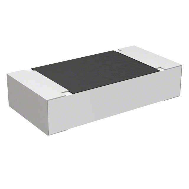
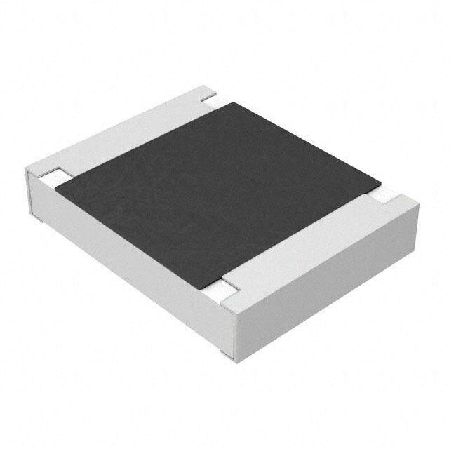
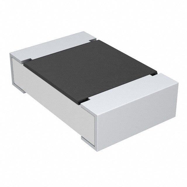
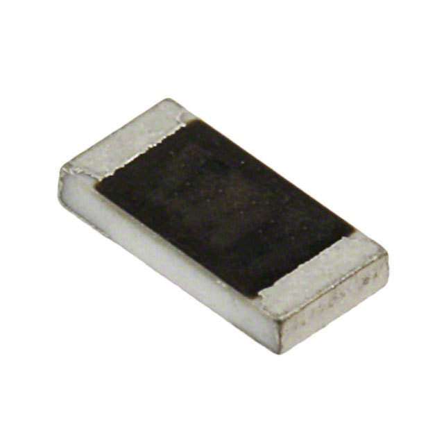
ICGOO电子元器件商城为您提供ERJ-1GEF2702C由Panasonic Corporation设计生产,在icgoo商城现货销售,并且可以通过原厂、代理商等渠道进行代购。 ERJ-1GEF2702C价格参考¥0.13-¥0.13。Panasonic CorporationERJ-1GEF2702C封装/规格:芯片电阻 - 表面安装, 27 kOhms ±1% 0.05W,1/20W 厚膜 芯片电阻 0201(0603 公制) 厚膜。您可以下载ERJ-1GEF2702C参考资料、Datasheet数据手册功能说明书,资料中有ERJ-1GEF2702C 详细功能的应用电路图电压和使用方法及教程。
| 参数 | 数值 |
| 产品目录 | |
| 描述 | RES 27K OHM 1/20W 1% 0201 SMD厚膜电阻器 - SMD 0201 27Kohms 1% Tolerance |
| 产品分类 | |
| 品牌 | Panasonic Electronic Components |
| 产品手册 | |
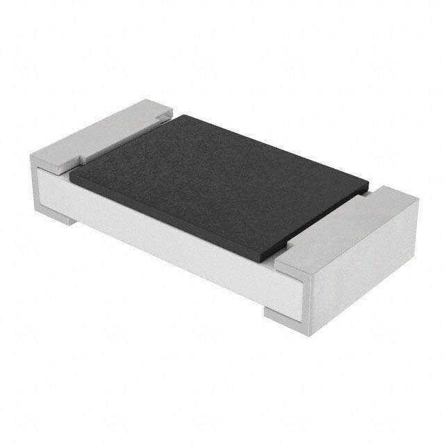
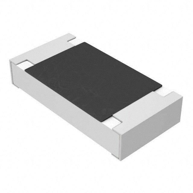
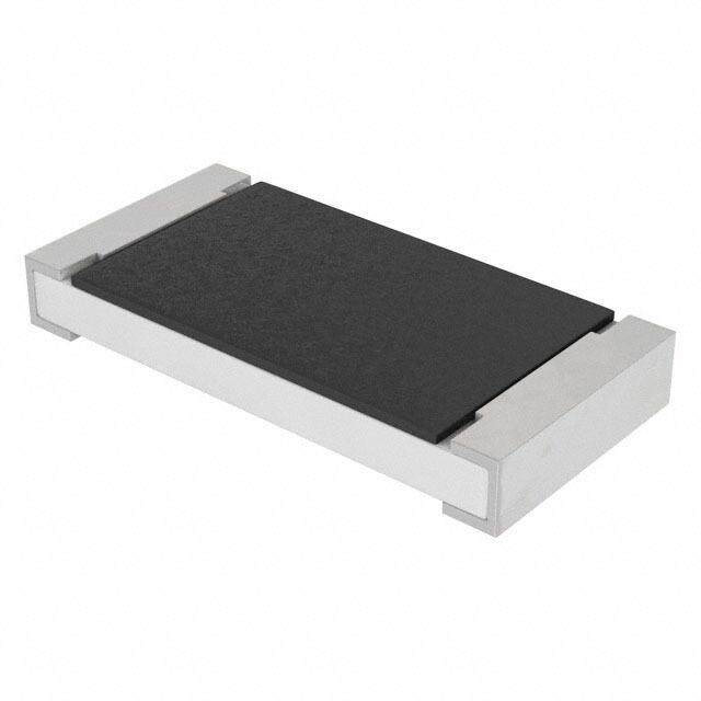
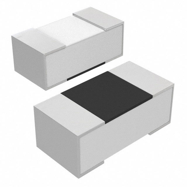
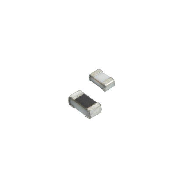
| 产品图片 |
|
| rohs | RoHS 合规性豁免无铅 / 符合限制有害物质指令(RoHS)规范要求 |
| 产品系列 | 薄膜电阻器,厚膜电阻器 - SMD,Panasonic ERJ-1GEF2702CERJ |
| 数据手册 | |
| 产品型号 | ERJ-1GEF2702C |
| 产品 | Thick Film Resistors SMD |
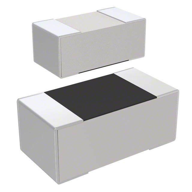
| 产品目录绘图 |
|
| 产品目录页面 | |
| 产品种类 | 厚膜电阻器 - SMD |
| 供应商器件封装 | 0201 |
| 其它名称 | ERJ-1GEF273C |
| 功率(W) | 0.05W,1/20W |
| 功率额定值 | 50 mW |
| 包装 | 带卷 (TR) |
| 商标 | Panasonic |
| 外壳代码-in | 0201 |
| 外壳代码-mm | 0603 |
| 外壳宽度 | 0.3 mm |
| 外壳长度 | 0.6 mm |
| 外壳高度 | 0.23 mm |
| 大小/尺寸 | 0.024" 长 x 0.012" 宽(0.60mm x 0.30mm) |
| 容差 | ±1% |
| 封装 | Reel |
| 封装/外壳 | 0201(0603 公制) |
| 封装/箱体 | 0201 (0603 metric) |
| 工作温度范围 | - 55 C to + 125 C |
| 工厂包装数量 | 15000 |
| 成分 | 厚膜 |
| 标准包装 | 15,000 |
| 温度系数 | ±200ppm/°C |
| 特性 | - |
| 电压额定值 | 25 V |
| 电阻 | 27 kOhms |
| 电阻(Ω) | 27k |
| 端子数 | 2 |
| 类型 | Precision Thick Film Chip Resistors |
| 系列 | ERJ |
| 高度 | 0.010"(0.26mm) |




- 商务部:美国ITC正式对集成电路等产品启动337调查
- 曝三星4nm工艺存在良率问题 高通将骁龙8 Gen1或转产台积电
- 太阳诱电将投资9.5亿元在常州建新厂生产MLCC 预计2023年完工
- 英特尔发布欧洲新工厂建设计划 深化IDM 2.0 战略
- 台积电先进制程称霸业界 有大客户加持明年业绩稳了
- 达到5530亿美元!SIA预计今年全球半导体销售额将创下新高
- 英特尔拟将自动驾驶子公司Mobileye上市 估值或超500亿美元
- 三星加码芯片和SET,合并消费电子和移动部门,撤换高东真等 CEO
- 三星电子宣布重大人事变动 还合并消费电子和移动部门
- 海关总署:前11个月进口集成电路产品价值2.52万亿元 增长14.8%


PDF Datasheet 数据手册内容提取
Precision Thick Film Chip Resistors Precision Thick Film Chip Resistors Type: ERJ XG, 1G ERJ 1R, 2R, 3R, 6R ERJ 3E, 6E, 8E, 14, 12, 1T Features ● Small size and lightweight ● High reliability Metal glaze thick fi lm resistive element and three layers of electrodes ● Compatible with placement machines Taping packaging available ● Suitable for both refl ow and fl ow soldering ● Low Resistance Tolerance ERJXG, 1G, 2R, 3E, 6E, 8E, 14, 12, 1T Type : ±1 % ERJ1R, 2R, 3R, 6R Type : ±0.5 % ● Reference Standards IEC 60115-8, JIS C 5201-8, EIAJ RC-2134B ● AEC-Q200 qualifi ed (Exemption ERJXG, ERJ1R) ● RoHS compliant ■ As for Packaging Methods, Land Pattern, Soldering Conditions and Safety Precautions, Please see Data Files Explanation of Part Numbers ● ERJ1R, 2R, 3R, 6R Type, ±0.5 % 1 2 3 4 5 6 7 8 9 10 11 12 E R J 3 R B D 1 0 0 2 V Product Code Size, Power Rating T.C.R. Marking Resistance Tolerance Packaging Methods Thick Film Code Inch Power R. Code T.C.R. Code Tolerance Code Packaging Part No. Chip Resistors 1R 0201 0.05 W H ±50×10–6/˚C (1R, 2R) D ±0.5 % Pressed Carrier Taping 2R 0402 0.063 W B ±50×10–6/˚C (3R, 6R) C 2 mm pitch, 15,000 pcs. ERJ1R 3R 0603 0.1 W K ±100×10–6/˚C (2R) Punched Carrier Taping 6R 0805 0.1 W E ±100×10–6/˚C (3R, 6R) X 2 mm pitch, 10,000 pcs. ERJ2R Punched Carrier Taping ERJ3R V 4 mm pitch, 5,000 pcs. ERJ6R Resistance Value The first three digits are significant figures of resistance and the last one denotes number of zeros following. Example: 1002 →10 kΩ Design and specifications are each subject to change without notice. Ask factory for the current technical specifications before purchase and/or use. Should a safety concern arise regarding this product, please be sure to contact us immediately. 05 Sep. 2014
Precision Thick Film Chip Resistors ● ERJXG, 1G, 2R, 3E, 6E, 8E, 14, 12, 1T Type, ±1 % 1 2 3 4 5 6 7 8 9 10 11 12 E R J 8 E N F 1 0 0 2 V Product Code Size, Power Rating Resistance Tolerance Packaging Methods Thick Film Code Inch Power R. Code Tolerance Code Packaging Part No. Chip Resistors XGN 01005 0.031 W F ±1 % Pressed Carrier Taping 1GN 0201 0.05 W Y 2 mm pitch, 20,000 pcs. ERJXGN 2RK 0402 0.1 W Pressed Carrier Taping 3EK 0603 0.1 W C 2 mm pitch, 15,000 pcs. ERJ1GN 6EN 0805 0.125 W Resistance Value Punched Carrier Taping X ERJ2RK 8EN 1206 0.25 W The first three digits are significant figures 2 mm pitch, 10,000 pcs. 14N 1210 0.5 W of resistance and the last one denotes ERJ3EK Punched Carrier Taping 12N 1812 0.75 W number of zeros following. V 4 mm pitch, 5,000 pcs. ERJ6EN Decimal point is expressed by "R". ERJ8EN 12S 2010 0.75 W 1TN 2512 1 W Example : 1002 → 10 kΩ Embossed Carrier Taping ERJ14N ERJ12N 4 mm pitch, 5,000 pcs. U ERJ12S Embossed Carrier Taping ERJ1TN 4 mm pitch, 4,000 pcs. Construction Dimensions in mm (not to scale) L a W Protective coating t Alumina substrate b Electrode (Inner) Part No. Dimensions (mm) Mass (Weight) (inch size) L W a b t [g/1000 pcs.] ERJXG (01005) 0.40±0.02 0.20±0.02 0.10±0.03 0.10±0.03 0.13±0.02 0.04 ERJ1G, 1R (0201) 0.60±0.03 0.30±0.03 0.10±0.05 0.15±0.05 0.23±0.03 0.15 Electrode (Between) E(0R4J022R)□ 1.00±0.05 0.50±0.05 0.20±0.10 0.25±0.05 0.35±0.05 0.8 ERJ3R□ E(0R6J033E)K 1.60±0.15 0.80+–00..0155 0.30±0.20 0.30±0.15 0.45±0.10 2 ERJ6R□ ERJ6EN 2.00±0.20 1.25±0.10 0.40±0.20 0.40±0.20 0.60±0.10 4 Thick film (0805) resistive element Electrode (Outer) ERJ8EN (1206) 3.20+–00..2005 1.60+–00..1055 0.50±0.20 0.50±0.20 0.60±0.10 10 ERJ14N (1210) 3.20±0.20 2.50±0.20 0.50±0.20 0.50±0.20 0.60±0.10 16 ERJ12N (1812) 4.50±0.20 3.20±0.20 0.50±0.20 0.50±0.20 0.60±0.10 27 ERJ12S (2010) 5.00±0.20 2.50±0.20 0.60±0.20 0.60±0.20 0.60±0.10 27 ERJ1TN (2512) 6.40±0.20 3.20±0.20 0.65±0.20 0.60±0.20 0.60±0.10 45 Design and specifications are each subject to change without notice. Ask factory for the current technical specifications before purchase and/or use. Should a safety concern arise regarding this product, please be sure to contact us immediately. 05 Sep. 2014
Precision Thick Film Chip Resistors Ratings <±0.5 %> Power Rating Limiting Element Maximum Overload Resistance Resistance Category (iPnacrht sNizoe.) at (7W0 )°C Vol t(aVg)e(1) Volt(aVg)e(2) Tole(%ra)nce Ra(Ωng)e (×T1.C0–.6R/°.C) Tempera(°tuCre) Range ERJ1RH 1 k to 1 M (0201) 0.05 15 30 ±0.5 (E24, E96) ±50 –55 to +125 ERJ2RH 100 to 100 k (0402) 0.063 50 100 ±0.5 (E24, E96) ±50 –55 to +125 ERJ2RK 10 to 97.6 (0402) 0.063 50 100 ±0.5 102 k to 1 M ±100 –55 to +125 (E24, E96) ERJ3RB 100 to 100 k (0603) 0.1 50 100 ±0.5 (E24, E96) ±50 –55 to +125 ERJ3RE 10 to 97.6 (0603) 0.1 50 100 ±0.5 102 k to 1 M ±100 –55 to +125 (E24, E96) ERJ6RB 100 to 100 k (0805) 0.1 150 200 ±0.5 (E24, E96) ±50 –55 to +125 ERJ6RE 10 to 97.6 (0805) 0.1 150 200 ±0.5 102 k to 1 M ±100 –55 to +125 (E24, E96) <±1 %> Power Rating Limiting Element Maximum Overload Resistance Resistance Category (iPnacrht sNizoe.) at (7W0 )°C Vol t(aVg)e(1) Volt(aVg)e(2) Tole(%ra)nce Ra(Ωng)e (×T1.C0–.6R/°.C) Tempera(°tuCre) Range ERJXGN 10 to 1 M <100 Ω : ±300 (01005) 0.031 15 30 ±1 (E24, E96) 100 Ω < : ±200 –55 to +125 ERJ1GN 10 to 1 M(3) (0201) 0.05 25 50 ±1 (E24, E96) ±200 –55 to +125 ERJ2RK 10 to 1 M(3) (0402) 0.1 50 100 ±1 (E24, E96) ±100 –55 to +155 ERJ3EK 10 to 1 M (0603) 0.1 75 150 ±1 (E24, E96) ±100 –55 to +155 ERJ6EN 10 to 2.2 M (0805) 0.125 150 200 ±1 (E24, E96) ±100 –55 to +155 ERJ8EN 10 to 2.2 M (1206) 0.25 200 400 ±1 (E24, E96) ±100 –55 to +155 ERJ14N 10 to 1 M (1210) 0.5 200 400 ±1 (E24, E96) ±100 –55 to +155 ERJ12N 10 to 1 M (1812) 0.75 200 500 ±1 (E24, E96) ±100 –55 to +155 ERJ12S 10 to 1 M (2010) 0.75 200 500 ±1 (E24, E96) ±100 –55 to +155 ERJ1TN 10 to 1 M (2512) 1 200 500 ±1 (E24, E96) ±100 –55 to +155 (1) Rated Continuous Working Voltage (RCWV) shall be det erm ined from RCWV=√Power Rating × Res is tance Values, or Limiting Element Voltage list ed above, whichever less. (2) Overload (Short-time Overload) Test Voltage (SOTV) shall be det ermined from SOTV=2.5 (Only ERJ2RK ±1% =2.0) × Power Rating or max. Over load Volt age list ed above whichever less. (3) Please contact us when you need a type with a resistance of less than 10 Ω. Power Derating Curve –55 °C 70 °C For resistors operated in ambient temperatures above 100 70 °C, power rating shall be derated in accordance %) 80 with the figure on the right. d ( 60 2RK, 3E, 6E, 8E, a 14, 12, 1T o L ed 40 XG, 1G, 1R, 2RH, Rat 20 2RK, 3R, 6R 155 °C 125 °C 0 –60 –40 –20 0 20 40 60 80 100 120 140 160 180 Ambient Temperature (°C) Design and specifications are each subject to change without notice. Ask factory for the current technical specifications before purchase and/or use. Should a safety concern arise regarding this product, please be sure to contact us immediately. 05 Sep. 2014

 Datasheet下载

