ICGOO在线商城 > EN2P3M20PK
- 型号: EN2P3M20PK
- 制造商: Switchcraft
- 库位|库存: xxxx|xxxx
- 要求:
| 数量阶梯 | 香港交货 | 国内含税 |
| +xxxx | $xxxx | ¥xxxx |
查看当月历史价格
查看今年历史价格
EN2P3M20PK产品简介:
ICGOO电子元器件商城为您提供EN2P3M20PK由Switchcraft设计生产,在icgoo商城现货销售,并且可以通过原厂、代理商等渠道进行代购。 提供EN2P3M20PK价格参考¥26.62-¥33.77以及SwitchcraftEN2P3M20PK封装/规格参数等产品信息。 你可以下载EN2P3M20PK参考资料、Datasheet数据手册功能说明书, 资料中有EN2P3M20PK详细功能的应用电路图电压和使用方法及教程。
| 参数 | 数值 |
| 产品目录 | |
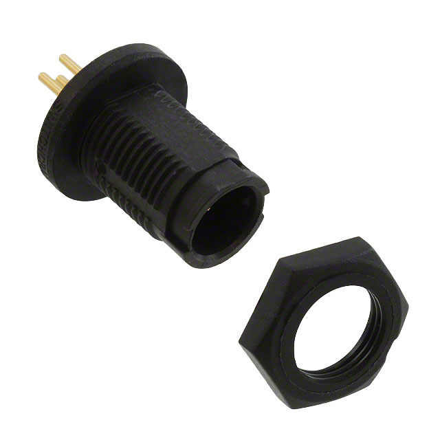
| 描述 | CONN RCPT 3POS PANEL MOUNT PIN |
| 产品分类 | |
| 品牌 | Switchcraft Inc. |
| 数据手册 | |
| 产品图片 |
|
| 产品型号 | EN2P3M20PK |
| rohs | 无铅 / 符合限制有害物质指令(RoHS)规范要求 |
| 产品系列 | EN2™ |
| 侵入防护 | IP68 - 防尘,防水 |
| 其它名称 | SC1615 |
| 包装 | 散装 |
| 外壳尺寸-插件 | - |
| 外壳尺寸,MIL | - |
| 外壳材料,镀层 | 热塑塑胶 |
| 安装类型 | 面板安装,隔墙式(前端螺母) |
| 工作温度 | -40°C ~ 85°C |
| 朝向 | 带标记 |
| 标准包装 | 1 |
| 特性 | 组件套件 |
| 特色产品 | http://www.digikey.cn/product-highlights/cn/zh/switchcraft-en2-sealed-cord-connector/3717 |
| 电压-额定 | 125VAC/DC |
| 相关产品 | /product-detail/zh/EN2CAPIP/EN2CAPIP-ND/5013306/product-detail/zh/16295/SC1398-ND/2523443 |
| 端接 | |
| 紧固类型 | 插销锁 |
| 触头镀层 | 金 |
| 触头镀层厚度 | - |
| 连接器类型 | 插座,公形引脚 |
| 配套产品 | /product-detail/zh/EN2C3F20G1/SC1674-ND/3880494/product-detail/zh/EN2C3F20G2/SC1673-ND/3880493/product-detail/zh/EN2C3F20G3/SC1672-ND/3880492/product-detail/zh/EN2C3F20DCW/SC1665-ND/3880468/product-detail/zh/EN2C3F20DC/SC1671-ND/3880412/product-detail/zh/EN2C3F20G1W/SC1668-ND/3880403/product-detail/zh/EN2C3F20G2W/SC1667-ND/3880402/product-detail/zh/EN2C3F20G3W/SC1666-ND/3880401 |
| 针脚数 | 3 |
| 额定电流 | - |



- 商务部:美国ITC正式对集成电路等产品启动337调查
- 曝三星4nm工艺存在良率问题 高通将骁龙8 Gen1或转产台积电
- 太阳诱电将投资9.5亿元在常州建新厂生产MLCC 预计2023年完工
- 英特尔发布欧洲新工厂建设计划 深化IDM 2.0 战略
- 台积电先进制程称霸业界 有大客户加持明年业绩稳了
- 达到5530亿美元!SIA预计今年全球半导体销售额将创下新高
- 英特尔拟将自动驾驶子公司Mobileye上市 估值或超500亿美元
- 三星加码芯片和SET,合并消费电子和移动部门,撤换高东真等 CEO
- 三星电子宣布重大人事变动 还合并消费电子和移动部门
- 海关总署:前11个月进口集成电路产品价值2.52万亿元 增长14.8%


PDF Datasheet 数据手册内容提取
8 7 6 5 4 3 2 1 2 2 3 3 4 3 4 3 4 SPECIFICATIONS: MECHANICAL 1 2 2 5 2 5 2 5 Life:600 cycles minimum Vibration: Mil-Std 202G Method 201A Hex Nut Tongue: 5-6 in-lb F F 1 3 1 4 1 1 6 1 6 ELECTRICAL 7 Voltage Rating: 250 V AC/DC for 2 contact arrangement 2-#20 3-#20 4-#22 5-#26 6-#26 7-#26 125 V AC/DC for 3-7 contact arrangements CONTACT ARRANGEMENTS Insulation Resistance: 1000 mΩ minimum PANEL CONNECTOR REAR (WIRING SIDE) VIEW Contact Resistance: 10 mΩ maximum Current Rating: Refer to Current Rating Table PART NUMBER SCHEME: ENVIRONMENTAL EN2 PANEL CONNECTOR FIELD ASSEMBLY INSTRUCTIONS: Operating Temperature Limits:-40ºC to +85ºC (-40ºF to +185°F), EN2 see Current Rating Table. Moisture Resistance: Mil-Std 202G Method 106G Strip cable end and conductors as shown. 0.375 MIN. Insulation Resistance: Mil-Std 202G Method 302 9.53 Connector Type: Packaging Options: Thermal Shock: Mil-Std 202G Method 107G C - Cord Leave blank for Bulk Salt Atmosphere (Corrosion): Mil-Std 202G Method 101E P - Panel* K - Kit (one unit/bag) Wearthetight Ratings: E L - In-Line** IP16, IP18, IP66, IP67, IP68 per IEC60529 E 0.188±0.015 NEMA 250 (6P), CFR 46 Part 110.20 EN2 PANEL-MOUNT 4.78±0.38 # of Contacts: Coupling Ring option: CONNECTOR 2-3 for #20 Leave blank for Ribbed MATERIAL 4 for #22 W - Winged CABLE 5-7 for #26 Connector Housing ----- Thermoplastic, black Hex Nut: ------------------- Thermoplastic, black Gender: Grommet Code - Cable O.D. Range: Coupling Ring ------------ Thermoplastic, black M - Male DC - Daisy Chain (all 3 sizes) Cable Clamp -------------- Thermoplastic, black F - Female G1 - 0.100-0.140 (2.5-3.6) Handle (back-shell) ----- Thermoplastic, black G2 - 0.140-0.180 (3.6-4.6) Insulator ------------------- Elastomer, black G3 - 0.180-0.220 (4.6-5.6) Seal Grommet ----------- Elastomer, black Contacts ------------------- Copper Alloy, plated Contact Size: Contact Style: SOLDER OR CRIMP CONTACTS 20 - #20 Leave blank for Solder or Crimp 2226 -- ##2262 P - PC tail (Panel connectors only) Contacts (Wawirge) at OpeCrautrirnegn tT Rematpinegr a(tAu)r e ( ° C ) D Soldering or crimping conductors to contacts is recommended before insertion into connector. * for mating Cord connectors refer to EN2C SERIES drawing. 20 45°C7 max.55°C6 max.65°C5 max.75°C4 max.85°C3. 5max. D If crimping, use hand or pneumatic crimp tool with crimp positioner per contact size. ** Mating In-Line connectors not currently available. 22 5.5 5 4 3 2.5 If soldering after contacts are inserted in the connector, limit exposure of contacts 2 #20 24 5.5 5 4 3 2.5 to soldering iron temperature to 4 sec. maximum. Soldering iron temperature should 26 4 3.5 2.5 2 1 not exceed 650°F (343°C). 20 6.5 5.5 4.5 3.5 2 22 5 4.5 3.5 3 1.5 3 #20 24 5 4.5 3.5 3 1.5 0.250 MAX PANEL THICKNESS 26 3 2.5 2 1.5 0.5 6.35 20 5 4.5 3.5 3 1.5 22 4.5 4 3 2 1 4 #22 24 4.5 4 3 2 1 26 3 2.5 2 1.5 0.5 26 3 2.5 2 1.5 1 5-7 #26 28 2.5 2 1.5 1 0.5 30 2 1.5 1 0.5 0.5 C C PIN CONTACTS SOCKET CONTACTS Insert wired contacts into connector housing using an insertion tool and per contacts arrangements. (MALE) (FEMALE) Align and install connector into panel cut-out. Tighten hex nut 5 -6 in-lb. 0.790 20.07 0.620 0.401 0.625 0.588 15.75 10.19 0.20 [5.1] TYP 0.200 [5.1] TYP 15.88 14.94 0.15 [3.8] FOR 5-7 #26 CONTACTS 0.15 [3.8] FOR 5-7 #26 CONTACTS 0.716 0.430 B 18.18 10.92 B 0.202 [5.1] BEFORE PANEL MOUNTING, REDUCED BY 0.010 [0.25] AFTER MOUNTING 0.107 0.140 RECOMMENDED SOLDER OR CRIMP TYPE CONTACTS PC TAIL TYPE CONTACTS 2.72 3.56 PANEL CUT-OUT PIN 1 INDICATOR ±0.003 [±0.08] ALL DIMENSIONS FOR REFERENCE ONLY CUSTOMER DRAWING TOOL TOOL TYPE POSITIONER CONTACT SIZE WIRE SIZES THIS DRAWING DESCRIBES A DESIGN CONSIDERED PROPRIETARY IN NATURE, DEVELOPED AND MANUFACTURED BY SWITCHCRAFT INC. AND IS RELEASED ON A CONFIDENTIAL BASIS FOR IDENTIFICATION PURPOSES ONLY. EN3CR HAND CRIMP TOOL EN2POS20 20 and 22 20 and 22 AWG UNLESS OTHERWISE SPECIFIED SIZE WIDTH MULT LBS/M TEMPER EN3POS26 26 26, 28, and 30 AWG A EN2POS20 20 and 22 20 and 22 AWG 1. ALL DIMENSIONS IN INCHES FINISH MATERIAL A EN3CRAUTO PNEUMATIC CRIMP TOOL EN3POS26 26 26, 28, and 30 AWG 0D SPECS UPDATED 10/03/13 PNK SRC - TWO PLACE DECIMALS 0.02 SPEC No. SPEC No. FIRST USED ON SCALE EN2CRL HAND CRIMP TOOL 0C SPECS UPDATED 09/20/12 PNK SRC - THREE PLACE DECIMALS 0.005 1.5:1 LARGE FRAME EN2POS20L 20 and 22 20, 22, 24, and 26 AWG 0B TOOLS REVISED 05/14/12 PNK * DATE DRAWN BY CHKD APVD EN2CRAUTOL PNEULMAARTGICE CFRRIAMMPE TOOL 0A PRELIMINARY 02/09/12 PNK * 02/09/12 PNK 02P/0N9K/12 02S/0R9C/12 SHEET 1 OF 2 EN3INS20 CONTACT -- 20 and 22 -- REV ECO NUMBER DATE BY APVD NAME PART No. REV EN3INS26 INSERTION/EXTRUCTION -- 26 -- REVISIONS DO NOT SCALE DRAWING EN2P SERIES CONNECTORS, RoHS EN2P SERIES 0D 8 7 6 5 4 SolidWorks CAD File C
8 7 6 5 4 3 2 1 0.114 0.099 2.90 2.51 0.049 0.057 0.200 1.25 1.45 5.08 2 TYP F 0.057 F 1 1.45 0.029 0.040 0.72 1.02 2 TYP 3 1 2 and 3-#20 E 2-#20 3-#20 E PIN ARRANGEMENTS (0.046 [1.17] RECOMMENDED PCB HOLE SIZE) 0.100 0.200 2.54 0.050 5.08 1.27 TYP 3 2 D D 0.100 2.54 0.040 0.050 1.02 4 1 1.27 TYP 4-#22 4-#22 PIN ARRANGEMENT (0.046 [1.17] RECOMMENDED PCB HOLE SIZE) C 30° TYP 30° TYP 30° TYP C 4 3 4 3 4 3 0.150 3.81 0.164 0.164 0.164 TYP 4.17 4.17 4.17 5 2 5 2 5 2 B 0.020 B 1 6 1 6 1 0.51 TYP 7 5, 6, and 7-#26 5-#26 6-#26 7-#26 PIN ARRANGEMENTS (0.026 [0.66] RECOMMENDED PCB HOLE SIZE) CUSTOMER DRAWING THIS DRAWING DESCRIBES A DESIGN CONSIDERED PROPRIETARY IN NATURE, DEVELOPED AND MANUFACTURED CONTACT ARRANGEMENTS BY SWITCHCRAFT INC. AND IS RELEASED ON A CONFIDENTIAL BASIS FOR IDENTIFICATION PURPOSES ONLY. UNLESS OTHERWISE SPECIFIED SIZE WIDTH MULT LBS/M TEMPER PANEL CONNECTOR FRONT VIEW (PCB COMPONENT SIDE) A 1. ALL DIMENSIONS IN INCHES FINISH MATERIAL A (RECOMMENDED PCB HOLE LAYOUT WITHIN ±0.001 [0.025]) - TWO PLACE DECIMALS 0.02 SPEC No. SPEC No. FIRST USED ON SCALE - THREE PLACE DECIMALS 0.005 1.5:1 DATE DRAWN BY CHKD APVD PNK SRC OD SPECS UPDATED 10/03/13 PNK SRC 02/09/12 PNK 02/09/12 02/09/12 SHEET 2 OF 2 REV ECO NUMBER DATE BY APVD NAME PART No. REV REVISIONS DO NOT SCALE DRAWING EN2P SERIES CONNECTORS, RoHS EN2P SERIES 0D 8 7 6 5 4 SolidWorks CAD File C
 Datasheet下载

