ICGOO在线商城 > ELUMEESAQ6C22

 Datasheet下载
- 型号: ELUMEESAQ6C22
- 制造商: C&K Components
- 库位|库存: xxxx|xxxx
- 要求:
| 数量阶梯 | 香港交货 | 国内含税 |
| +xxxx | $xxxx | ¥xxxx |
查看当月历史价格
查看今年历史价格
ELUMEESAQ6C22产品简介:
ICGOO电子元器件商城为您提供ELUMEESAQ6C22由C&K Components设计生产,在icgoo商城现货销售,并且可以通过原厂、代理商等渠道进行代购。 提供ELUMEESAQ6C22价格参考以及C&K ComponentsELUMEESAQ6C22封装/规格参数等产品信息。 你可以下载ELUMEESAQ6C22参考资料、Datasheet数据手册功能说明书, 资料中有ELUMEESAQ6C22详细功能的应用电路图电压和使用方法及教程。
| 参数 | 数值 |
| 3D型号 | http://media.digikey.com/pdf/3D%20Models/C&K/elumeesaxxc22_082511.zip点击此处下载产品Datasheet |
| 产品目录 | |
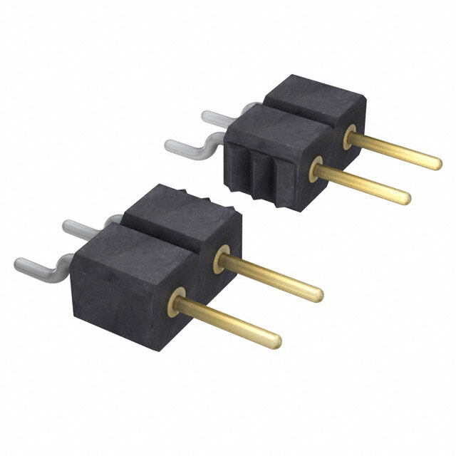
| 描述 | SWITCH PUSH SPDT 0.25A 50V发光按钮开关 PUSHBUTTON SWITCH |
| 产品分类 | |
| 品牌 | C&K Components |
| 产品手册 | |
| 产品图片 |
|
| rohs | 符合RoHS无铅 / 符合限制有害物质指令(RoHS)规范要求 |
| 产品系列 | 发光开关,发光按钮开关,C&K Components ELUMEESAQ6C22ELUM™ |
| mouser_ship_limit | 该产品可能需要其他文件才能进口到中国。 |
| 数据手册 | http://www.ck-components.com/index.php?module=media&action=Display&cmpref=13340&lang=en&width=&height=&format=&alt= |
| 产品型号 | ELUMEESAQ6C22 |
| PCN组件/产地 | |
| 产品培训模块 | http://www.digikey.cn/PTM/IndividualPTM.page?site=cn&lang=zhs&ptm=30201http://www.digikey.cn/PTM/IndividualPTM.page?site=cn&lang=zhs&ptm=30457 |
| 产品目录绘图 |
|
| 产品目录页面 | |
| 产品种类 | Pushbutton Switches |
| 侵入防护 | - |
| 其它名称 | CKN10208TR |
| 功率额定值 | 3.5 VA |
| 包装 | 带卷 (TR) |
| 可燃性等级 | UL 94 V-0 |
| 商标 | C&K Components |
| 安装类型 | 表面贴装,直角 |
| 安装风格 | SMD/SMT |
| 工作温度 | -40°C ~ 80°C |
| 工厂包装数量 | 450 |
| 开关功能 | ON - OFF |
| 执行器 | Without Cap |
| 机械寿命 | - |
| 标准包装 | 450 |
| 照明 | LED |
| 照明电压(标称值) | 2 VDC |
| 照明类型,颜色 | LED,绿 |
| 照明颜色 | Green |
| 特性 | - |
| 特点 | Button/cap ordered separately |
| 电压额定值DC | 50 V |
| 电气寿命 | - |
| 电流额定值 | 250 mA |
| 电路 | SPDT |
| 相关产品 | /product-detail/zh/181D01000/CKN9456-ND/1949276/product-detail/zh/181D00000/CKN9455-ND/1949275 |
| 端子类型 | 鸥翼型 |
| 类型 | 标准,发光式 |
| 系列 | ELUM |
| 致动器类型 | 帽盖 |
| 触点形式 | SPDT |
| 触点电镀 | Silver |
| 面板开口尺寸 | - |
| 颜色-致动器/盖帽 | 黑 |
| 额定电压-AC | - |
| 额定电压-DC | 50V |
| 额定电流 | 250mA(DC) |


- 商务部:美国ITC正式对集成电路等产品启动337调查
- 曝三星4nm工艺存在良率问题 高通将骁龙8 Gen1或转产台积电
- 太阳诱电将投资9.5亿元在常州建新厂生产MLCC 预计2023年完工
- 英特尔发布欧洲新工厂建设计划 深化IDM 2.0 战略
- 台积电先进制程称霸业界 有大客户加持明年业绩稳了
- 达到5530亿美元!SIA预计今年全球半导体销售额将创下新高
- 英特尔拟将自动驾驶子公司Mobileye上市 估值或超500亿美元
- 三星加码芯片和SET,合并消费电子和移动部门,撤换高东真等 CEO
- 三星电子宣布重大人事变动 还合并消费电子和移动部门
- 海关总署:前11个月进口集成电路产品价值2.52万亿元 增长14.8%

.jpg)

PDF Datasheet 数据手册内容提取
ELUMTM Series LEAD FREE Right Angle Illuminated Latching Pushbutton COMPATIBLE OPTION Features/Benefits Typical Applications Patent Numbers A • SPDT (N.O. & N.C.) • Telecom network equipment 6,974,924 B2 US EP1583118B1 Europe • Low height above PCB • Automotive electronics n o • Reliable self-cleaning contact • Consumer electronics t ut • Surface-mount or thru-hole PCB • Computer, server, modem, b • Standard or custom actuator data storage h s • Central LED illumination • Professional instrumentation, u medical P • Latching or Momentary • Long travel. Smooth feel • RoHS compliant and compatible Materials Operating Environment FIXED C ONTACTS: Stainless steel, silver plated with gold flash OPERATING TEMPERATURE: -40˚C TO 80˚C. TERMINALS: Stainless steel, silver plated STORAGE TEMPERATURE: -40˚C TO 80˚C. MOVABL E CONTACTS: Copper alloy, silver plated with RELATIVE HUMIDITY: 90% R.H. @ 80˚C. gold flash OPERATING LIFE: 30,000 Cycles. BASE: Glass filled LCP (UL94V-0) VIBRATION: Per EIA 186-E Method ACTUATOR: Glass filled nylon 4/6 (UL94V-0) MECHANICAL SHOCK: Per EIA 186-E Method 12. COVER: Stainless steel OVERLOAD: Withstands 40 N for 1 minute without damage Electrical Process Environment MAXIMUM POWER: 3.5 VA SOLDERABILITY: According to Mil STD 202F Method 208D or EIA MIN./MAX. VOLTAGE: 20 mV – 50 VDC RS-186E Method 9. MIN./MAX. CURRENT: 0.01 mA – 250 mA LEAD FREE PROCESS COMPATIBLE: 260˚C peak, 10 seconds Max. DIELECTRIC STRENGTH: ≥ 250 Vrms above 250º C. CONTACT RESISTANCE: ≤ 50 mΩ WASHING PROCESS: No clean process compatible (SMT) INSULATION RESISTANCE: ≥ 109 Ω Bottom wash compatible (Thru-hole) BOUNCE TIME: ≤1 ms SHEAR TEST (SWITCH/PCB): > 40 N LED SPECIFICATIONS: See page A-5 Packaging Mechanical “SA” Terminal Style SMT: Tape and reel per EIA 481-2 (450/reel) OPERATING FORCE: 2.5 N at Full Travel “TH” Terminal Style PC: Tray (60/tray) SWITCHING TRAVEL: .067” (1.7 mm) NOTE: Any models supplied with Q, contact material are RoHS compliant. LATCH TRAVEL: .131” (3.6 mm) FULL TRAVEL: .200” (5.1 mm) NOTE: Specifications and materials listed above are for switches with standard options. For information on specific and custom switches, please contact Customer Service. Build-A-Switch To order, simply select desired option from each category and place in the appropriate box. E L U M Q Designation ELUM ELUM Series Switch Function OA Momentary OC*** Momentary short travel Actuator Style** EE Latching (push-push) C02 Black without window Terminal Style C12 Black with window TH Right Angle, PC thru-hole C22 Black with window and snap SA Right Angle, surface mount feature for custom actuators Contact Material* Q Silver with gold flash Illumination (NONE) Models without illumination 1 LED White 2 LED Bi-color – Red (Green) 3 LED Red 5 LED Amber * Other plating options available, please contact Customer Service. ** Custom actuators available, please contact Customer Service. 6 LED Green *** Short travel available in momentary only. 7 LED Blue Third Angle 8 LED Bi-Color – Amber (Green) Projection Dimensions are shown: Inches (mm) Specifications and dimensions subject to change www.ckswitches.com A-4
ELUMTM Series Right Angle Illuminated Latching Pushbutton STANDARD OPTIONS A ELUMEESAQ7C12 ELUMOATHQ6C12 P .100 TYP. u .197 (2,53) (.10,4002 )TYP. .197 (.21,0503 )TYP. (.10,4002 )TYP. sh (5,01) (5,01) b u SURFACE MOUNT .450 PC THRU-HOLE .450 t (11,43) (11,43) t o .292 (7.2,4922) n (7,42) .070 TYP. .300 (1,78) (7,62) .300 (7,62) .810 .(029,451 Dø)IA. (3.1,0240) (2.08,1508) (2.,04915ø )DIA. (2.,19125) (20,58) (5.,21063) .157 .237 .157 (3,99) .824 (6,01) (3,99) .005 (20,94) .033 TYP. (0,12) PCB SURFACE (0,84) .854 PCB SURFACE (21,7) .068 TYP. (1,73) ACTUATOR SHOWN EXTENDED POSITION ACTUATOR SHOWN EXTENDED POSITION ELUMEESAQ3C22 .450 (11,43) .200 (5,08) SURFACE MOUNT .810 .131 DIA. .160 (20,58) (3.33ø) (4,06) .237 .824 (6,01) (20,94) .854 (21,7) ACTUATOR SHOWN EXTENDED POSITION DESIGNATION E L U M ELUM ELUM SERIES, Illuminated Latching Pushbutton SWITCH FUNCTION POSITION 1 POSITION 2 SCHEMATIC SWITCH CONNECTED SWITCH CONNECTED 3C OPTION CODE NO. OF POLES FUNCTION TERMINALS FUNCTION TERMINALS 4 NC NO 2 OA / OC MomSePntary ON 3 – 4 ON (Mom.) 3 – 2 SPDT 5 1 EE Latching S(PPush-Push) ON 3 – 4 ON 3 – 2 + Anode – Cathode For SPST N.O. function, only terminals 3 & 2 are used. LED pins 1 & 5 are independent of For SPST N.C. function, only terminals 3 & 4 are used. switch function. Circuit: Make before break NOTE: + Anode - Cathode For bi-color LED’s the polarity must be reversed to alternate the color 5 1 Third Angle Projection Dimensions are shown: Inches (mm) Specifications and dimensions subject to change www.ckswitches.com A-5 fix-mjc
ELUMTM Series Right Angle Illuminated Latching Pushbutton TERMINAL STYLE A SA TH n RIGHT ANGLE, SURFACE MOUNT RIGHT ANGLE, PC THRU-HOLE o REF. SURFACE t REF. SURFACE t hbu (10.4,8268) 4 3 .1(47,44 2T)YP. (1.0,5672ø D)IA. TYP. .348 .174 TYP. s 2 (8,84) 4 3 (4,42) u P 5 1 2 5 1 .080 SQ. TYP. .011 (2,03) (2,73) .862 .070 .738 (21,89) (1,78) (18,74) PCB MOUNTING REF. SURFACE REF. SURFACE .115 .120 (2,92) (3,04) .068 TYP (1,73) .006 .824 (0,15) PCB SURFACE (20,94) PCB SURFACE .745 (18,92) Terminal 5 = LED Anode Terminal 5 = LED Anode CONTACT MATERIAL OPTION CODE CONTACT MATERIAL TERMINAL PLATING RATINGS Q SILVER WITH SILVER 250 mA GOLD FLASH * Note: See Technical Data section of this catalog for RoHS compliant and compatible definitions and specifications. FIXED CONTACTS AND TERMINALS: Stainless steel, silver plated with gold flash MOVABLE CONTACTS: Copper alloy, silver plated with gold flash NOTE: Any models supplied with Q, contact material are RoHS compliant. ILLUMINATION OPTION ILLUMINATION TYPICAL INTENSITY* PEAK CODE TYPE MIN MAX WAVELENGTH Vf Forward Voltage (mcd) (nm) 0 Model without illumination N/A N/A 1 LED Super White 4,000 5,000 N/A 3.5 2 LED Bi-Color – Red (Green) 10 20 635/565 2.0 3 LED Red 4 8 700 2.0 5 LED Amber 35 50 610 2.0 6 LED Green 35 50 565 2.0 7 LED Super Blue 800 1,500 470 3.8 8 LED Bi-Color – Amber (Green) 10 10 585/565 2.0 *LED FORWARD CURRENT: 20 mA LED FORWARD VOLTAGE: see chart above LED REVERSE VOLTAGE: 5.0 V MAX * For information on specific and custom LED, please contact Customer Service. Third Angle Projection Dimensions are shown: Inches (mm) Specifications and dimensions subject to change www.ckswitches.com A-6
ELUMTM Series Right Angle Illuminated Latching Pushbutton ACTUATOR STYLE* A C02 C22 BLACK WITHOUT WINDOW BLACK WITH WINDOW AND SNAP FEATURE TO ACCEPT CUSTOM CAP P .197 .300 SNAP DETAIL u (5,00) (7,62) s .080 h (2,03) b u t t .025 o (0,63) n .157 .080 (3,99) .125 (2,03) REF. SURFACE (3,18) 0.035 (0,89) C12 BLACK WITH WINDOW SNAP ON REF. SURFACE .197 .300 see cap detail 0.030 (5,00) .095 DIA. (7,62) .045 (0,76) (2,41ø) (1,14) (.41,6006) .200 .090 .190 (5,08) .131 DIA. (2,29) (4,83) (3,33ø) .157 (3,99) REF. SURFACE REF. SURFACE 0.378 (9,60) * Custom actuators available, please contact Customer Service. FORCE TRAVEL DIAGRAM TAPE & REEL FORCE FULL ACTUATION FORCE 250g +– 75g .786 (19,96) .157 .079 .059 DIA. .275 (4,0) (2,0) (1,50Ø) (6,99) TRAVEL NO ACTUATION SWITCH LATCH FULL ACTUATION 1.031 N.C. (26,19) 1 0 2.062 2.205 (52,37)(56,01) N.O. 1 0 .157 ELONGATED HOLES (4,0) FEED DIRECTION A B C ACTUATOR POSITION OA, EE ACTUATORPOSITION A SWITCH POINT .067 +– .020 1,7 +– 0.5mm B LATCH .131 +– .020 3,3 +– 0.5mm C FULL ACTUATION .200 +– .020 5,1 +– 0.5mm OC ACTUATORPOSITION A SWITCH POINT .067 +– .020 1,7 +– 0.5mm Third Angle C FULL ACTUATION .098 +– .020 2,5 +– 0.5mm Projection Dimensions are shown: Inches (mm) Specifications and dimensions subject to change www.ckswitches.com A-7 fix-mjc
ELUMTM Series Right Angle Illuminated Latching Pushbutton AVAILABLE HARDWARE A Cap Cap Cap n o t t u b h s u P PART NO. PART NO. PART NO. 957C00000 High temperature black cap with univer- 181D01000 Paint and Laser Etched with black paint 181D00000 Paint and laser etched with white paint sal standby symbol and universal standby symbol underlay and black paint with universal standby symbol. Material: Clear polycarbonate Material: Clear polycarbonate 956C02000 High temperature black cap with no symbol .486 (12,33) Material: 4/6 Nylon SMT compatible .050 (1,27) .270 (6,86) .120 (3,05) .050 (1,27) SNAP ON REF. SURFACE .150 (3,81) .040 (1,02) .130 (3,3) NOTE: Caps are for use with the C22 actuator style. Other colors and symbols available, consult Customer Service Center. CAP INSTALLATION SUGGESTED END .032 MAX. OF PC BOARD (0,81) .450 (11,43) .724 18,39 REF. .238 SEE PAGE A-6 FOR (6,05) TRAVEL INFORMATION .486 (12,33) REF. SURFACE .810 (20,58) .270 (6,86) .237 .150 (6,01) (3,81) PCB SURFACE VIEW WITH 957C CAP INSTALLED Third Angle Projection Dimensions are shown: Inches (mm) Specifications and dimensions subject to change www.ckswitches.com A-8