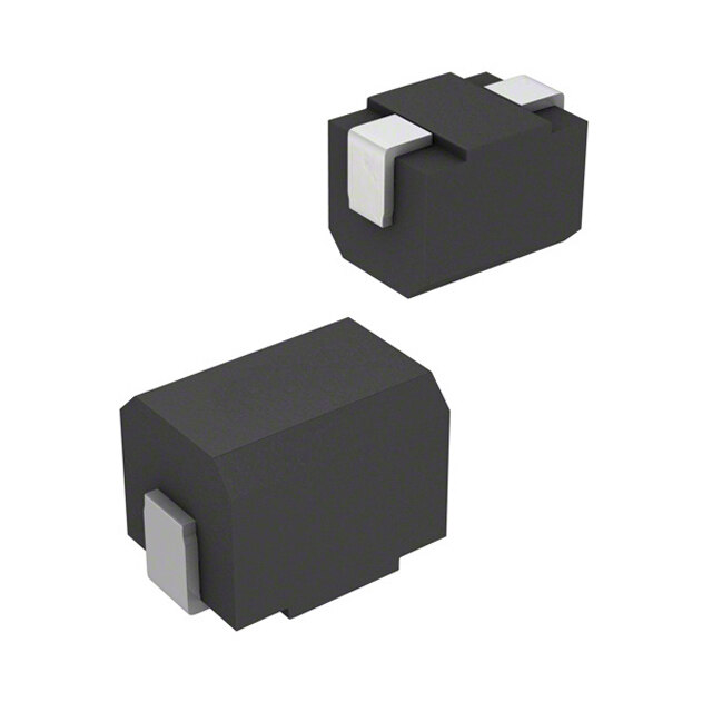
ICGOO在线商城 > 电感器,线圈,扼流圈 > 固定值电感器 > ELJ-FC100JF
- 型号: ELJ-FC100JF
- 制造商: Panasonic Corporation
- 库位|库存: xxxx|xxxx
- 要求:
| 数量阶梯 | 香港交货 | 国内含税 |
| +xxxx | $xxxx | ¥xxxx |
查看当月历史价格
查看今年历史价格
ELJ-FC100JF产品简介:
ICGOO电子元器件商城为您提供ELJ-FC100JF由Panasonic Corporation设计生产,在icgoo商城现货销售,并且可以通过原厂、代理商等渠道进行代购。 ELJ-FC100JF价格参考。Panasonic CorporationELJ-FC100JF封装/规格:固定值电感器, 10µH 无屏蔽 绕线 电感器 80mA 3.7 欧姆最大 1008(2520 公制) 。您可以下载ELJ-FC100JF参考资料、Datasheet数据手册功能说明书,资料中有ELJ-FC100JF 详细功能的应用电路图电压和使用方法及教程。
| 参数 | 数值 |
| 产品目录 | |
| DC电阻(DCR) | 3.7 欧姆最大 |
| 描述 | INDUCTOR 10UH 5% FIXED SMD固定电感器 1008 10uH 5% 80 mA 3.5ohm Wirewound |
| 产品分类 | |
| 品牌 | Panasonic |
| 产品手册 | |
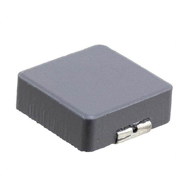
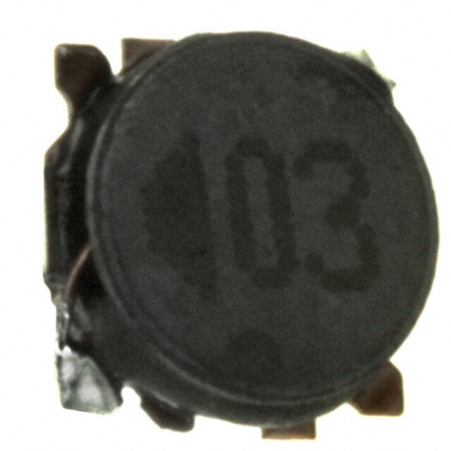
| 产品图片 |
|
| rohs | 符合RoHS无铅 / 符合限制有害物质指令(RoHS)规范要求 |
| 产品系列 | 固定电感器,Panasonic ELJ-FC100JFFC |
| 数据手册 | |
| 产品型号 | ELJ-FC100JF |
| PCN过时产品 | |
| 不同频率时的Q值 | 25 @ 2.52MHz |
| 产品 | Inductors |
| 产品目录绘图 |
|
| 产品目录页面 | |
| 产品种类 | 固定电感器 |
| 供应商器件封装 | 1008 (2520 公制) |
| 其它名称 | PCD1240CT |
| 包装 | 剪切带 (CT) |
| 商标 | Panasonic |
| 外壳宽度 | 2 mm |
| 外壳长度 | 2.5 mm |
| 外壳高度 | 1.6 mm |
| 大小/尺寸 | 0.098" 长x 0.079" 宽(2.50mm x 2.00mm) |
| 安装类型 | 表面贴装 |
| 容差 | 5 % |
| 封装 | Reel |
| 封装/外壳 | 1008(2520 公制) |
| 封装/箱体 | 1008 (2520 metric) |
| 屏蔽 | Unshielded |
| 工作温度 | -20°C ~ 85°C |
| 工厂包装数量 | 2000 |
| 最大直流电流 | 80 mA |
| 最大直流电阻 | 3.5 Ohms |
| 材料-磁芯 | - |
| 标准包装 | 1 |
| 电感 | 10 uH |
| 电流-饱和值 | - |
| 端接类型 | SMD/SMT |
| 类型 | Chip Inductors |
| 系列 | ELJFC |
| 自谐振频率 | 32 MHz |
| 频率-测试 | 2.52MHz |
| 频率-自谐振 | 32MHz |
| 额定电流 | 80mA |
| 高度-安装(最大值) | 0.070" (1.80mm) |





- 商务部:美国ITC正式对集成电路等产品启动337调查
- 曝三星4nm工艺存在良率问题 高通将骁龙8 Gen1或转产台积电
- 太阳诱电将投资9.5亿元在常州建新厂生产MLCC 预计2023年完工
- 英特尔发布欧洲新工厂建设计划 深化IDM 2.0 战略
- 台积电先进制程称霸业界 有大客户加持明年业绩稳了
- 达到5530亿美元!SIA预计今年全球半导体销售额将创下新高
- 英特尔拟将自动驾驶子公司Mobileye上市 估值或超500亿美元
- 三星加码芯片和SET,合并消费电子和移动部门,撤换高东真等 CEO
- 三星电子宣布重大人事变动 还合并消费电子和移动部门
- 海关总署:前11个月进口集成电路产品价值2.52万亿元 增长14.8%



PDF Datasheet 数据手册内容提取
Fixed Inductors (Chip Inductors) 3. General Use FC, FA, FB ■ Features ●General use wire wound, resin molded chip inductor. ●Capable of being Re-flo w or flo w soldered. ●Wide line-up from 2520 to 4532 case sizes. ●Good for mounting. ■ Recommended Applications ●AV equipment, Wireless communication equipment and various types of general electronic equipment. ■ Explanation of Part Numbers 1 2 3 4 5 6 7 8 9 10 11 E L J F A 1 R 2 K F 2 Packaging DesignNo. Productcode Shape Inductance Inductancetolerance F Taping ChipInductors FC 2520(1008) R22 220nH J ±5 % FA 3225(1210) 3R3 3.3µH K ±10 % FB 4532(1812) 470 47µH M ±20 % Size:mm(inch) 561 560µH 102 1000µH ■Storage Conditions ●Package : Normal temperature (–5 to 35 °C), normal humidity (85 %RH max.), shall not be exposed to direct sunlight and harmful gases and care should be taken so as not to cause dew. ●Operating Temperature : –20 to +85 °C ■Storage Period ●Solderability may be reduced due to the conditions of high temperature and high humidity which causes the oxidation of tin-plated terminals. Even if storage conditions are within specifi ed limits, solderability may be reduced with the passage of time. Therefore, please control the storage conditions and try to use the product within 6 months of receipt. ■Packaging Methods Please see Page 127 ■Soldering Conditions Please see Page 128 ■Safety Precautions Please see Page 129 Design and specifi cations are each subject to change without notice. Ask factory for the current technical specific ations before purchase and/or use. Should a safety concern arise regarding this product, please be sure to contact us immediately. 00 Sep. 2010 – 111 –
Fixed Inductors (Chip Inductors) ■ FC Type 2520 (1008) ● ● Dimensions in mm (not to scale) Recommended Land Pattern in mm (not to scale) Marking 6 2 1 1. 0. 0. o ± ± t 0 2 2 2. 1. 1. 2.5+0.3 1.4to1.5 –0.2 3.5to4.0 2 0. ± ■ 6 Standard Packing Quantity 1. ● 2000 pcs./Reel 0.4±0.2 ■ Standard Parts Inductance Q Part No. (µH) Tolerance Test Freq. min. Test Freq. (MSHRzF) m✽1in. ((cid:1)R) DCm ✽a2x. D(mCA C) umrraexn.t (%) (MHz) (MHz) ELJFCR22(cid:1)F 0.22 230 0.70 190 ELJFCR27(cid:1)F 0.27 210 0.75 180 ELJFCR33(cid:1)F 0.33 190 0.85 170 M : ±20 % ELJFCR39(cid:1)F 0.39 175 0.95 160 or 25.2 25.2 ELJFCR47(cid:1)F 0.47 160 1.00 155 ELJFCR56(cid:1)F 0.56 K : ±10 % 155 1.10 150 ELJFCR68(cid:1)F 0.68 135 1.25 140 ELJFCR82(cid:1)F 0.82 125 1.40 130 ELJFC1R0(cid:1)F 1.0 115 0.65 195 ELJFC1R2(cid:1)F 1.2 100 0.75 180 ELJFC1R5(cid:1)F 1.5 90 0.85 170 ELJFC1R8(cid:1)F 1.8 85 0.95 160 ELJFC2R2(cid:1)F 2.2 25 80 1.05 155 ELJFC2R7(cid:1)F 2.7 75 1.20 145 7.96 7.96 ELJFC3R3(cid:1)F 3.3 65 1.30 135 ELJFC3R9(cid:1)F 3.9 60 1.40 130 ELJFC4R7(cid:1)F 4.7 55 1.55 125 ELJFC5R6(cid:1)F 5.6 50 1.75 120 ELJFC6R8(cid:1)F 6.8 45 1.95 115 ELJFC8R2(cid:1)F 8.2 K : ±10 % 40 2.20 105 ELJFC100(cid:1)F 10 or 32 3.70 80 ELJFC120(cid:1)F 12 J : ± 5 % 30 4.10 75 ELJFC150(cid:1)F 15 28 5.00 70 ELJFC180(cid:1)F 18 25 5.40 65 ELJFC220(cid:1)F 22 22 6.00 60 ELJFC270(cid:1)F 27 21 6.30 115 2.52 2.52 ELJFC330(cid:1)F 33 20 7.10 110 ELJFC390(cid:1)F 39 18 9.50 90 ELJFC470(cid:1)F 47 20 17 11.0 80 ELJFC560(cid:1)F 56 16 12.1 75 ELJFC680(cid:1)F 68 15 16.6 70 ELJFC820(cid:1)F 82 13 19.0 65 ELJFC101(cid:1)F 100 0.796 15 0.796 12 21.0 60 (cid:1) : Symbol of Tolerance ✽1 : Self Resonant Frequency ✽2 : DC Resistance Design and specifi cations are each subject to change without notice. Ask factory for the current technical specific ations before purchase and/or use. Should a safety concern arise regarding this product, please be sure to contact us immediately. 00 Sep. 2010 – 112 –
Fixed Inductors (Chip Inductors) ■ FA Type 3225 (1210) ● ● Dimensions in mm (not to scale) Recommended Land Pattern in mm (not to scale) Marking 4 2. 0.2 0.1 to ± ± 9 2.5 1.9 1. 1.6to2.0 3.2±0.3 4.0to4.6 2 ±0. ■ Standard Packing Quantity 2 2. ● 2000 pcs./Reel 0.6±0.2 ■ Standard Parts Inductance Q Part No. (µH) Tolerance Test Freq. min. Test Freq. (MSHRzF) m✽1in. ((cid:1)R) DCm ✽a2x. D(mCA C) umrraexn.t (%) (MHz) (MHz) ELJFAR22(cid:1)F2 0.22 230 0.29 360 ELJFAR27(cid:1)F2 0.27 210 0.32 345 ELJFAR33(cid:1)F2 0.33 M : ±20 % 190 0.35 330 ELJFAR39(cid:1)F2 0.39 175 0.39 305 or 25.2 25 25.2 ELJFAR47(cid:1)F2 0.47 160 0.44 290 ELJFAR56(cid:1)F2 0.56 K : ±10 % 150 0.49 275 ELJFAR68(cid:1)F2 0.68 135 0.55 260 ELJFAR82(cid:1)F2 0.82 125 0.61 245 ELJFA1R0(cid:1)F2 1.0 115 0.69 230 ELJFA1R2(cid:1)F2 1.2 100 0.75 215 ELJFA1R5(cid:1)F 1.5 90 0.75 210 ELJFA1R8(cid:1)F 1.8 85 0.82 200 ELJFA2R2(cid:1)F 2.2 80 0.95 190 ELJFA2R7(cid:1)F 2.7 75 1.1 180 7.96 7.96 ELJFA3R3(cid:1)F 3.3 65 1.2 180 ELJFA3R9(cid:1)F 3.9 60 1.3 175 ELJFA4R7(cid:1)F 4.7 55 1.5 165 ELJFA5R6(cid:1)F 5.6 50 1.6 160 ELJFA6R8(cid:1)F 6.8 45 1.8 150 ELJFA8R2(cid:1)F 8.2 40 2.0 140 30 ELJFA100(cid:1)F 10 36 2.1 140 ELJFA120(cid:1)F 12 K : ±10 % 33 2.5 125 ELJFA150(cid:1)F 15 or 30 2.8 120 ELJFA180(cid:1)F 18 27 3.3 110 J : ± 5 % ELJFA220(cid:1)F 22 25 3.7 105 ELJFA270(cid:1)F 27 22 5.0 90 2.52 2.52 ELJFA330(cid:1)F 33 20 5.6 85 ELJFA390(cid:1)F 39 20 6.4 80 ELJFA470(cid:1)F 47 15 7.0 75 ELJFA560(cid:1)F 56 15 8.0 70 ELJFA680(cid:1)F 68 15 9.0 65 ELJFA820(cid:1)F 82 10 10.0 60 ELJFA101(cid:1)F 100 10 10.0 60 ELJFA121(cid:1)F 120 10 11.0 55 ELJFA151(cid:1)F 150 0.796 20 0.796 8 15.0 50 ELJFA181(cid:1)F 180 7 17.0 50 ELJFA221(cid:1)F 220 7 21.0 45 (cid:1) : Symbol of Tolerance ✽1 : Self Resonant Frequency ✽2 : DC Resistance Design and specifi cations are each subject to change without notice. Ask factory for the current technical specific ations before purchase and/or use. Should a safety concern arise regarding this product, please be sure to contact us immediately. 00 Sep. 2010 – 113 –
Fixed Inductors (Chip Inductors) ■ FB Type 4532 (1812) ● ● Dimensions in mm (not to scale) Recommended Land Pattern in mm (not to scale) Marking 0 3. 0.2 0.2 to ± ± 0 3.2 2.0 2. 2.4to2.6 4.5±0.3 5.5to6.0 2 0. ±2 ■ Standard Packing Quantity 3. ● 500 pcs./Reel 0.6±0.2 ■ Standard Parts Inductance Q Part No. (µH) Tolerance Test Freq. min. Test Freq. (MSHRzF) m✽1in. ((cid:1)R) DCm ✽a2x. D(mCA C) umrraexn.t (%) (MHz) (MHz) ELJFBR22(cid:1)F 0.22 230 0.30 700 ELJFBR27(cid:1)F 0.27 200 0.32 650 ELJFBR33(cid:1)F 0.33 180 0.35 630 ELJFBR39(cid:1)F 0.39 155 0.37 620 M : ±20 % ELJFBR47(cid:1)F 0.47 135 0.40 580 ELJFBR56(cid:1)F 0.56 120 0.42 560 25.2 ELJFBR68(cid:1)F 0.68 30 105 0.48 530 ELJFBR82(cid:1)F 0.82 90 0.50 500 ELJFB1R0(cid:1)F 1.0 80 0.52 470 ELJFB1R2(cid:1)F 1.2 70 0.55 460 ELJFB1R5(cid:1)F 1.5 60 0.61 430 ELJFB1R8(cid:1)F 1.8 50 0.61 410 ELJFB2R2(cid:1)F 2.2 M:±20 % 45 0.61 410 ELJFB2R7(cid:1)F 2.7 43 0.61 400 or 7.96 ELJFB3R3(cid:1)F 3.3 1.0 39 0.66 380 ELJFB3R9(cid:1)F 3.9 K : ±10 % 36 0.74 360 ELJFB4R7(cid:1)F 4.7 33 0.81 350 ELJFB5R6(cid:1)F 5.6 30 0.88 330 ELJFB6R8(cid:1)F 6.8 26 1.0 310 ELJFB8R2(cid:1)F 8.2 24 1.6 250 5 ELJFB100(cid:1)F 10 22 1.8 235 50 ELJFB120(cid:1)F 12 20 1.9 225 ELJFB150(cid:1)F 15 18 2.1 215 ELJFB180(cid:1)F 18 16 2.3 205 ELJFB220(cid:1)F 22 15 2.6 195 ELJFB270(cid:1)F 27 13 2.9 185 ELJFB330(cid:1)F 33 12 3.1 175 ELJFB390(cid:1)F 39 10 3.6 165 ELJFB470(cid:1)F 47 2.52 9.7 4.2 130 ELJFB560(cid:1)F 56 9.0 4.7 125 ELJFB680(cid:1)F 68 8.2 5.3 115 ELJFB820(cid:1)F 82 K : ±10 % 7.5 5.9 110 ELJFB101(cid:1)F 100 or 6.7 8.8 105 ELJFB121(cid:1)F 120 6.1 10 100 J : ± 5 % ELJFB151(cid:1)F 150 40 1.5 5.5 11 95 ELJFB181(cid:1)F 180 5.1 13 85 ELJFB221(cid:1)F 220 4.5 13 85 0.1 ELJFB271(cid:1)F 270 4.1 14 80 ELJFB331(cid:1)F 330 3.7 16 75 ELJFB391(cid:1)F 390 3.3 19 70 ELJFB471(cid:1)F 470 0.796 3.3 31 55 ELJFB561(cid:1)F 560 2.7 35 50 ELJFB681(cid:1)F 680 30 2.5 39 50 ELJFB821(cid:1)F 820 2.4 45 45 ELJFB102(cid:1)F 1000 2.1 53 40 (cid:1) : Symbol of Tolerance ✽1 : Self Resonant Frequency ✽2 : DC Resistance Design and specifi cations are each subject to change without notice. Ask factory for the current technical specific ations before purchase and/or use. Should a safety concern arise regarding this product, please be sure to contact us immediately. 00 Sep. 2010 – 114 –
 Datasheet下载


