ICGOO在线商城 > ELC-09D222F
 Datasheet下载
- 型号: ELC-09D222F
- 制造商: Panasonic Corporation
- 库位|库存: xxxx|xxxx
- 要求:
| 数量阶梯 | 香港交货 | 国内含税 |
| +xxxx | $xxxx | ¥xxxx |
查看当月历史价格
查看今年历史价格
ELC-09D222F产品简介:
ICGOO电子元器件商城为您提供ELC-09D222F由Panasonic Corporation设计生产,在icgoo商城现货销售,并且可以通过原厂、代理商等渠道进行代购。 提供ELC-09D222F价格参考以及Panasonic CorporationELC-09D222F封装/规格参数等产品信息。 你可以下载ELC-09D222F参考资料、Datasheet数据手册功能说明书, 资料中有ELC-09D222F详细功能的应用电路图电压和使用方法及教程。
| 参数 | 数值 |
| 产品目录 | |
| DC电阻(DCR) | 4.4 欧姆 |
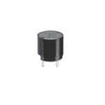
| 描述 | COIL CHOKE 2200UH RADIAL固定电感器 2200uH 10% 170mA 4.4ohm Radial Choke |
| 产品分类 | |
| 品牌 | Panasonic |
| 产品手册 | |
| 产品图片 |
|
| rohs | 符合RoHS无铅 / 符合限制有害物质指令(RoHS)规范要求 |
| 产品系列 | 固定电感器,Panasonic ELC-09D222F09D |
| 数据手册 | |
| 产品型号 | ELC-09D222F |
| 不同频率时的Q值 | - |
| 产品 | Choke Coils |
| 产品培训模块 | http://www.digikey.cn/PTM/IndividualPTM.page?site=cn&lang=zhs&ptm=24863 |
| 产品种类 | 固定电感器 |
| 供应商器件封装 | - |
| 其它名称 | ELC09D222F |
| 包装 | 散装 |
| 商标 | Panasonic |
| 外壳直径 | 9.5 mm |
| 外壳高度 | 8.9 mm |
| 大小/尺寸 | 0.374" 直径(9.50mm) |
| 安装类型 | 通孔 |
| 容差 | 10 % |
| 封装/外壳 | 径向 |
| 屏蔽 | Unshielded |
| 工作温度 | - |
| 工厂包装数量 | 500 |
| 引线直径 | 0.6 mm |
| 引线间隔 | 5 mm |
| 最大直流电流 | 170 mA |
| 最大直流电阻 | 4.4 Ohms |
| 材料-磁芯 | - |
| 标准包装 | 1,000 |
| 测试频率 | 10 kHz |
| 电感 | 2.2 mH |
| 电流-饱和值 | - |
| 端接类型 | Radial |
| 类型 | Choke Coil |
| 系列 | ELC-09 |
| 频率-测试 | 10kHz |
| 频率-自谐振 | - |
| 额定电流 | 170mA |
| 高度-安装(最大值) | 0.350"(8.90mm) |


- 商务部:美国ITC正式对集成电路等产品启动337调查
- 曝三星4nm工艺存在良率问题 高通将骁龙8 Gen1或转产台积电
- 太阳诱电将投资9.5亿元在常州建新厂生产MLCC 预计2023年完工
- 英特尔发布欧洲新工厂建设计划 深化IDM 2.0 战略
- 台积电先进制程称霸业界 有大客户加持明年业绩稳了
- 达到5530亿美元!SIA预计今年全球半导体销售额将创下新高
- 英特尔拟将自动驾驶子公司Mobileye上市 估值或超500亿美元
- 三星加码芯片和SET,合并消费电子和移动部门,撤换高东真等 CEO
- 三星电子宣布重大人事变动 还合并消费电子和移动部门
- 海关总署:前11个月进口集成电路产品价值2.52万亿元 增长14.8%


PDF Datasheet 数据手册内容提取
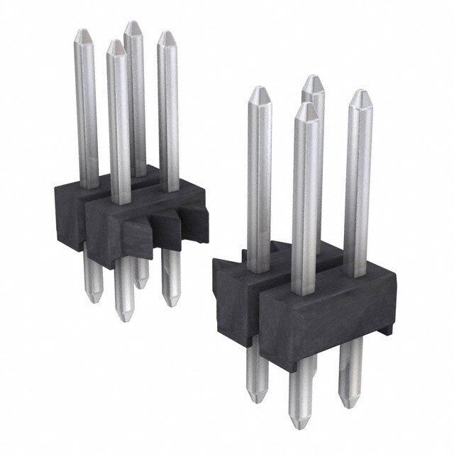
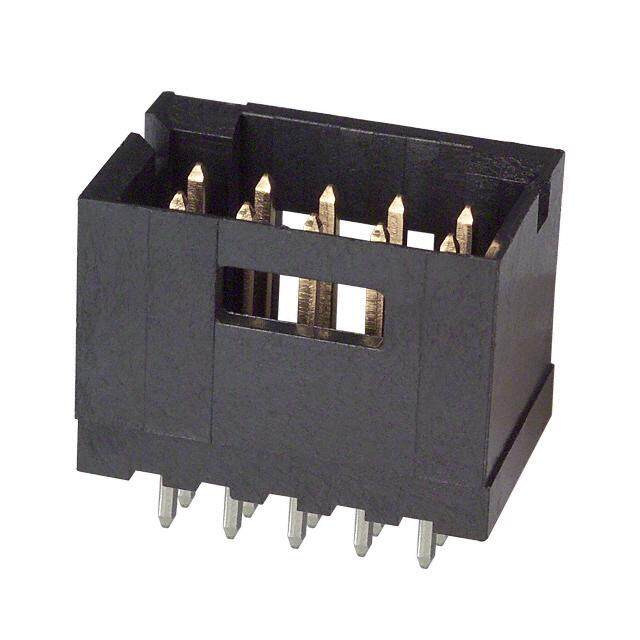
Power Inductors Choke Coils Pin terminal Series : 09D, 11D, 12D, 16B, 18B, Type : Type 09D Type 11D Type 12D 10E, 12E, 15E, 18E Pin terminal inductors featuring small size and high performance Features Type 16B Type 18B Type 10E–L ● High - µ and High Bm cores ● Wide inductor range ● Magnetic shield type (E Type) ● RoHS compliant Recommended Applications ● Appliance, Offi ce automation equipment, Amusement machine, Power circuit for electric Type 12E–L Type 15E–L Type 18E–L device Explanation of Part Numbers 1 2 3 4 5 6 7 8 9 10 11 ✽ E L C 0 9 D 2 R 2 Product code Style Construction Inductance Packaging Design No. 09 Core Core Taping D ✽ E, F etc. D Case 11 Terminal Terminal Other Omission Core size Core 12 Terminal board B Terminal board 15 or Terminal Case size 16 Core (Magnetic Shielded) E Terminal board 18 Terminal Core P Direct terminal by wire Available I-L Characteristics L (µH) L (µH) 10000 10000 5000 5000 10E 12E15E 18E 1000 1000 09D 16B 18B 500 500 100 100 50 50 10 10 5 5 1 1 10 50 100 500 1000 5000 10000 10 50 100 500 1000 5000 10000 IDC(mA) IDC(mA) Design and specifications are each subject to change without notice. Ask factory for the current technical specifications before purchase and/or use. Should a safety concern arise regarding this product, please be sure to contact us immediately. 02 Oct. 2014
Power Inductors Performance Characteristics by Series Extermal Inductance Current Type Construction Dimensions (µH) D×H (mm) 0.1 1.0 10 100 1000 10000 IDC (A) ✽ 09.5×8.9 09D 0.08 to 3.5 (with case) 2.2 10000 ✽ 011.5×13.9 11D 0.16 to 5.3 (with case) 2.2 10000 ar ul 12D 012.5×16.5 0.27 to 1.9 g e R 100 10000 16B 016.0×23.0 0.26 to 8.5 3.3 10000 18B 020.0×27.0 0.36 to 8.5 3.3 10000 10E–L 010.0×13.0 0.10 to 2.9 3.9 8200 12E–L 013.0×18.5 0.13 to 4.4 4.7 10000 d el hi S 016.0×22.0 15E–L 0.30 to 5.4 (3 pin terminal) 5.6 10000 019.0×25.1 18E–L 0.33 to 5.9 (4 pin terminal) 5.6 10000 ✽ : Taping Available Design and specifications are each subject to change without notice. Ask factory for the current technical specifications before purchase and/or use. Should a safety concern arise regarding this product, please be sure to contact us immediately. 02 Oct. 2014
Power Inductors Examples Type 09D R .(Ω) I .✽ Inductance Tolerance Test Freq. DC DC Part No. [at 20 °C] [at 20 °C] (µH) (%) (kHz) (Tol.±20 %) (A)max. [Dimensions in mm] ELC09D2R2□F 2.2 0.012 3.50 (not to scale) ELC09D2R7□F 2.7 0.013 3.30 ELC09D3R3□F 3.3 0.015 3.20 f9.5 max. ELC09D3R9□F 3.9 0.016 3.10 ELC09D4R7□F 4.7 0.018 3.00 ELC09D5R6□F 5.6 0.019 2.90 ax. ±20 m ELC09D6R8□F 6.8 0.021 2.80 9 8. ELC09D8R2□F 8.2 0.024 2.60 1.0 ELC09D100□F 10.0 0.027 2.50 ± 4.0 ELC09D120□F 12.0 0.031 2.30 5.0±0.5 ELC09D150□F 15.0 0.035 2.10 2–f0.6 ELC09D180□F 18.0 0.038 2.00 ELC09D220□F 22.0 0.051 1.80 ELC09D270□F 27.0 0.058 1.60 ELC09D330□F 33.0 0.081 1.40 ELC09D390□F 39.0 0.087 1.30 ELC09D470□F 47.0 0.110 1.20 ELC09D560□F 56.0 0.130 1.10 ELC09D680□F 68.0 0.140 1.00 Recommended PWB piercing plan ELC09D820□F 82.0 0.160 0.90 ELC09D101□F 100.0 0.200 0.82 ELC09D121□F 120.0 0.250 0.77 ELC09D151□F 150.0 10 0.320 0.74 ELC09D181□F 180.0 0.360 0.61 2–f1.00±0.05 ELC09D221□F 220.0 0.410 0.58 ELC09D271□F 270.0 0.500 0.52 5.0±0.1 ELC09D331□F 330.0 0.650 0.49 ELC09D391□F 390.0 0.860 0.46 ELC09D471□F 470.0 ±10 0.980 0.39 ELC09D561□F 560.0 1.100 0.36 ELC09D681□F 680.0 1.400 0.34 Connection Schematic ELC09D821□F 820.0 1.600 0.30 ELC09D102□F 1000.0 2.100 0.28 ELC09D122□F 1200.0 2.400 0.23 ELC09D152□F 1500.0 2.800 0.21 S ELC09D182□F 1800.0 3.800 0.19 ELC09D222□F 2200.0 4.400 0.17 ELC09D272□F 2700.0 6.100 0.16 F ELC09D332□F 3300.0 7.000 0.14 ELC09D392□F 3900.0 8.000 0.13 ELC09D472□F 4700.0 11.200 0.12 ELC09D562□F 5600.0 12.600 0.11 ELC09D682□F 6800.0 14.400 0.10 ELC09D822□F 8200.0 16.600 0.09 ELC09D103□F 10000.0 18.800 0.08 ✽ Allowable DC Current: Smaller current value either when the inductance is –10 % or when the case temperature has risen 45 °C. Design and specifications are each subject to change without notice. Ask factory for the current technical specifications before purchase and/or use. Should a safety concern arise regarding this product, please be sure to contact us immediately. 02 Oct. 2014
Power Inductors Examples Type 11D R. .(Ω) I .✽ Inductance Tolerance Test Freq. DC DC Part No. [at 20 °C] [at 20 °C] (µH) (%) (kHz) (Tol.±20 %) (A)max. [Dimensions in mm] ELC11D2R2□F 2.2 0.013 5.30 (not to scale) ELC11D2R7□F 2.7 0.014 5.10 ELC11D3R3□F 3.3 0.015 4.90 f11.5 max. ELC11D3R9□F 3.9 0.016 4.80 ELC11D4R7□F 4.7 0.018 4.70 x. ELC11D5R6□F 5.6 0.020 4.60 a ±20 9 m ELC11D6R8□F 6.8 0.022 4.40 13. ELC11D8R2□F 8.2 0.024 3.90 1.0 ELC11D100□F 10.0 0.029 3.50 ± 3.5 ELC11D120□F 12.0 0.030 3.40 5.0±0.5 ELC11D150□F 15.0 0.033 3.30 2–f0.6 ELC11D180□F 18.0 0.037 3.10 ELC11D220□F 22.0 0.040 2.80 ELC11D270□F 27.0 0.048 2.70 ELC11D330□F 33.0 0.051 2.60 ELC11D390□F 39.0 0.057 2.50 ELC11D470□F 47.0 0.063 2.30 ELC11D560□F 56.0 0.071 2.10 ELC11D680□F 68.0 0.082 2.00 ELC11D820□F 82.0 0.090 1.90 Recommended PWB ELC11D101□F 100.0 0.120 1.80 piercing plan ELC11D121□F 120.0 0.160 1.60 ELC11D151□F 150.0 10 0.180 1.40 2–f1.00±0.05 ELC11D181□F 180.0 0.200 1.30 ELC11D221□F 220.0 0.230 1.20 ELC11D271□F 270.0 0.320 1.10 5.0±0.1 ELC11D331□F 330.0 0.350 1.00 ELC11D391□F 390.0 0.400 0.95 ELC11D471□F 470.0 ±10 0.490 0.82 ELC11D561□F 560.0 0.620 0.73 ELC11D681□F 680.0 0.780 0.64 Connection Schematic ELC11D821□F 820.0 0.870 0.62 ELC11D102□F 1000.0 1.100 0.57 ELC11D122□F 1200.0 1.200 0.52 ELC11D152□F 1500.0 1.700 0.43 S ELC11D182□F 1800.0 2.000 0.40 ELC11D222□F 2200.0 2.300 0.38 ELC11D272□F 2700.0 2.800 0.34 F ELC11D332□F 3300.0 3.600 0.31 ELC11D392□F 3900.0 4.500 0.29 ELC11D472□F 4700.0 5.200 0.26 ELC11D562□F 5600.0 6.900 0.23 ELC11D682□F 6800.0 7.800 0.21 ELC11D822□F 8200.0 10.600 0.18 ELC11D103□F 10000.0 11.800 0.16 ✽ Allowable DC Current: Smaller current value either when the inductance is –10 % or when the case temperature has risen 45 °C. Design and specifications are each subject to change without notice. Ask factory for the current technical specifications before purchase and/or use. Should a safety concern arise regarding this product, please be sure to contact us immediately. 03 Jun. 2016
Power Inductors Examples Type 12D R .(Ω) I .✽ Inductance Tolerance Test Freq. DC DC Part No. [at 20 °C] [at 20 °C] (µH) (%) (kHz) (Tol.±20 %) (A)max. ELC12D101E 100 0.150 1.90 [Dimensions in mm] (not to scale) ELC12D121E 120 0.170 1.78 14.0 max. f12.0±0.5 ELC12D151E 150 0.190 1.67 ELC12D181E 180 0.210 1.58 x. ELC12D221E 220 0.230 1.55 a m 5 ELC12D271E 270 0.270 1.44 6. 1 ELC12D331E 330 0.300 1.34 ELC12D391E 390 0.330 1.32 f0.8 8 0. 7.5±0.5 ELC12D471E 470 0.380 1.25 ± 5 3. ELC12D561E 560 0.420 1.15 ELC12D681E 680 0.460 0.98 ELC12D821E 820 0.650 0.94 ELC12D102E 1000 ±10 10 0.720 0.87 ELC12D122E 1200 0.830 0.86 Recommended PWB piercing plan ELC12D152E 1500 1.270 0.64 2–f1.20±0.05 ELC12D182E 1800 1.330 0.63 ELC12D222E 2200 1.500 0.60 7.5±0.1 ELC12D272E 2700 1.890 0.54 ELC12D332E 3300 2.370 0.48 Connection Schematic ELC12D392E 3900 2.830 0.45 S ELC12D472E 4700 3.190 0.41 ELC12D562E 5600 4.080 0.34 ELC12D682E 6800 5.740 0.29 F ELC12D822E 8200 6.340 0.28 ELC12D103E 10000 7.200 0.27 ✽ Allowable DC Current: Smaller current value either when the inductance is –10 % or when the case temperature has risen 45 °C. Design and specifications are each subject to change without notice. Ask factory for the current technical specifications before purchase and/or use. Should a safety concern arise regarding this product, please be sure to contact us immediately. 02 Oct. 2014
Power Inductors Examples Type 16B RDC.(Ω) I .✽ Inductance Tolerance Test Freq. [at 20 °C] DC Part No. (µH) (%) (kHz) (Tol.±30 %)✽✽ [at 20 °C] (A)max. (Tol.±20 %) ✽✽ [Dimensions in mm] ELC16B3R3L 3.3 0.012 8.50 ±25 (not to scale) ELC16B3R9L 3.9 0.013✽✽ 8.00 ✽✽ ELC16B4R7L 4.7 0.015 7.80 16.0 max. ✽✽ ELC16B5R6L 5.6 0.016 7.40 f 13.0±0.5 ELC16B6R8L 6.8 0.018 6.70 ELC16B8R2L 8.2 0.019 6.10 ±20 ELC16B100L 10.0 0.022 5.60 ax. ELC16B120L 12.0 0.023 5.50 m 3.0 ELC16B150L 15.0 0.026 5.40 2 ELC16B180L 18.0 0.028 5.10 ELC16B220L 22.0 0.031 4.60 ELC16B270L 27.0 0.034 4.30 5 f 1.0 0. ELC16B330L 33.0 0.039 4.00 ± 5 7.5±0.5 4. ELC16B390L 39.0 0.042 3.90 ELC16B470L 47.0 0.045 3.80 ELC16B560L 56.0 0.051 3.40 ELC16B680L 68.0 0.057 3.20 ELC16B820L 82.0 0.064 3.00 ELC16B101L 100.0 0.072 2.60 ELC16B121L 120.0 0.080 2.50 Recommended PWB ELC16B151L 150.0 0.103 2.20 piercing plan ELC16B181L 180.0 10 0.115 2.10 ELC16B221L 220.0 0.130 1.90 ELC16B271L 270.0 0.170 1.60 ELC16B331L 330.0 0.200 1.50 2–f 1.50±0.05 ELC16B391L 390.0 0.250 1.30 ELC16B471L 470.0 ±10 0.280 1.20 ELC16B561L 560.0 0.380 1.10 7.5±0.1 ELC16B681L 680.0 0.430 1.00 ELC16B821L 820.0 0.580 0.88 ELC16B102L 1000.0 0.660 0.85 ELC16B122L 1200.0 0.740 0.82 Connection Schematic ELC16B152L 1500.0 0.870 0.74 ELC16B182L 1800.0 1.220 0.60 ELC16B222L 2200.0 1.380 0.57 ELC16B272L 2700.0 1.570 0.54 S ELC16B332L 3300.0 2.000 0.47 ELC16B392L 3900.0 2.400 0.42 ELC16B472L 4700.0 3.300 0.36 F ELC16B562L 5600.0 3.700 0.34 ELC16B682L 6800.0 4.200 0.32 ELC16B822L 8200.0 5.600 0.28 ELC16B103L 10000.0 6.400 0.26 ✽ Allowable DC Current: Smaller current value either when the inductance is –10 % or when the case temperature has risen 45 °C. Design and specifications are each subject to change without notice. Ask factory for the current technical specifications before purchase and/or use. Should a safety concern arise regarding this product, please be sure to contact us immediately. 02 Oct. 2014
Power Inductors Examples Type 18B R .(Ω) I .✽ Inductance Tolerance Test Freq. DC DC Part No. [at 20 °C] [at 20 °C] (µH) (%) (kHz) (Tol.±20 %) (A)max. [Dimensions in mm] ELC18B3R3L 3.3 0.010 8.50 (not to scale) ELC18B3R9L 3.9 0.011 8.00 ELC18B4R7L 4.7 0.012 7.80 20.0 max. ELC18B5R6L 5.6 0.013 7.40 f 16.0 max. ELC18B6R8L 6.8 0.015 6.80 ±20 ELC18B8R2L 8.2 0.016 6.60 ELC18B100L 10.0 0.017 6.50 x. ELC18B120L 12.0 0.018 6.00 a m ELC18B150L 15.0 0.021 5.90 0 27. ELC18B180L 18.0 0.022 5.60 ELC18B220L 22.0 0.025 5.40 ELC18B270L 27.0 0.028 4.80 ELC18B330L 33.0 0.030 4.60 ±1 f 1.0 5.0 7.5±0.5 ELC18B390L 39.0 0.033 4.40 ELC18B470L 47.0 0.037 4.30 ax. ELC18B560L 56.0 0.040 4.20 m 0 ELC18B680L 68.0 0.046 4.00 8. 1 f ELC18B820L 82.0 0.051 3.70 ELC18B101L 100.0 0.057 3.20 ELC18B121L 120.0 0.065 3.00 Recommended PWB ELC18B151L 150.0 0.072 2.70 piercing plan ELC18B181L 180.0 10 0.082 2.60 ELC18B221L 220.0 0.090 2.40 ELC18B271L 270.0 0.110 2.20 ELC18B331L 330.0 0.130 1.90 2–f 1.50±0.05 ELC18B391L 390.0 0.150 1.80 ELC18B471L 470.0 ±10 0.210 1.60 ELC18B561L 560.0 0.230 1.50 7.5±0.1 ELC18B681L 680.0 0.260 1.40 ELC18B821L 820.0 0.340 1.30 ELC18B102L 1000.0 0.390 1.10 ELC18B122L 1200.0 0.440 1.00 Connection Schematic ELC18B152L 1500.0 0.580 0.85 ELC18B182L 1800.0 0.650 0.84 ELC18B222L 2200.0 0.880 0.75 ELC18B272L 2700.0 1.200 0.68 S ELC18B332L 3300.0 1.400 0.60 ELC18B392L 3900.0 1.500 0.57 ELC18B472L 4700.0 1.700 0.55 F ELC18B562L 5600.0 2.200 0.46 ELC18B682L 6800.0 2.800 0.45 ELC18B822L 8200.0 3.100 0.41 ELC18B103L 10000.0 3.900 0.36 ✽ Allowable DC Current: Smaller current value either when the inductance is –10 % or when the case temperature has risen 45 °C. Design and specifications are each subject to change without notice. Ask factory for the current technical specifications before purchase and/or use. Should a safety concern arise regarding this product, please be sure to contact us immediately. 02 Oct. 2014
Power Inductors Tape Dimensions in mm for Type 09D (not to scale) Tape Dimensions in mm for Type 11D (not to scale) f9.5 max. 1.3 max. 1.3 max. 2.0 max. 2.0 max. f11.5 max. 1.3 max. 1.3 max. 2.0 max. 2.0 max. Marking 12.7 Marking 12.7 max. 18.038.9 max..85 5.0 3.0 max. max. 18.0313.9 max..85 5.0 3.0 max. 11.0 9.05.0 min.18.0 0.6 11.0 9.05.0 min.18.0 0.6 max. 12.7 5.0±1.0 f4.0 druirTneancpiteniogn max. 12.7 5.0±1.0 f4.0 druirTneancpiteniogn 1.0 1.0 500 pcs./reel 500 pcs./reel Safety Precautions • When using our products, no matter what sort of equipment they might be used for, be sure to make a written agreement on the specifications with us in advance. The design and specifications in this catalog are subject to change without prior notice. • Do not use the products beyond the specifications described in this catalog. • This catalog explains the quality and performance of the products as individual components. Be fore use, check and evaluate their operations when installed in your products. • Install the following systems for a failsafe design to ensure safety if these products are to be used in equip ment where a defect in these products may cause the loss of human life or other significant damage, such as damage to vehicles (aut om ob ile, train, vessel), traffic lights, medical equipment, aerospace equipment, elect ric heating ap pli anc es, comb us tion/gas equipment, rotating equipment, and disaster/crime prevention equipm ent. ✽ Systems equipped with a protection circuit and a protection device ✽ Systems equipped with a redundant circuit or other system to prevent an unsafe status in the event of a single fault Precautions for use 1. Rated current The rated current is defined as the smaller value of eit her the current value when the inductance drops 10 % down from its initial point, or when the average temperature of coil interior rises 45 °C up on powe r source. Do not operate these coils beyond the specified rate d current. 2. Mounting 1 Cores may be damaged when exc es sive force or shock is applied. Do not use products which may have been dropped. 2 Be careful not to make contact with other parts and consider possible interaction between coils due to magnetic interference. 3 Be careful of being too close to heat-radiating parts (high temperature). 4 Do not bend the pin-terminals during assembly. The pin-terminals must connect correctly. Do not apply them a shock to avoid causing an open or short circuit condition. 5 The float on PWB must not be after mounting. 3. Soldering 1 Use flux which will not effect copper wire. (Be sure to use proper amounts of chloride, pH and other solvents) 2 When using a soldering iron, wait at least 3 minutes before attempting to re-solder. 4. Storage 1 Avoid high temperatures, high moisture, gases and magnetic fields. 2 For long term storage of more than 1 year, use the prod ucts only after inspecting their outer structure. (Look for possible rusting of the core and oxidation of the lead wire, which would affect its solderability.) <Package markings> Package markings include the product number, quantity, and country of origin. In principle, the country of origin should be indicated in English. Design and specifications are each subject to change without notice. Ask factory for the current technical specifications before purchase and/or use. Should a safety concern arise regarding this product, please be sure to contact us immediately. 02 Oct. 2014
Mouser Electronics Authorized Distributor Click to View Pricing, Inventory, Delivery & Lifecycle Information: P anasonic: ELC-09D100DF ELC-09D101DF ELC-18B221L ELC-18B101L ELC-09D180F ELC-09D101F ELC-09D102DF ELC-09D103DF ELC-09D103F ELC-09D120DF ELC-09D120F ELC-09D121DF ELC-09D121F ELC-09D122DF ELC-09D122F ELC-09D150DF ELC-09D151DF ELC-09D151F ELC-09D152DF ELC-09D152F ELC-09D180DF ELC-09D181DF ELC-09D181F ELC-09D182DF ELC-09D182F ELC-09D220DF ELC-09D221DF ELC-09D221F ELC-09D222DF ELC-09D270DF ELC-09D270F ELC-09D271DF ELC-09D271F ELC-09D272DF ELC-09D272F ELC-09D2R2DF ELC-09D2R2F ELC-09D2R7DF ELC-09D2R7F ELC-09D330DF ELC-09D330F ELC-09D331DF ELC-09D332DF ELC-09D332F ELC-09D390DF ELC-09D390F ELC-09D391DF ELC-09D391F ELC-09D392DF ELC-09D392F ELC-09D3R3DF ELC-09D3R9DF ELC-09D470DF ELC-09D471DF ELC-09D472DF ELC-09D472F ELC-09D560DF ELC-09D560F ELC-09D561DF ELC-09D561F ELC-09D562DF ELC-09D562F ELC-09D5R6DF ELC-09D5R6F ELC-09D680DF ELC-09D681DF ELC-09D681F ELC-09D682DF ELC-09D682F ELC-09D6R8DF ELC-09D820DF ELC-09D820F ELC-09D821DF ELC-09D821F ELC-09D822DF ELC-09D822F ELC-09D8R2DF ELC-09D8R2F ELC-10E120L ELC-10E221L ELC-10E330L ELC-10E332L ELC-10E391L ELC-10E471L ELC- 12D101E ELC-12D102E ELC-12D103E ELC-12D121E ELC-12D122E ELC-12D151E ELC-12D152E ELC-12D181E ELC-12D182E ELC-12D221E ELC-12D222E ELC-12D271E ELC-12D272E ELC-12D331E ELC-12D332E ELC- 12D391E