
 Datasheet下载
- 型号: ECW1J-B24-BC0024L
- 制造商: Bourns
- 库位|库存: xxxx|xxxx
- 要求:
| 数量阶梯 | 香港交货 | 国内含税 |
| +xxxx | $xxxx | ¥xxxx |
查看当月历史价格
查看今年历史价格
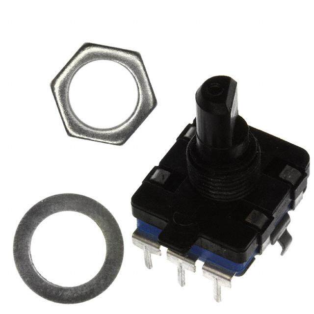
ECW1J-B24-BC0024L产品简介:
ICGOO电子元器件商城为您提供ECW1J-B24-BC0024L由Bourns设计生产,在icgoo商城现货销售,并且可以通过原厂、代理商等渠道进行代购。 ECW1J-B24-BC0024L价格参考¥20.55-¥49.93。BournsECW1J-B24-BC0024L封装/规格:编码器, 。您可以下载ECW1J-B24-BC0024L参考资料、Datasheet数据手册功能说明书,资料中有ECW1J-B24-BC0024L 详细功能的应用电路图电压和使用方法及教程。
Bourns Inc.生产的ECW1J-B24-BC0024L编码器是一款高精度、可靠的旋转编码器,广泛应用于各种工业和自动化设备中。以下是该型号编码器的主要应用场景:

 1. 工业自动化
   在工业自动化系统中,ECW1J-B24-BC0024L编码器常用于精确控制电机的转速和位置。它能够提供高分辨率的反馈信号,帮助控制系统实时监测电机的运行状态,确保设备的稳定性和精度。例如,在数控机床(CNC)中,编码器可以精确控制刀具的进给速度和位置,保证加工精度。

 2. 机器人技术
   编码器在机器人关节处的应用非常普遍。ECW1J-B24-BC0024L可以安装在机器人的各个关节部位,提供角度反馈,帮助机器人实现精准的动作控制。无论是工业机器人还是服务机器人,编码器都能确保机器人手臂或腿部的运动更加平稳和准确。

 3. 输送系统
   在物流和生产线上,编码器用于监控传送带的速度和位置。通过安装在电机轴上的编码器,系统可以实时获取传送带的运行状态,确保货物的准确运输和分拣。此外,编码器还可以帮助检测传送带是否出现打滑或停转等异常情况,及时发出警报。

 4. 医疗设备
   在医疗设备中,如手术机器人、X光机、CT扫描仪等,编码器用于精确控制机械部件的运动。ECW1J-B24-BC0024L编码器的高精度特性使其非常适合用于这些对精度要求极高的场合,确保设备的安全性和可靠性。

 5. 智能家居与家电
   在智能家居和家电领域,编码器可以用于控制风扇、空调、洗衣机等设备的电机。通过编码器提供的反馈,设备可以根据实际需求调整电机的转速,从而实现节能和提高用户体验。

 6. 汽车电子
   在汽车电子系统中,编码器可用于电动助力转向系统(EPS)、自动变速器等部件。ECW1J-B24-BC0024L编码器能够提供精确的角度和速度反馈,帮助车辆实现更平顺的操作和更高的安全性。

总之,ECW1J-B24-BC0024L编码器凭借其高精度、可靠性和耐用性,适用于多种需要精确位置和速度控制的场景,尤其是在工业自动化、机器人技术和医疗设备等领域表现尤为突出。
| 参数 | 数值 |
| 产品目录 | |
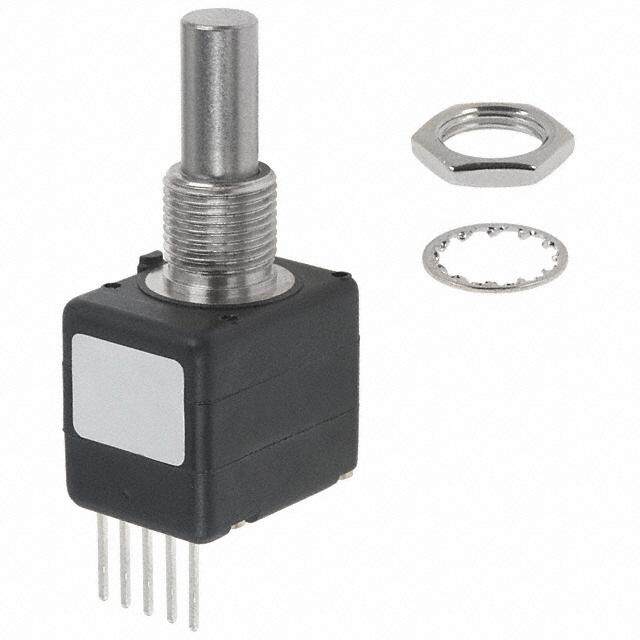
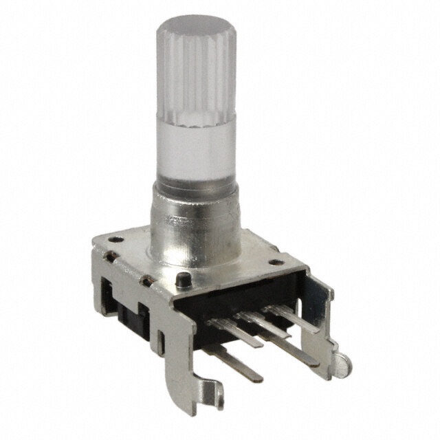
| 描述 | ENCODER DIGITAL CONT 24 CPR编码器 9mm Inserted Slot |
| 产品分类 | |
| 品牌 | Bourns Inc. |
| 产品手册 | |
| 产品图片 |
|
| rohs | 符合RoHS无铅 / 符合限制有害物质指令(RoHS)规范要求 |
| 产品系列 | Bourns ECW1J-B24-BC0024LECW |
| 数据手册 | |
| 产品型号 | ECW1J-B24-BC0024L |
| PCN设计/规格 | |
| 产品 | Mechanical Encoders |
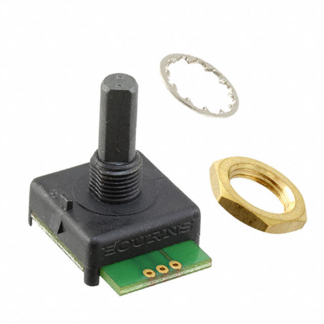
| 产品目录绘图 |
|
| 产品目录页面 | |
| 产品种类 | |
| 其它名称 | ECW1JB24BC0024L |
| 内置开关 | 无 |
| 分辨率 | 24 PPR |
| 制动器数量 | 24 Detent |
| 商标 | Bourns |
| 大小/尺寸 | 28.5 mm x 22 mm |
| 套管材料 | Plastic |
| 套管螺纹 | M9 x 0.75 |
| 安装类型 | 面板,PCB 通孔 |
| 安装风格 | - |
| 封装 | Bulk |
| 工作温度范围 | - 40 C to + 85 C |
| 工厂包装数量 | 45 |
| 带开关 | No Switch |
| 技术 | Rotary |
| 旋转寿命(最少次数) | 200K |
| 朝向 | 垂直 |
| 标准包装 | 45 |
| 棘爪 | 是 |
| 每转脉冲数 | 24 |
| 电压-电源 | - |
| 电源电压 | - |
| 端子类型 | PC 引脚 |
| 端接类型 | Through Hole |
| 类型 | Incremental |
| 系列 | ECW |
| 编码器类型 | 机械 |
| 致动器类型 | 1/4" 直径开槽端头 |
| 衬套大小 | 9 mm x 6.35 mm |
| 轴直径 | 1/4 in |
| 轴类型 | Slotted |
| 轴长度 | 3/4 in |
| 输出 | Quadrature |
| 输出类型 | 正交(增量) |
| 通道数量 | 2 Channel |


- 商务部:美国ITC正式对集成电路等产品启动337调查
- 曝三星4nm工艺存在良率问题 高通将骁龙8 Gen1或转产台积电
- 太阳诱电将投资9.5亿元在常州建新厂生产MLCC 预计2023年完工
- 英特尔发布欧洲新工厂建设计划 深化IDM 2.0 战略
- 台积电先进制程称霸业界 有大客户加持明年业绩稳了
- 达到5530亿美元!SIA预计今年全球半导体销售额将创下新高
- 英特尔拟将自动驾驶子公司Mobileye上市 估值或超500亿美元
- 三星加码芯片和SET,合并消费电子和移动部门,撤换高东真等 CEO
- 三星电子宣布重大人事变动 还合并消费电子和移动部门
- 海关总署:前11个月进口集成电路产品价值2.52万亿元 增长14.8%


PDF Datasheet 数据手册内容提取
Features NT MPLIA ■ Incremental encoder / quadrature output HS CO ■ Exceptionally long operating life Ro ■ Sturdy construction * ■ Bushing mount ■ Available with PC board mounting bracket (optional) ■ RoHS compliant* ECW - Digital Contacting Encoder Electrical Characteristics Output ..................................................................................2-bit quadrature code, Channel A leads Channel B by 90 º electrically turning clockwise (CW) Closed Circuit Resistance ...........................................................................................................................................................................5 ohms maximum Open Circuit Resistance .......................................................................................................................................................................100 K ohms minimum Contact Rating ..................................................................................................................................................10 milliamp @ 10 VDC or 0.1 watt maximum Insulation Resistance (500 VDC) ...................................................................................................................................................1,000 megohms minimum Dielectric Withstanding Voltage (MIL-STD-202 Method 301) Sea Level ............................................................................................................................................................................................1,000 VAC minimum Electrical Travel .....................................................................................................................................................................................................Continuous Contact Bounce (15 RPM)................................................................................................................................................................5 milliseconds maximum RPM (Operating) ..............................................................................................................................................................................................120 maximum Phase Tolerance (CH A to CH B) ............................................................................................................................................................................90 ° ± 72 ° Environmental Characteristics Operating Temperature Range .........................................................................................................................................-40 ºC to +85 ºC (-40 °F to 185 °F) Storage Temperature Range ..........................................................................................................................................-40 ºC to +85 ºC (-40 °F to +185 °F) Humidity.................................................................................................................................................................MIL-STD-202, Method 103B, Condition B Vibration ..........................................................................................................................................................................................................................15 G Contact Bounce ...........................................................................................................................................................................0.1 millisecond maximum Shock...............................................................................................................................................................................................................................50 G Contact Bounce ...........................................................................................................................................................................0.1 millisecond maximum Rotational Life..................................................................................................................................................................................200,000 shaft revolutions IP Rating ..........................................................................................................................................................................................................................IP 40 Mechanical Characteristics Mechanical Angle ..................................................................................................................................................................................................Continuous Running Torque (Detented) ............................................................................................................................................0.5 to 1.5 N-cm (0.75 to 2.25 oz-in.) Undetented Torque ........................................................................................................................................................0.17 to 1.0 N-cm (0.25 to 1.50 oz-in) Mounting Torque .........................................................................................................................................................................79 N-cm (7 lb.-in.) maximum Shaft Side Load (Static)....................................................................................................................................................................4.5 kg (10 lbs.) minimum Weight ................................................................................................................................................................................Approximately 21 gms. (0.75 oz.) Terminals .................................................................................................................................................................................................PC pin or solder lug Soldering Condition Manual Soldering ...................................................................................................................96.5Sn/3.0Ag/0.5Cu solid wire or no-clean rosin cored wire 370 °C (700 °F) max. for 3 seconds Wave Soldering ...........................................................................................................................................96.5Sn/3.0Ag/0.5Cu solder with no-clean fl ux 260 °C (500 °F) max. for 5 seconds Wash processes ....................................................................................................................................................................................Not recommended Marking ...........................................................................................................................Manufacturer’s name and trademark, part number, and date code. Hardware .................................................One lockwasher and one mounting nut are shipped with each encoder, except where noted in the part number. Quadrature Output Table – This table is intended to show available outputs as currently defi ned. 1/4 CYCLE PER DETENT FULL CYCLE PER DETENT (Normally Open in Detent Shown) CW Channel A CW Channel A Closed Circuit Closed Circuit Open Circuit Open Circuit Closed Circuit Closed Circuit Open Circuit Open Circuit D D D D D D D D D D D D D D D D D D D D D D Channel B CCW Channel B CCW RECOMMENDED INCREMENTAL CONTROL DIAGRAM FOR USE WITH A DEBOUNCE CIRCUIT (CUSTOMER LOGIC CIRCUITRY) 7 9 DIRECTION 5 ms DELAY DEBOUNCE DECODE UP/DOWN BINARY (MC 14490) LOGIC COUNTER OUTPUT MAGNITUDE *RoHS Directive 2002/95/EC Jan. 27, 2003 including annex and RoHS Recast 2011/65/EU June 8, 2011. Specifi cations are subject to change without notice. The device characteristics and parameters in this data sheet can and do vary in different applications and actual device performance may vary over time. Users should verify actual device performance in their specifi c applications.
ECW - Digital Contacting Encoder Dimensional Drawings BUSHING MOUNTED - HOUSING A PANEL HOLE DIMENSIONS Rear-Facing Terminals “L” ± 0.38 Bushing Mounted (“L” ± .015) 22.2 ± 0.25 8.51 6.35 (.874 ± .010) (.335) (.250) 9.52 9.14 (1.413.17) 27.68 ± 0.25 (.375) (.360)DIA. (1.090 ± .010) 9.0 DIA. (.1547.87 ±± .00.250)DIA. 28.49 ± 0.25 (3.1.1275)DIA. (.354) (1.122 ± .010) 1.52 M9 X 0.75-6g SPL ACB 5.69 ± 0.25 (.224 ± .010) (.060) CHANNEL A COMMONCHANNEL B PCB BRACKET MOUNTED - HOUSING B PCB MOUNTING DIMENSIONS SOLDER HOLES - HOUSING C Dimensions not given are the same as Bushing Mounted. (Housing Styles B and E) Dimensions not given are the same as Bushing Mounted. 28.499 ± .254 5.74 9.02 23.37 ± 0.25 CL (1.122 ± .010) (.226) (.355) (.920 ± .010) 11.4 15.2 (.450) .762 (.600) 2.54 (.030) 17.069 23.6 (.100)TYP. 16.002 4 PLCS. (.672) (.930) 1.2 (.630) (.047)DIA. 7 PLCS. 2.54 A C B (6.2.3550 ±± 0.0.2150) CHANNEL A COAMCMBONCHANNEL B (1.0.5672) (.1(05.02.)0080) 3( ..P10L04C72S)D.IA. SNAP-IN MOUNT - Housing G PCB MOUNTING DIMENSIONS 13.08 “L” ± 0.38 22.68 (.515) (“L” ± .015) (.893) (8.3.5315)6.35 (2.28.7240 ±± .00.1205) 9.53 (104.5.6788 ±± 50..0280)DIA. (1.14.4363) (.375) (.250) 27.69 ± 0.25 (1.090 ± .010) 21.11 11.10 28.50 ± 0.25 .97 (.831) 8.99 (.437) (1.122 ± .010) 8 X(.038)R (.354) 3 X .635 (7.2.2845 ±± 0.0.2150) (1.0.5620) DIA. CHANNEL A COMMONCHANNEL B ((5..20.002805)) (2.1.5040) 2 X(2.1.5040)3 X(01..00472)(1.04.2990) (1.24.8224) (1.97.7786) Shaft Style B Shaft Style C Shaft Style J Shaft Style R Shaft Style Y 4.75 ± .006/-.051 (6.2.3429 ++ 0.0.0031//–– 0.0.0063)DIA. (5.2.5148 ±± ..007063) (4.1.0518 ++ ..005012// –– ..002051) (.187 + .003/-.002)DIA. (0.0.9442) (6.2.0306 ±± ..102075) (1.0.5672) (.41.875) DIA. DIA. DIA. (.10.663) (1.0.1497) "D" DIMEN"DS"ION EXTEND(6.2S.34 F29R ++O 0.0M.00 31S//H–– A0.0F.00T63 )END TO BUSHIN"GD" FACE (0.0.3781) (.10.663) (.10.1497) S< L1O "T L DEENPGTTHH ( " Y 1 " 4 S . 7 H A FFTO)R ( S 9. 3 H. 68 A 50 F ) T SF O≥R 1 S "H LAEFNTGST H "D" = (SHAFT LENGTH, FMS) – (BUSHING LENGTH) (.578) BUSHING MOUNTED - HOUSING H 23.87 Front-Facing Terminals (.940) 15.87 ±.038 .25 .13 22.2 ±.025 (.625 ±.015) (.010) (.005) (.874 ±.010) 9.01 ±.020 6.35 8.50 ±.025 1.52 (.355 ±.008) 4.01 +.050/-.025 (.250) (.335 ±.010) MM (.060) 1.19 11.09 (.158 +.002/-.001) (IN) (1.548.97 ±±..005200)D(.I0A4.7) (.437) (3.1.1275)DIA. (9.3.5725) (9.3.9931)DIA. .635 3 PLCS. (.025) 2.54 3/8–32 UNEF 2A 2.54 16.0 2 PLCS. 1.19 (.100) (2.1.7190) (1.678.45 ±±..002150) 1.57 (.047)D4 IPAL.CS. 2( .P10L0C)S. (.630) (.062) 4.75 +.076/-.050 3.55 CHANNEL A CHANNEL B (.187 +.003/-.002)DIA. (.140) COMMON Specifi cations are subject to change without notice. The device characteristics and parameters in this data sheet can and do vary in different applications and actual device performance may vary over time. Users should verify actual device performance in their specifi c applications.
ECW - Digital Contacting Encoder How to Order PART NUMBERING SYSTEM E C W 1 J - B 2 4 - B C 0 0 2 4 L RoHS IDENTIFIER Code Description L Compliant Code Rotational Life PERFORMANCE CODE C 200,000 Revolutions Code Detents Cycles/Rev. E0006 0 6 E0009 0 9 BUSHING CONFIGURATION E0012 0 12 Code Description E0024 0 24 W 9 mm x 1/4 " Length. Threaded M9x0.75 E0036 0 36 L 9 mm x 3/8 " Length. Threaded M9x0.75 B0012 12 12 (Use B shaft only.) C0006 6 24 T 9 mm x 1/4 ". No Thread. C0024 24 D0009 36 9 SWITCHING CONFIGURATION (In Detent Position) HOUSING TERMINAL CONFIGURATION Applies to performance codes B0012 and C0024 (X indicates “Equipped With” only, use code "0" for all other performance codes. Code Code Description Features A B C D E F G* H K 0 Not Applicable Terminal Cover X X X X 1 Normally Open Rear-Facing Terminals X X X X Solder Holes X X X PCB Bracket X X X X ANTI-ROTATION LUG POSITION Hardware Included X X X X X Code Description Snap-In Mount X J 9:00 Position Forward-Facing Terminals X X D None *Bushing code T only. SHAFT LENGTH (FMS) SHAFT STYLE (See Outline Drawing for Details) Available Code Description Code Description Shaft Styles B Plain with Inserted Slot (1/4 " Dia.) 16 1/2 " Length B C Single Flatted (1/4 " Dia.) 20 5/8 " (15.9 mm) Length J R Plain with Cross Slot (6 mm Dia.) 24 3/4 " (19 mm) Length B, C, J, Y Y Split Shaft Version (.185 " Dia.) 28 7/8 " (22.2 mm) Length B, C, J, Y J Flatted Shaft (3/16 " Dia.) 32 1 " (25.4 mm) Length B, C, J, Y 36 1-1/8 " (28.6 mm) Length B, C, J, Y Metric The sample part number demonstrates the identification code for Bourns contacting encoders. 19 19 mm Length R 22 22 mm Length R Boldface features are Bourns standard options. All others 24 24 mm Length R are available with higher minimum order quantities. REV. 02/15 Specifi cations are subject to change without notice. The device characteristics and parameters in this data sheet can and do vary in different applications and actual device performance may vary over time. Users should verify actual device performance in their specifi c applications.