ICGOO在线商城 > 电源 - 外部/内部(外接) > AC DC 转换器 > ECL25US12-S

 Datasheet下载
- 型号: ECL25US12-S
- 制造商: XP POWER
- 库位|库存: xxxx|xxxx
- 要求:
| 数量阶梯 | 香港交货 | 国内含税 |
| +xxxx | $xxxx | ¥xxxx |
查看当月历史价格
查看今年历史价格
ECL25US12-S产品简介:
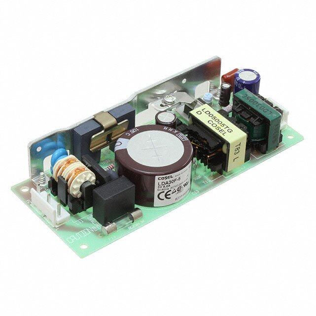
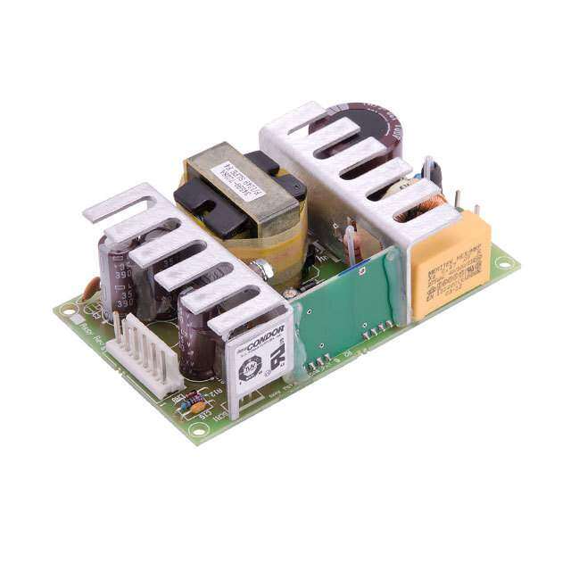
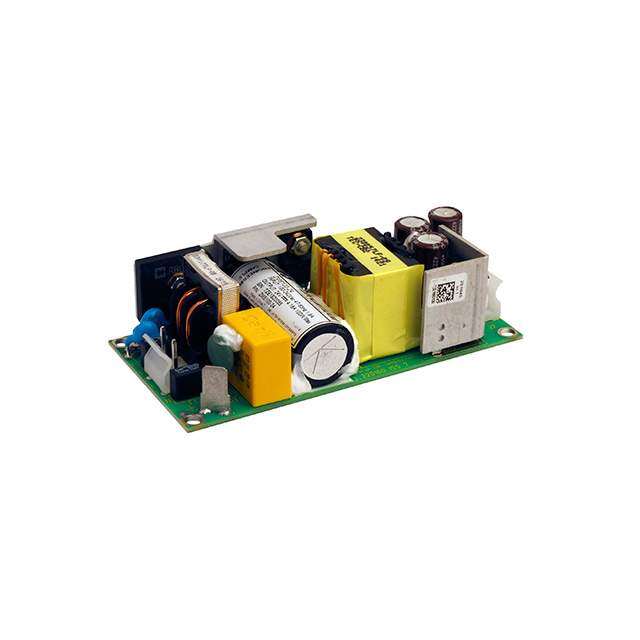
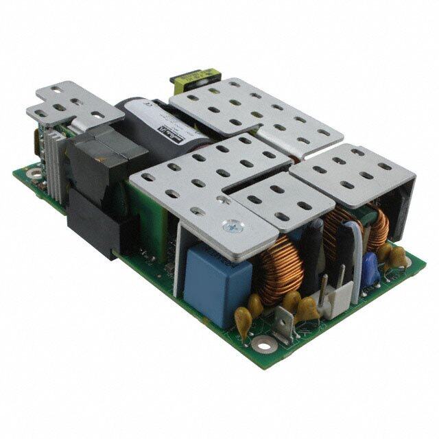
ICGOO电子元器件商城为您提供ECL25US12-S由XP POWER设计生产,在icgoo商城现货销售,并且可以通过原厂、代理商等渠道进行代购。 ECL25US12-S价格参考。XP POWERECL25US12-S封装/规格:AC DC 转换器, 封闭式 AC DC 转换器 1 输出 12V 2.1A 85 ~ 264 VAC 输入。您可以下载ECL25US12-S参考资料、Datasheet数据手册功能说明书,资料中有ECL25US12-S 详细功能的应用电路图电压和使用方法及教程。
| 参数 | 数值 |
| 3D型号 | http://www.xppower.com/cad/ECL25_IGES.zip |
| 产品目录 | |
| 描述 | AC/DC CONVERTER 12V 25W |
| 产品分类 | |
| 品牌 | XP Power |
| 数据手册 | |
| 产品图片 |
|
| 产品型号 | ECL25US12-S |
| rohs | 无铅 / 符合限制有害物质指令(RoHS)规范要求 |
| RoHS指令信息 | |
| 产品系列 | ECL |
| 其它名称 | 1470-1193 |
| 其它有关文件 | |
| 功率(W) | 25W |
| 功率(W)-最大值 | 25W |
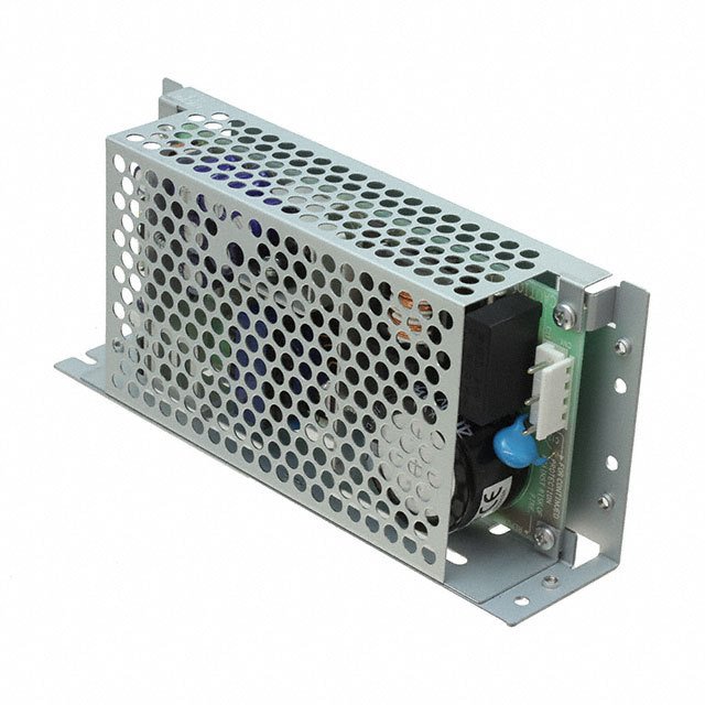
| 大小/尺寸 | 3.78" 长 x 1.57" 宽 x 1.12" 高 (96.0mm x 40.0mm x 28.5mm) |
| 安装类型 | 底座安装 |
| 工作温度 | -20°C ~ 70°C |
| 应用 | ITE(商业) |
| 所需最小负载 | 无 |
| 效率 | 80% |
| 标准包装 | 1 |
| 特性 | 可调输出,DC 输入能力,通用输入 |
| 电压-输入 | 85 ~ 264 VAC |
| 电压-输出1 | 12V |
| 电压-输出2 | - |
| 电压-输出3 | - |
| 电压-输出4 | - |
| 电压-隔离 | 3kV(3000V) |
| 电流-输出(最大值) | 2.1A |
| 类型 | 封闭式 |
| 认可 | - |
| 输出数 | 1 |


PDF Datasheet 数据手册内容提取
C 5-30 Watts xppower.com D ECL Series - C A • Ultra Compact Size • Single, Dual & Triple Outputs • Open Frame PCB & Chassis Mount • Encapsulated PCB Mount Versions • <0.3 W No Load Input Power • Peak Load Capability • 3 Year Warranty Specification Input General Input Voltage • 85-264 VAC (120-370 VDC) Efficiency • See tables Input Frequency • 47-63 Hz Isolation • 3000 VAC Input to Output Input Current • ECL05: 0.1 A rms, ECL10: 0.2 A rms Switching Frequency • 70 kHz typical ECL15: 0.3 A rms, ECL25: 0.4 A rms Power Density • ECL05: 2.25 W/In3 (PCB Mount version) ECL30: 0.8 A rms at 230 VAC ECL10: 5.50 W/In3 (PCB Mount version) Inrush Current • 20 A at 115 VAC, 40 A at 230 VAC, ECL15: 5.30 W/In3 (PCB Mount version) cold start at 25 °C ECL25: 5.90 W/In3 (PCB Mount version) Earth Leakage Current • Class II construction no earth ECL30: 7.10 W/In3 (PCB Mount version) Power Factor • EN61000-3-2, class A MTBF • ECL05/10: >450 kHrs, No Load Input Power • <0.3 W ECL15/25/30: >400 kHrs, Input Protection • ECL05/10: Internal T1 A/250 VAC fuse to MIL-HDBK-217Fat 25 °C, GB ECL15/25/30: Internal T2 A/250 VAC fuse Environmental Output Operating Temperature • -20 °C to +70 °C, derate linearly from Output Voltage • See tables 100% at +50 °C to 50% at +70 °C Output Voltage Trim • ±5% on output 1 only, on multiple output versions, V2 & V3 will track by same Cooling • Convection-cooled percentage, (not ‘-E’ or ‘-S’ versions) Operating Humidity • 95% RH, non-condensing Initial Set Accuracy • ±1% for output 1, Storage Temperature • -40 °C to +85 °C ±1% for output 2 of UD01 & UD02 versions, Operating Altitude • 3000 m ±5% for output 2 & output 3 of other versions Vibration • 2 g, 10 Hz to 500 Hz, 10 mins/cycle, Minimum Load • Single output versions: none, 60 mins each cycle Multi output versions: UD01 & UD02: 10% V1 & V2 EMC & Safety UD03: 10% V1, 20% V2 UT02 & UT03: 10% V1, 20% V2 & V3 Emissions • EN55032, level B conducted & radiated to meet regulation specifications Harmonic Currents • EN61000-3-2, class A Start Up Delay • 3 s max Voltage Flicker • EN61000-3-3 Start Up Rise Time • 14 ms max Hold Up Time • 16 ms typical for single output versions, ESD Immunity • EN61000-4-2, level 3 Perf Criteria A 12 ms typical for multiple output versions, Radiated Immunity • EN61000-4-3, 10 V/m 80% mod at full load & 115 VAC Perf Criteria A Line Regulation • ±0.5% max for single output versions and EFT/Burst • EN61000-4-4, level 3, Perf Criteria A output 1 of multiple output versions, Surge • EN61000-4-5, installation class 3, ±0.9% max for output 2 & output 3 of Perf Criteria A multiple output versions Conducted Immunity • EN61000-4-6, 10 Vrms Perf Criteria A Load Regulation • 1% max for single output versions, for multiple output versions (see note 5) Magnetic Fields • EN61000-4-8, 10 A/m, Perf Criteria A Cross Regulation • Multi output versionsonly (see note 5) Dips & Interruptions • EN61000-4-11, 30% for 10 ms, Transient Response • 4% max deviation, recovery to within 60% for 100 ms, 100% for 5000 ms 1% in 500 µs for a 25% load change Perf Criteria A, B, B Ripple & Noise • Single output versions: Safety Approvals • IEC60950-1:2005 Ed 2 / IEC62368-1:2014 3.3-5 V versions: 50 mV pk-pk, UL 62368-1 & CAN/CSA C22.2 No. 62368- 12-15 V versions: 120 mV pk-pk, 1-14, EN62368-1:2014/A11:2017 24-48 V versions: 200 mV pk-pk, Multiple output versions: 1% pk-pk on any output, 20 MHz bandwidth Overvoltage Protection • 115-140% Vnom, 195-216% Vnom ECL05/10/15/25 with 3.3 V Overload Protection • Single output versions: ECL05/10/15: 120-150%, ECL25: 120-170% of total power Multiple output versions: 140-200% of total power Short Circuit Protection • Trip and restart (hiccup mode) Temperature • 0.05%/°C Coefficient
A ECL05/10 Models and Ratings C Output Current Output Power Output Voltage Efficiency Model Number(2) - Nominal Peak(1) D 4.3 W 3.3 VDC 1.30 A 1.69 A 72% ECL05US03 5.0 W 5.0 VDC 1.00 A 1.30 A 75% ECL05US05 C 5.0 W 9.0 VDC 0.55 A 0.71 A 78% ECL05US09 5.0 W 12.0 VDC 0.41 A 0.54 A 78% ECL05US12 5.0 W 15.0 VDC 0.33 A 0.44 A 80% ECL05US15 5.0 W 24.0 VDC 0.21 A 0.27 A 82% ECL05US24 5.0 W 48.0 VDC 0.10 A 0.13 A 82% ECL05US48 8.6 W 3.3 VDC 2.60 A 3.38 A 72% ECL10US03 10.0 W 5.0 VDC 2.00 A 2.60 A 75% ECL10US05 10.0 W 9.0 VDC 1.10 A 1.43 A 78% ECL10US09 10.0 W 12.0 VDC 0.83 A 1.08 A 78% ECL10US12 10.0 W 15.0 VDC 0.67 A 0.87 A 80% ECL10US15 10.0 W 24.0 VDC 0.42 A 0.55 A 82% ECL10US24 10.0 W 48.0 VDC 0.21 A 0.27 A 82% ECL10US48 Notes 1. Peak load lasting <30 s with a maximum duty cycle of 10%, average output power not to exceed nominal. 2. Add suffix to model number to define typeO: ad d ‘-P ’ for PCB (m-Po)unt, add ‘-T’ for chassis mount, add ‘-E’ for encapsulated. Mechanical Details Open Frame - PCB Mount (-P) Encapsulated (-E) (-E) (-P) (-P) 0.80 1.95 (20.3) (49.5) ACN +Vo 0.91 (23.0) (12.50.04) 0(1..09715) (-E) (-E) -Vo ACL 0.40 (10.1) V Adj. 4 x ø 0.04 (ø1.0) 0.075 1.80 0.10 0(1.91) (45.7) (2.5) 0.39 (10.0) 0.90 1.07 (27.2) (22.9) 0.80 ±0.01 (20.32 ±0.3) 0.17 0.13 (3.4) (4.4) 0.73 0 0.15 (18.5) (3.8) ACL ACN Open Frame - Chassis Mo un tøø (00..-0074T ((øø)11 ..80)) (-T) (522.0.46) 1.80 ±0.01 (45.72 ±0.3) TO P VIEW T T -Vo +Vo 2.56 (65.0) 4-ø0.1V2 6 (ø3.20) (30..4103) 0.40 ±0.01 (10.16 ±0.3) 1.00 0.68 ACN +-VVoo (25.4) (17.4) ACL 0.15 0.14 2.28 (58.0) V Adj. (4.0) (3.5) 0.73 (18.5) 0.85 (21.6) Notes 1. All dimensions in inches (mm). Mating Connectors(-T version only) 2. Weight: ECL05/10 P Version: 0.057 lbs (26 g) Input Connector: JST PHR-3 ECL05/10 T Version: 0.057 lbs (26 g) Output Connector: JST PHR-2 ECL05/10 E Version: 0.13 lbs (60 g) Crimps: SPH-002T-P0.5S 3. Tolerances: x.xx = ± 0.02 (x.x = ± 0.5) Cable harness with 300 mm wire available, order part no. ECL10 LOOM KIT x.xxx = ± 0.01 (x.xx = ± 0.25)
C ECL15 Models and Ratings D Output Output Output Current - Efficiency Model Number(2,3) Power Voltage Nominal Peak(1) C 10 W 3.3 VDC 3.00 A 3.90 A 75% ECL15US03 A 15 W 5.0 VDC 3.00 A 3.90 A 78% ECL15US05 15 W 9.0 VDC 1.67 A 2.17 A 80% ECL15US09 15 W 12.0 VDC 1.25 A 1.62 A 80% ECL15US12 15 W 15.0 VDC 1.00 A 1.30 A 80% ECL15US15 15 W 24.0 VDC 0.63 A 0.82 A 82% ECL15US24 15 W 48.0 VDC 0.32 A 0.41 A 82% ECL15US48 Notes 1. Peak load lasting <30 s with a maximum duty cycle of 10%, average output power not to exceed nominal. 2. Add suffix to model number to define type: add ‘-P’ for PCB mount, add ‘-T’ for chassis mount, add ‘-E’ for encapsulated, add ‘-S’ for screw terminals. 3. A screw terminal version (-S) is available with DIN clip attached, add suffix ‘D’, e.g. ECL15US24-SD, DIN rail mounting kit is available as a separate item, order code ECL15 DIN CLIP. 4. For medically-approved 15 W power supplies contact sales or see www.xppower.com for details of CU15-M series and VCP15 series. Mechanical Details Open Frame - PCB Mount (-P) Encapsulated (-E) 0.50 (12.6) 2.44 (62.0) -Vo ACN 0.11 ACN -Vo 0.79 (13.33.13) TOP VIEW (2.9) (20.1) 1.21 (30.7) 0.69 +Vo +Vo (17.5) ACL 0.79 ACL V Adj. (20.1) 0.69 2.13 0.21 0.15 2.13 (17.5) (54.1) (5.4) E (-E) (-P) 0(1.0.66) (3.9) (54.1) 0(9.3.16) (26.55.60) 0.17 (4.4) 0.96 0.15 0.78 (24.4) (3.8) (20.0) max 4x ø 0.04 (ø1.0) ø 0.07 (ø1.8) ø 0.04 (ø1.0) 0.39 (10.0) Open Frame - Chassis Mount (-T) Screw Terminal (-S) 3.10 (78.7) 2.95 (75.0) 4x ø 0.14 4-0.12 (3.2) (4x ø 3.5) 1.36 1.25 0.95 ACN -Vo (34.5) ACN TOP VIEW -Vo (31.7) (24.1) ACL +Vo 1.00 ACL +Vo (25.4) 0.44 (11.1) 0.15 0.15 2.80 (71.1) V Adj. 0.39 2.54 (3.8) (3.8) (10.0) (64.5) (-S) 1º 0.78 0.91 (20.0) max (23.1) 1.04 (26.4) 0.27 0.09 3.30 (84.0) (6.8) (2.5) Optional DIN clip Notes 1. All dimensions in inches (mm). Mating Connectors (-T version only) 2. Weight: ECL15 P Version: 0.07 lbs (35 g) Input Connector: JST PHR-3 T Version: 0.07 lbs (35 g) Output Connector: JST PHR-4 E Version: 0.20 lbs (90 g) Crimps: SPH-002T-P0.5S S Version: 0.24 lbs (110 g) Cable harness with 300 mm wire available, order part no. ECL15 LOOM KIT 3. Tolerances: x.xx = ± 0.02 (x.x = ± 0.5) x.xxx = ± 0.01 (x.xx = ± 0.25)
A ECL15UD/UT Models and Ratings C Output 1 Output 2 Output 3 Model Output Power Efficiency - Voltage Current(2) Voltage Current(2) Voltage Current(2) Number(3,4) D 15 W +12.0 V 0.65 A -12.0 V 0.650 A 82% ECL15UD01 15 W +15.0 V 0.50 A -15.0 V 0.500 A 82% ECL15UD02 C 15 W 5.0 V(1) 1.50 A 12.0 V(1) 0.625 A 81% ECL15UD03 15 W 5.0 V(1) 2.00 A +12.0 V 0.200 A -12.0 V 0.200 A 81% ECL15UT02 15 W 5.0 V(1) 2.00 A +15.0 V 0.150 A -15.0 V 0.150 A 81% ECL15UT03 Notes 1. Isolated output 5. UD01/UD02:Load regulation <3%, 10-100% load. 2. Peak load of 130% lasting <30 s with a maximum duty cycle of 10%, average Cross regulation <3%, one output fixed, the other varied from output power not to exceed nominal. 10-100% load 3. Add suffix to model number to define type: add ‘-P’ for PCB mount, add ‘-T’ UD03: Load regulation <1% V1, <10% V2 for chassis mount, add ‘-E’ for encapsulated, add ‘-S’ for screw terminals. Cross regulation <10% V2, V1 varied from 10-100% load 4. A screw terminal version (-S) is available with DIN clip attached, add suffix ‘D’ UT02/UT03: Load regulation <1% V1, <10% V2 & V3 e.g. ECL15UT02-SD, DIN rail mounting kit is available as a separate item, order Cross regulation <10% V2 & V3, V2 & V3 at 50% load & V1 code ECL15 DIN CLIP. varied from 20-100% load Mechanical Details Open Frame - PCB Mount (-P) 2.44 (62.0) Pin1 Pin UD01/02 UD03 UT02/03 1.20 (30.7) 0.06 (1.6) 0.1550.96 (17.5) (3.9AA)CCNL 2.13 (54.1) PinV5A d 0.07 (1.8)j PPPiii nnn 2340.29 (7.4) 0.25 (6.3) 0.25 (6.3) 0.29 (7.4) 0.15 (3.8) 0.17 (4.4) 7 77 --øø00..0047 ((øø11..08)) 0.79 (20.0) max NP12345 = No pCiNNVVnO21PP.M VV21NVV RR21PTTNN VC1VVV OR321MTN Open Frame - Chassis Mount (-T) A 4-ø0.13 (ø3.20) Pin UD01/02 UD03 UT02/03 AAACNCNPL PPPPPiiiiinnnnn54321 0.15 (3.8) 0.95 (24.1) 1.25 (31.8) 0.79 (20.0)Max 0.91 (23.1) 12345 CCCVVOOO21MMM VV21NVV RRC21TTNN VC1VVV OR321MTN 0.15 (3.081) VAdj NC = No connection. 2.80 (71.1) 3.10 (78.7) Encapsulated (-E) 2.56 ( 65.0) 0.25 ( 6.3) 0.54 (13.7) Pin UD01/02 UD03 UT02/03 0.69 (17.5) 0.12 (3.1)0 AAACCNL TTo2p V iew PPPPPiiiiinnnnn14235 0.25 (6.3) 1.31 (33.5) 0.39 (10.0) 0.96 (24.4) 12345 CNNVVO21PPM VV21NVV RR21PTTNN VC1VVV OR321MTN 0.5 4 ( 13.7 ) 4-ø0.04 ( ø1.0) NP = No pin. C1 2.13 (54.1) Screw Terminal (-S) 0.2 1 ( 5.4) 4 0.18 (4.6) 2-ø0.14 (ø3.5) 1.03 (26.3) 0.39 (10.0) Pin1 Pin UD01/02 UD03 UT02/03 AAA2CC NL Top View PPPPiiiinnnn5432 1.18 (30.0) 1.36 (34.5) 1.04 (26.4) 123 CCVOO2MM V2NV RC2TN CVVO32M 0.44 (11.2) 0.18 (4.5) 22..5965 ((6755..10)) 0.10 (2.5) P0.10 (2 .5) 0.10 (2.5) ODIpN ti oc0nli.pa2 l7 (6 .8) NC45 = No cCoVOn1Mnection.V1+ VR1TN V1V R1TN 3.31 (84.0) Notes 1. All dimensions in inches (mm). 3. Weight: ECL15 UD/UT: P Version: 0.09 lbs (40 g) Mating Connectors (-T version only) 2. Tolerances: x.xx = ± 0.02 (x.x = ± 0.5) T Version: 0.09 lbs (40 g) Input Connector: JST PHR-3 x.xxx = ± 0.01 (x.xx = ± 0.25) E Version: 0.21 lbs(95 g) Output Connector: JST XHP-5 S Version: 0.26 lbs (120 g)
C ECL25 Models and Ratings D Output Output Output Current - Efficiency Model Number(2,3) Power Voltage Nominal Peak(1) C 20 W 3.3 VDC 6.00 A 7.80 A 75% ECL25US03 A 25 W 5.0 VDC 5.00 A 6.50 A 78% ECL25US05 25 W 9.0 VDC 2.80 A 3.64 A 80% ECL25US09 25 W 12.0 VDC 2.10 A 2.73 A 80% ECL25US12 25 W 15.0 VDC 1.67 A 2.17 A 80% ECL25US15 25 W 24.0 VDC 1.04 A 1.35 A 82% ECL25US24 25 W 48.0 VDC 0.52 A 0.68 A 82% ECL25US48 Notes 1. Peak load lasting <30 s with a maximum duty cycle of 10%, average output 3. A screw terminal version (-S) is available with DIN clip attached, add suffix ‘D’, power not to exceed nominal. e.g. ECL25US24-SD, DIN rail mounting kit is available as a separate item, order 2. Add suffix to model number to define type: add ‘-P’ for PCB mount, add ‘-T’ code ECL25/30 DIN CLIP. for chassis mount, add ‘-E’ for encapsulated, add ‘-S’ for screw terminals. Mechanical Details Open Frame - PCB Mount (- P) (-P) EncapsulatedE (-E) (-E) (-P) E (-E) 3.10 2.96 (78.7) (75.2) 0.125 (3.2) ACN ACN 0.59 (15.0) 1.36 1.18 -Vo 1.18 TOP VIEW 1.50 (34.6) (30.0) 0.59 (30.0)0.16 -Vo (38.1) ACL +Vo (15.0) (4.1) ACL +Vo V Adj. 0.09 0(1.0.45) (72.28.54) 0(2.0.39) (27.28.54) (2.3) 0.8 8 (22.3) MAX 0.17 1 (4.4) 1.10 0 (27.9) 0.15 (3.8) 4x ø 0.039 (ø1.0) ø0.04 (ø1.0) 0.39 (10.0) ø0.07 (ø 1.8) Open Frame - Chassis Mount (-T) Screw Terminal (-S) (-S) (-S) 3.46 (87.9) 4- 0.15 (3.81) 3.43 (87.0) 4(4xx øø03..154) 0.44 (11.2) (314.3.66) (217.1.09) AACCNL +-VVoo AACCNL TOP VIEW -Vo(201.8.34)1.20 1.57 +Vo (30.5) (40.0) V Adj. 0(3..133) 0(3..133) 3.20 (81.3) (736.0.41) 0.39 (10.0) 1º 0.88 1.00 (22.4) MAX (25.4) 1.12 (28.5) 3.78 (96.0) 0.27 0.10 (6.8) (2.5) Optional DIN clip Notes 1. All dimensions in inches (mm). Mating Connectors (-T version only) 2. Weight: ECL25: P Version: 0.14 lbs (66 g) Input Connector: JST XHP-3 T Version: 0.14 lbs (66 g) Output Connector: JST XHP-6 E Version: 0.33 lbs (150 g) Crimps: SXH-002T-P0.6 S Version: 0.37 lbs (170 g) Cable harness with 300 mm wire available, order part no. ECL25 LOOM KIT 3. Tolerances: x.xx = ± 0.02 (x.x = ± 0.5) x.xxx = ± 0.01 (x.xx = ± 0.25)
A ECL30UD/UT Models and Ratings C Output 1 Output 2 Output 3 Model Output Power Efficiency - Voltage Current(2) Voltage Current(2) Voltage Current(2) Number(3,4) D 30 W +12.0 V 1.3 A -12.0 V 1.30 A 84% ECL30UD01 30 W +15.0 V 1.0 A -15.0 V 1.00 A 83% ECL30UD02 C 30 W 5.0 V(1) 3.0 A 12.0 V(1) 1.30 A 81% ECL30UD03 30 W 5.0 V(1) 3.0 A +12.0 V 0.63 A -12.0 V 0.63 A 83% ECL30UT02 30 W 5.0 V(1) 3.0 A +15.0 V 0.50 A -15.0 V 0.50 A 81% ECL30UT03 Notes 1. Isolated output 5. UD01/UD02: Load regulation <3%, 10-100% load. 2. Peak load of 130% lasting <30 s with a maximum duty cycle of 10%, average Cross regulation <3%, one output fixed, the other varied from output power not to exceed nominal. 10-100% load 3. Add suffix to model number to define type: add ‘-P’ for PCB mount, add ‘-T’ UD03: Load regulation <1% V1, <10% V2 for chassis mount, add ‘-E’ for encapsulated, add ‘-S’ for screw terminals. Cross regulation <10% V2, V1 varied from 10-100% load 4. A screw terminal version (-S) is available with DIN clip attached, add suffix ‘D’ UT02/UT03: Load regulation <1% V1, <10% V2 & V3 e.g. ECL30UT02-SD, DIN rail mounting kit is available as a separate item, order Cross regulation <10% V2 & V3, V2 & V3 at 50% load & V1 code ECL25/30 DIN CLIP. varied from 20-100% load Mechanical Details Open Frame - PCB Mount (-P) 2 2.96 (75.2) Vadj Pin UD01/02 UD03 UT02/03 Pin1 1.36 (34.6) 1 1.18 (29.9) 0.09 (2.3)AACCLN 0 . 05 (1.4) 2 .85 (72.4) PPPPiiinninn23 450.09 (2.3) 0.29 (7.5) 0.29 (7.5) 0.29 (7.5) 0.29 (7.5) 0.15 (3.8) 0.17 (4.4) øø 0 0..0047 ((øø11..80)) 0.88 (22.3) Max 1.05 (26.7) NP12345 = No CpNNVVOin21PPM. VV12NVV RR12PTTNN C+-VVOVV321M1 Open Frame - Chass is Mount (-T) 33..2406 ((8817..39 )) Pin UD01/02 UD03 UT02/03 0.13 (3.3) Vadj 4-ø0.15 (ø3.8 ) 1 V2 V1 RTN -V1 ANACCPNL PPPPPiiiiinnnnn21543P 0.13 (3.3) 1.10 (27.9) 1.36 (34.6) 0.88 (22.4) Max 1.00 (25.4) 2345 CCCVOOO1MMM V2NVV RC12TN C+VVOV32M1 0.12 (3.0) NC = No connection. Encapsulated (-E) 0.29 (7.5) 0.59 (14.9) Pin UD01/02 UD03 UT02/03 1.18 (29.9) 0.16 (4.1) AACCNL Top Vi ew PPPPPP0iiiiinnnnn32541 0.29 (7.5) 0.59 (14.9) 1.50 (38.1) 0.39 (10.0) 1.10 (28.0) 12345 CNNVVO21PPM VV12NVV RR12PTTNN C+-VVOVV321M1 0.12 (3 .2) 2.85 (7 2.4) C0.0 4 (1.0) 7-ø0.04 (ø1. 00) NP = No pin. 3.10 (78.7) Screw Terminal (-S ) 0.19 (4.8) 2-ø0.14(ø3.5) 0.39 (10.0) Pin UD01/02 UD03 UT02/03 0 Pin1 1 V2 V1 RTN -V1 00.44 (11.2).1 8AA (4CC .LN5) TTo33..40p33 ((87V77..i00e ))w 0.10 (4 .5) 0.10 (4.5)PPPPiiiinnnn2345 1.21 (30.7) 1.39 (35.2) 1.57 (40.0) 0(2..1 50) Optional DIN cli p 0(6 . .28 7)1.12 (28.5) N C2345 = No CCCcVOOOo1nMMMnectioVn2.NVV RC12TN C+VVOV32M1 3.78 (96.0) No tes 1. All dimensions in inches (m m ). 3. Weight: ECL30 UD/UT: P Version: 0.13 lbs (60 g) Mating Connectors (-T version only) 2. Tolerances: x.xx = ± 0.02 (x .x = ± 0.5) T Version: 0.13 lbs (60 g) Input Connector: JST XHP-3 x.xxx = ± 0.01 (x.xx = ± 0.25) E Version: 0.34 lbs (155 g) Output Connector: JST XHP-5 S Version: 0.39 lbs (175 g) 18 Feb 20