ICGOO在线商城 > ECC-T3F330JG2
- 型号: ECC-T3F330JG2
- 制造商: Panasonic Corporation
- 库位|库存: xxxx|xxxx
- 要求:
| 数量阶梯 | 香港交货 | 国内含税 |
| +xxxx | $xxxx | ¥xxxx |
查看当月历史价格
查看今年历史价格
ECC-T3F330JG2产品简介:
ICGOO电子元器件商城为您提供ECC-T3F330JG2由Panasonic Corporation设计生产,在icgoo商城现货销售,并且可以通过原厂、代理商等渠道进行代购。 提供ECC-T3F330JG2价格参考以及Panasonic CorporationECC-T3F330JG2封装/规格参数等产品信息。 你可以下载ECC-T3F330JG2参考资料、Datasheet数据手册功能说明书, 资料中有ECC-T3F330JG2详细功能的应用电路图电压和使用方法及教程。
| 参数 | 数值 |
| 产品目录 | |
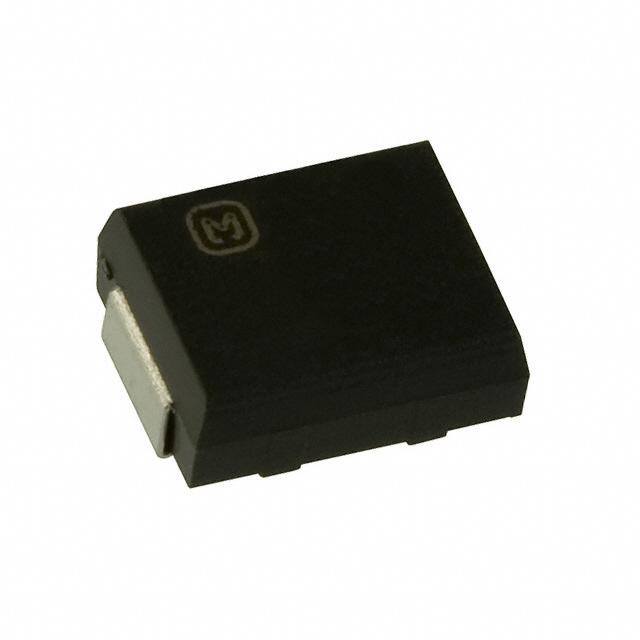
| 描述 | CAP CER 33PF 3KV 5% SL SMD |
| 产品分类 | |
| 品牌 | Panasonic Electronic Components |
| 数据手册 | |
| 产品图片 |
|
| 产品型号 | ECC-T3F330JG2 |
| rohs | 无铅 / 符合限制有害物质指令(RoHS)规范要求 |
| 产品系列 | - |
| 产品目录绘图 |
|
| 产品目录页面 | |
| 其它名称 | PCC2374DKR |
| 包装 | Digi-Reel® |
| 厚度(最大值) | 0.091"(2.30mm) |
| 大小/尺寸 | 0.224" 长 x 0.177" 宽(5.70mm x 4.50mm) |
| 安装类型 | 表面贴装,MLCC |
| 容差 | ±5% |
| 封装/外壳 | 非标准型 SMD |
| 工作温度 | -25°C ~ 105°C |
| 应用 | 通用 |
| 引线形式 | - |
| 引线间距 | - |
| 标准包装 | 1 |
| 温度系数 | SL/GP |
| 特性 | 高电压 |
| 电压-额定 | 3000V(3kV) |
| 电容 | 33pF |
| 等级 | - |
| 高度-安装(最大值) | - |



- 商务部:美国ITC正式对集成电路等产品启动337调查
- 曝三星4nm工艺存在良率问题 高通将骁龙8 Gen1或转产台积电
- 太阳诱电将投资9.5亿元在常州建新厂生产MLCC 预计2023年完工
- 英特尔发布欧洲新工厂建设计划 深化IDM 2.0 战略
- 台积电先进制程称霸业界 有大客户加持明年业绩稳了
- 达到5530亿美元!SIA预计今年全球半导体销售额将创下新高
- 英特尔拟将自动驾驶子公司Mobileye上市 估值或超500亿美元
- 三星加码芯片和SET,合并消费电子和移动部门,撤换高东真等 CEO
- 三星电子宣布重大人事变动 还合并消费电子和移动部门
- 海关总署:前11个月进口集成电路产品价值2.52万亿元 增长14.8%


PDF Datasheet 数据手册内容提取
High Voltage Ceramic Capacitors (SMD) High Voltage Ceramic Capacitors For Surface Mounting 1 to 5 kVDC ■ ■ Features Recommended Application ● Resin molded SMD type for reflo w solderings ● Ballast circuit of LCD backlighting inverter ● High reliability through use of disc capacitor element (For 3 to 5 kVDC Char.SL/GP) ● Wide rated voltage ranges from 1 kV to 5 kV, through a ● Snubber circuit of switching power supply disc element which withstand high voltage and outcurve (For 1 to 2 kVDC Char.B/Y5P) terminals ● Wide rated voltage range 1 to 5 kV ■ Explanation of Part Numbers 1 2 3 4 5 6 7 8 9 10 11 12 E C C T 3 F 4 7 0 J G ProductCode PackagingStyle RatedVoltage NominalCapacitance Cap.Tolerance Temp.Char. Suffix Code Class Code Style CodeRatedVoltage Ex. Capacitance Code Tol. CodeTemp.Char. Code Stylecode ECC Class1 T Tapedtype 3A 1kVDC 100 10pF D ±0.5pF G SL/GP Nil 1 ECK Class2 3D 2kVDC 470 47pF J ±5% B B/Y5P M 2 3F 3kVDC 101 100pF K ±10% 2 3 3G 4kVDC 221 220pF M ±20% Y 4 3H 5kVDC ■ ■ Construction Dimensions in mm (not to scale) ● Inside Terminal ● style 1, 3 H Electrode MoldedResin S S E L W CeramicElement Terminal A B ● Outside Terminal ● style 2, 4 ThisFigureappliedto L StyleCode2,4(Adddim.L1) Electrode MoldedResin L1 Symbol L1 L W H S E A B Style 1 — 7.1±0.56.3±0.32.5±0.31.45±0.302.5±0.2 (2.0) (3.7) CeramicElement Terminal Dim Style 2 10.8±0.56.8±0.56.3±0.32.5±0.3 — 2.5±0.2 (2.0) (3.7) (mm) Style 3 — 5.7±0.54.5±0.32.3max.0.85±0.302.5±0.2 (1.7) (3.1) Style 4 9.4±0.3 5.5±0.54.5±0.32.3±0.2 — 2.5±0.2 (1.7) (3.1) Design and specifi cations are each subject to change without notice. Ask factory for the current technical specific ations before purchase and/or use. Should a safety concern arise regarding this product, please be sure to contact us immediately. Dec. 2007
High Voltage Ceramic Capacitors (SMD) ■ Specific ations Characteristics Char. SL/GP Char. B/Y5P Operating Temperature Range –25 to 105 °C Rated Voltage 2 to 3 kVDC 4 to 5 kVDC 5 kVDC 1 to 2 kVDC Dielectric 200 % of Rated Voltage150 % of Rated Voltage120 % of Rated Voltage200 % of Rated Voltage Withstanding Voltage for 1 to 5 seconds for 1 to 5 seconds for 1 to 5 seconds for 1 to 5 seconds Capacitance Within the specifie d tolerance, when measured Within the specifie d tolerance, when measured at 1 MHz±20 %, 1 to 5 Vrms. and 20 °C at 1 kHz±20 %, 1 to 5 Vrms. and 20 °C Q or Dissipation Factor 30 pF or under Q > 400+20 C (C:Cap.pF) tan δ < 0.025 (tan δ) over 30 pF Q > 1000 at 1 kHz±20 %,1 to 5 Vrms. and 20 °C at 1 MHz±20 %,1 to 5 Vrms. and 20 °C Insulation Resistance 10000 M (cid:1) min. at 500 VDC and 1 minute electrifi cation Temperature Temperature Coeffic ient: Max. Cap. Change:±10 % Characteristics +350 to –1000 ppm/ °C (Temperature Range : –25 to 85 °C) (Temperature Range : 20 to 85 °C) ■ Packaging Methods (Taping) ● Minimum Quantity/Packing Unit Minimum Packing Packing Quantity Carton Dimensions Type Packaging Style Part Number Quantity in Carton in mm L(cid:2)W(cid:2)H 1 to 5 kVDC Embossed Carrier 2000 EC(cid:1)T3(cid:1)(cid:1)(cid:1)(cid:1)(cid:1)(cid:1) 5 to 470 pF 6000 pcs. 350(cid:2)350(cid:2)62 (style 1) Taping pcs./reel 5 kVDC Embossed Carrier 2000 ECCT3H(cid:1)(cid:1)(cid:1)(cid:1)(cid:1)M 5 to 27 pF 4000 pcs. 350(cid:2)350(cid:2)62 (style 2) Taping pcs./reel 4 kVDC Embossed Carrier 3000 ECCT3G(cid:1)(cid:1)(cid:1)JG2 10 to 27 pF 9000 pcs. 350(cid:2)350(cid:2)62 (style 3) Taping pcs./reel 5 kVDC Embossed Carrier 3000 ECCT3H(cid:1)(cid:1)(cid:1)(cid:1)(cid:1)Y 5 to 15 pF 6000 pcs. 350(cid:2)350(cid:2)62 (style 4) Taping pcs./reel ● Reel ● Embossed Carrier Taping style 1, 3, 4 (W=12mm) Feedinghole Chippocket E t1 φD0 P2 P0 C E A B FW B r D t2 Chipcomponent P1 Taperunning direction style 2 Feedinghole Chippocket A W t t1 φD0 P2 P0 E A F W B t2 Chipcomponent P1 Taperunning direction Unit:(mm) Unit:(mm) Symbol A B C D E W t r Symbol A B W F E P1 P2 P0 φD0 t1 t2 (Dmimm.) stsytlyel e1 ,2 3 330±5 60 min.13.0±0.521.0±1.02.0±0.51235..55±±11..552.0±0.5 R1.0 style1 ±60.5.2 ±70.5.2 1±20..30 ±50.5.1 ±10.7.150 ±80.0.1 ±20.0.1 ±40.0.1 +–100..51 ±00.3.1 ±30.2.3 style 4 17.5±1.5 Dim. style2 ±60.6.2501±10..222±40..301±10..15±10.7.1501±20..10 ±20.0.1 ±40.0.1 +–100..51 ±00.3.1 ±30.2.3 (mm)style3 ±40.8.2 ±60.0.2 1±20..30 ±50.5.1 ±10.7.150 ±80.0.1 ±20.0.1 ±40.0.1 +–100..51 ±00.3.1 ±20.8.3 style4 ±40.7.2 1±00..501±60..30 ±70.5.1 ±10.7.150 ±80.0.1 ±20.0.1 ±40.0.1 +–100..51 ±00.3.1 ±20.8.350 Design and specifi cations are each subject to change without notice. Ask factory for the current technical specific ations before purchase and/or use. Should a safety concern arise regarding this product, please be sure to contact us immediately. Dec. 2007
High Voltage Ceramic Capacitors (SMD) ● Leader Part and Taped End Notloaded Chipcomponentposition Notloaded Leadertape 40mmmin. 20mmmin. 400mmmin. ■ Ratings and Characteristics ● Rated Voltage 1 to 5 kVDC Rated Voltage Part Number Capacitance (pF) Cap. Tolerance (%) Temp. Char Style ECCT3H050DGM 5 ±0.5 pF SL/GP ECCT3H100JGM 10 ±5 SL/GP ECCT3H120JGM 12 ±5 SL/GP ECCT3H150JGM 15 ±5 SL/GP Style 2 ECCT3H180JGM 18 ±5 SL/GP ECCT3H220JGM 22 ±5 SL/GP 5 kVDC ECCT3H270JGM 27 ±5 SL/GP ECCT3H050DGY 5 ±0.5 pF SL/GP ECCT3H080DGY 8 ±0.5 pF SL/GP ECCT3H100JGY 10 ±5 SL/GP Style 4 ECCT3H120JGY 12 ±5 SL/GP ECCT3H150JGY 15 ±5 SL/GP ECCT3G100DG2 10 ±0.5 pF SL/GP ECCT3G120JG2 12 ±5 SL/GP ECCT3G150JG2 15 ±5 SL/GP Style 3 ECCT3G180JG2 18 ±5 SL/GP 4 kVDC ECCT3G220JG2 22 ±5 SL/GP ECCT3G270JG2 27 ±5 SL/GP ECCT3G330JG 33 ±5 SL/GP ECCT3G390JG 39 ±5 SL/GP Style 1 ECCT3G470JG 47 ±5 SL/GP ECCT3F100DG2 10 ±0.5 pF SL/GP ECCT3F120JG2 12 ±5 SL/GP ECCT3F150JG2 15 ±5 SL/GP ECCT3F180JG2 18 ±5 SL/GP Style 3 ECCT3F220JG2 22 ±5 SL/GP 3 kVDC ECCT3F270JG2 27 ±5 SL/GP ECCT3F330JG2 33 ±5 SL/GP ECCT3F390JG 39 ±5 SL/GP ECCT3F470JG 47 ±5 SL/GP ECCT3F560JG 56 ±5 SL/GP ECCT3D680JG 68 ±5 SL/GP ECKT3D101KB 100 ±10 B/Y5P ECKT3D121KB 120 ±10 B/Y5P ECKT3D151KB 150 ±10 B/Y5P Style 1 2 kVDC ECKT3D181KB 180 ±10 B/Y5P ECKT3D221KB 220 ±10 B/Y5P ECKT3D271KB 270 ±10 B/Y5P ECKT3D331KB 330 ±10 B/Y5P ECKT3A391KB 390 ±10 B/Y5P 1 kVDC ECKT3A471KB 470 ±10 B/Y5P Notes ✽ This part number indicates taped type. ✽ Capacitance 9 pF or under is available by special order. Design and specifi cations are each subject to change without notice. Ask factory for the current technical specific ations before purchase and/or use. Should a safety concern arise regarding this product, please be sure to contact us immediately. Sep. 2006
High Voltage Ceramic Capacitors (SMD) ■ Typical Characteristics ● Temperature Characteristics Char. SL/GP Char. B/Y5P ( ) (Temp.Coeff.:+350 to –1000 ppm/°C) Temp.Range:–25 to 85 °C max.Cap.Change:±10 % %) %) e(+10 e( g g +10 n +5 n a a Ch 0 Ch ce –5 ce 0 n n cita –10 cita –10 pa –15 pa a a C C –20 0 20 40 60 80 100 120 –20 0 20 40 60 80 100 Temperature(˚C) Temperature(˚C) ● Characteristics of Voltage-Frequency Rated Voltage 3 kVDC Rated Voltage 4 kVDC Rated Voltage 5 kVDC 5000 5000 5000 3000 3000 3000 )p2000 )p2000 )p2000 Voltage(-Vp1507000000 123023pppFFF Voltage(-Vp1507000000 12340237ppppFFFF Voltage(-Vp1507000000 1202ppFF 47pF 300 300 300 200 200 200 10 20 30 50 70100 200 300 500 10 20 30 50 70100 200 300 500 10 20 30 50 70100 200 300 500 Frequency(kHZ) Frequency(kHZ) Frequency(kHZ) The graphs above show the maximum permissable voltage Permission self generation of heat temp era ture when using a capacitor with an AC sine wave voltage. vs. ambient temperature When measuring this voltage in room temperature (25 °C), the 25 capacitor self-heat generation will rise a maximum of 20 °C. n When using a pulse voltage or an AC voltage other than a sine eratioe(˚C)20 wave, confir m that the capacitor self-heat generation is less genatur15 than 20 °C in an ambient room temperature of 25 °C. elfper sm tAThhsee fs osure rtlfhfa-ech ees iatteut magtepionener arwatuhtireoenn a ttnhedem stpheeelrf -aahtmuerabeti eigsne tt nhreoero admtiifo ftener metenp mcepera ebtruaert teuw.reee ins ermissionofheatte150 P more than 25 °C, refer to the fi gure on the right. 0 20 40 60 80 100 120 ambienttemperature(˚C) ■ Application Examples ● LCD Backlighting Inverter ● Primary circuit and Snubber circuit of Switching Power Supply 3to5kV,10to47pF 1kV/2kV,100to470pF TypeBCorTypeFC1000to4700pF Lamp AC Input DC Output 2kV,100to330pF Design and specifi cations are each subject to change without notice. Ask factory for the current technical specific ations before purchase and/or use. Should a safety concern arise regarding this product, please be sure to contact us immediately. Feb. 2006
 Datasheet下载


