ICGOO在线商城 > EC11E1820402
 Datasheet下载
- 型号: EC11E1820402
- 制造商: ALPS
- 库位|库存: xxxx|xxxx
- 要求:
| 数量阶梯 | 香港交货 | 国内含税 |
| +xxxx | $xxxx | ¥xxxx |
查看当月历史价格
查看今年历史价格
EC11E1820402产品简介:
ICGOO电子元器件商城为您提供EC11E1820402由ALPS设计生产,在icgoo商城现货销售,并且可以通过原厂、代理商等渠道进行代购。 提供EC11E1820402价格参考¥8.54-¥37.66以及ALPSEC11E1820402封装/规格参数等产品信息。 你可以下载EC11E1820402参考资料、Datasheet数据手册功能说明书, 资料中有EC11E1820402详细功能的应用电路图电压和使用方法及教程。
| 参数 | 数值 |
| 品牌 | ALPS |
| 产品目录 | 无源元件 |
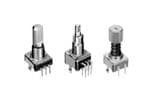
| 描述 | 编码器 11mm 18 RES 36 DTENT |
| 产品分类 | |
| 产品手册 | http://www.alps.com/products/WebObjects/catalog.woa/E/HTML/Encoder/Incremental/EC11/EC11E1820402.html |
| 产品图片 |
|
| rohs | 符合RoHS |
| 产品系列 | ALPS EC11E1820402 |
| mouser_ship_limit | 该产品可能需要其他文件才能进口到中国。 |
| 产品型号 | EC11E1820402 |
| 产品种类 | |
| 分辨率 | 18 PPR |
| 制动器数量 | 36 Detent |
| 商标 | ALPS |
| 封装 | Tray |
| 工厂包装数量 | 1200 |
| 带开关 | No Switch |
| 端接类型 | Through Hole |
| 输出 | Quadrature |


- 商务部:美国ITC正式对集成电路等产品启动337调查
- 曝三星4nm工艺存在良率问题 高通将骁龙8 Gen1或转产台积电
- 太阳诱电将投资9.5亿元在常州建新厂生产MLCC 预计2023年完工
- 英特尔发布欧洲新工厂建设计划 深化IDM 2.0 战略
- 台积电先进制程称霸业界 有大客户加持明年业绩稳了
- 达到5530亿美元!SIA预计今年全球半导体销售额将创下新高
- 英特尔拟将自动驾驶子公司Mobileye上市 估值或超500亿美元
- 三星加码芯片和SET,合并消费电子和移动部门,撤换高东真等 CEO
- 三星电子宣布重大人事变动 还合并消费电子和移动部门
- 海关总署:前11个月进口集成电路产品价值2.52万亿元 增长14.8%


PDF Datasheet 数据手册内容提取
11mm Size Metal Shaft Type EC11 Compact and highly reliable type available in many varieties ■Typical Specifications Items Specifications E Two phase of A, B n c Output signal Self-return switch o d (EC111 / EC11E0B) e rs Rating 10mA 5V DC 15,000 cycles Operating life 100,000 cycles( EC11K / EC11J) Operating temperature range −40℃ to +85℃ SM haftetal Product Line Structure Shaft Ltheen gsthha oftf Torque Number Number Push-on Travel of push- Operating life Minimum order uni (tpcs.) Product No. Drawing SIns configuration (mm) (mN・m) of detent of pulse switch on switch(mm) (cycles) Japan Export No. haftulate Without ー EC11B15202AN 1 d Horizontal 12±7 30 15 0.5 700 1,400 EC11B15242AZ 2 With 1.5 EC11B15242B1 3 SH haftollow 18 9 EC11E09204A4 30 15 Without ー EC11E15204A3 4 10±7 36 18 EC11E1820402 TypeRing 18 9 EC11E09244BS 30 EC11E15244G1 Flat 20 15 7+− 34 Without 0.5 EC11E153440D Vertical 10±7 36 15,000 1,200 2,400 EC11E18244AU 18 7+− 34 Without EC11E183440C With 5 18 9 EC11E09244AQ 10±7 30 EC11E15244B2 15 7+− 34 Without 1.5 EC11E1534408 10±7 36 EC11E18244A5 18 7+− 34 Without EC11E1834403 12±7 30 Without ー EC11G1560414 6 Less shaft wobble Serrated 25 8.5±5 Without 15 EC11G1574402 7 With 1.5 12±7 30 EC11G1564411 8 18 9 EC11K0920404 Without ー 9 30 15 1,000 2,000 EC11K1520406 18 9 EC11K0924404 Vertical Flat 20 12±5 0.5 100,000 30 15 EC11K1524406 10 With 18 9 EC11K0925416 1.5 30 15 EC11K1525413 Note Other varieties are also available. Please inquire. Refer to P.282 for product specifications. Refer to P.283 for attached parts. Refer to P.285 for product varieties. Refer to P.315 for soldering conditions. 276
EC11/11mm Size Metal Shaft Type Product Line Structure confSighuarfat tion Length (omf mth)e shaft (TmoNrq・ume) oNf udmetbeenrt oNfu pmublseer Psuwsihtc-ohn Trsawveitl cohf( pumsmh-)on O(pecryactilnegs )life MiJniampuamn order uEnxitp( oprcts.) Product No. DraNwoi.ng E 18 9 EC11J0920404 nc Without ー 11 o d 30 15 EC11J152040F ers 12±5 18 9 EC11J0924411 (Initial) Reflow Flat 20 0.5 100,000 600 600 10±4 (After reflow) 30 15 EC11J1524413 With 12 18 9 EC11J0925403 1.5 EC11J1525402 SM 20-tooth 25 30 15 Without ー EC11E152T409 13 haftetal Push lock 10±7 800 1,600 Serrated 26.4 With 8 EC11E152U402 14 15 Without ー 15,000 EC1110120005 15 In Ss Self-return Self- haula switch Flat 20 3 to 30 Without srewtiutcrnh 0.5 1,200 2,400 EC111012010H 16 ftted With 1.5 EC1110120201 Inner- 0.5 Dual-shaft Slotted sshhOaauffttt=e=r12-55 10±7 30 15 Without ー 15,000 700 1,400 EC11EBB24C03 17 ShaftHollow Flat Inner- With 1.5 shaft=25 Slotted Outer- 3 to 30 Without Self-return Without ー EC11E0B2LB01 18 shaft=15 switch TR Note ypeing Other varieties are also available. Please inquire. Packing Specifications Tray Number of packages( pcs.) Export package measurements Product No. 1 case /Japan 1 case /export packing (mm) EC11B 700 1,400 370×520×201 EC11E09 / 15 / 18 1,200 2,400 540×360×250 EC11G / EC11K 1,000 2,000 EC11J 600 600 369×283×263 EC11E152T / U 800 1,600 363×507×230 EC111 1,200 2,400 363×507×216 EC11E0B / BB 700 1,400 Refer to P.282 for product specifications. Refer to P.283 for attached parts. Refer to P.285 for product varieties. Refer to P.315 for soldering conditions. 277
11mm Size Metal Shaft Type EC11 Dimensions Unit:mm PC board mounting hole dimensions No. Photo Style (Viewed from mounting side) E n EC11B c ode Horizontal 5.5 20 11.7 3.7 rs 7 12 2.1 Mounting 4.5ø6 25 surface 1 7. B 6 6.5 13.5 1.85 CA C1 SM (Switch01)0 .8 M7G0.75 2 0.8 3.5 3-ø1 holes haftetal 5.7 14.1 3.8 EC11B SIns Horizontal haula with push-on switch 5 ftte (travel 0.5mm) 2.1 d Mounting surface ShaftHollow 2 13.5 1.85ED BCA (Switch02()S witch01) 2.5 5-ø1 holes G 3.8 TR ypeing EC11B Horizontal 5 with push-on switch 2.1 (travel 1.5mm) Mounting surface 3 13.5 1.85E BCA D 2.5 5-ø1 holes (Switch02()S witch01) G 3.8 EC11E Vertical 12.5 ( ) Dummy 5 1.5 7 4 5 7. 2.6 A C B 5-ø1 holes 5 EC11E Vertical with push-on switch ( ) 12.5 (travel 0.5mm / 1.5mm) 5 D E 1.5 7 5 5 7. 2.6 A C B 5-ø1 holes 5 278
EC11/11mm Size Metal Shaft Type Dimensions Unit:mm PC board mounting hole dimensions No. Photo Style (Viewed from mounting side) E EC11G n 6 Vertical MsMsM uuooorrø1.5ø1.5DtDtMsuufuf88 eeaaun±±nnuurroccrø2ø200mmtttø1.5mmDtufeei8iie..nann11±niiummrgnncgg33ø20mtm 2.52.5eaai ..yy.n551∅∅illmng399Ms±±2.5a .33 y005u..∅l..00o00559r..33ø1.5±Dtuf38111144((e0a.SS±n...u..00r5c5555.WWø203mtme11i4(.nS100.i.mn5g3511W99ø7ø72.5a77)) .y0050∅l°°∅∅1±±99((ø788±7)22223220±±0°°00.°5500.∅..00±005(.8 3..115522550C0C2±5511°°4(°05S..0))..HH.55055 .W1550Cxx5AA°.44)0HMM55519xAø77)°°04M°∅5±(8°222±°050.0 .1550C5°7.5max.7.5max..)H5xA7.5max.4M5DDS°1111AA991133wDCC......i12277111Atc913BBhC...EE271 trB7.5max.aEv6666el66D11A913C...271BE 66 7.577.57øø7.57222.22.2..ø110011AA2..55DD2.25522. 55105555hhCC..155A.5ooEED52BB4.54.5 ll555heeC.5oEB4.5le557.57--11øø2.62.622..5CC5511--ø-1 RReeøhh2.622.nn2.2C005oo1.-tt10 ..llReeehee881A.5nDrr05o2 t5.ool5 5hC.ee85fforE Bss4.5lo ehhf aas ff5htt-a1ø2.6 f2.tC51- Rehn0ot.lee8r o f sha ft codersShaftMetal 78 ((EVwEVwttCeCeiirrttaarr1h1httvv1i1i ccppeeGGaauull ll11ss..hh55--mmoonnmm ss))wwiittcchh ø2ø2ø1.5ø1.5sMsuuoø1.5ø1.5rrø2ø1.5Msfuf8888ø2ø2aaMsMs u±±n±±occuuø1.5r0000t2.52.5oo((eeufi88ø2rr....SSna2.52.5Msufuf1111 n±±aag33cWWu11((nn00t2.5o(ccSSe ..i..r..ttSn552.555ufee0011ii∅∅∅∅WW11anng333W1(999922nø2ø1.5..cggS±±±± Ms....))55t0050000555e0....i u∅∅W1n3322000030000o992ø1.5r....3333...g±±)).uf88ø21111)5550005a33Ms.. n±±320000cu..((44..0033t55.2.5o)SS(ei115..r..Sn32.55544uf11((WWagSS3.(4W1(..n59999S55cS .WW.00.t00005545e(W0i∅∅11W°°°°1nS∅∅∅∅300.±±±±992ø7ø77799))58888.gW±±1102222.00±±±±)5ø7ø7000577°°°°))0000.. 1°°∅∅320....0000((±±0000ø77)..88223322111155551.22)((5555±±ø711°°°°57222200°°55)003..(55.0.000.( 4 0C0C255211555(55S ..°°...220C0C0))555HH5554(W5.0..))S HH0CxxAA555. 99.544.W0C0)5xxHAAMM00555.441)°°HxMM∅∅A50°°±±ø7755)488x1A22M±±ø7°°574°°)00M..°(500221155(55°°°220511115.0.. 0C555.. .7.5max.7.5max..550C1)5H57.5max.7.5max.1..)HxSSA55.7.5max.54SxwwAM7.5max.DD54wSiiMtt°5DDccSiwtD1111DD°hhAAcDD99wi1133t h1111..DAActt..i..99CC2211 rrt773311D11htAcaaD..9..r11..322CC h77BB1a111vv.A1tEE...9C21 rvee7351EEt.a.BB7.5max..re5.ll2C7Ba7.5max.1vElEEEEveSE6666BelSwDlEEwi666666tDcit11DhAcD91366 h11.At..9C21 r731ta..r.2C7Ba1vEveEBellEE6666 777.57.522øø2.22.277.577.57117.5--22RR..øø..255ø00002.2227.571-55255..R..2.22.2.88øDD.00 5110 0AADD11255hh522511....2.2AA oo855D0..55 hh2255CC155 AD1ll5555555heeoo..CC2155.A oll4.54.5BB5.5hee25C4.54.5EE5BBl555eo.CEE5l74.57.5Be4.5EB55552øE2.2----7.571-11112øø22CCøø2.62.6R2.62.6.5CCø....5--.1151155ee550RR0--2ee 151nnø2Cø5hh2.6hh.2.600.2.2nnC.8.tt-1D0oo 1oo5e5ee..1Rtt AD188e 5eellllhnrrhee2hee10. nrrA ot5oooo.5h 2e5C.t5ool855ff5elleo.rCee ff 5 ssr l4.5Bo esshh4.5EoB fhh aaf Es aaffshttff htt5a5 a-f-11tø2Cøf 2.62.6tC..-1 15e5Re nhh0ntooe.t8ellree ro of f s sh haaftf t ShaftShaftTypeInsulatedHollowRing EC11K 9 Vertical Dummy term(SDtienwMsuraumimotlrc(iufmnShanaw0cyMs3tleu1i.inot52.5r)cgufhan 0c33te1i..n552.5)g4 1.5.241.15.2024(.1ø5220084R).C(.90ø5217.08575).C917754.45C1ø5.9754.45C1ø5.975 DA11D13CA11..711B3C..E71BE6666 øETy2Cp.77.511e1h 4.54.5Koonl0Eelø1.91.99ETCyy2C1p.77.5111eDK1Ah 4.54.5Ko1o1n5l02C65e1l1.91.99.y6.6BEDA1112C6552.6521.2..6.556-5RBE50.110812.6521225...5-56--R5Rø5010...801085 hole 3.5 T1y.p6e only 5-ø1.05 hole ETyCp1e1 Kon1l5yBnola wcki1r ip1n5a.g3r tf o: rD eole 2nc-otRrti c0sa.o8ll dceorn atancdt. PC board mounting detail A slant line part hows Switch travel the solder land black part: EC11K Do not solder and wiring 10 (Vwteirtarhtvi cpeaul l0s.h5-monm s /w 1i.t5cmhm) ((SSww((MsSSuiiottwwMsrccufuiihhaottnrcc00c33ufthhae12i.n.n500c52.53))3tge12i..n5 52.5))g 41.54.21.5.21201420(.ø452R(.080ø52).C.0895)1.7C9751775 4.45C04.45C1.ø5.975051.ø5.975o5ro1Sr.15w.5itcDhAD11 tA13r1C1a.1.3C71vB..71eEBlE6666 for ETeøETøyETCly2eCpy2Cp1.77.5cep11.77.51e11t1 ehrKo1 4.54.5hiKo 4.54.5ocnKo1onl0alne5l0y1el1.91.99l1yl1.91.99 .yc.66oDnADAt1a12C652cC655.t.66BEBE 11112.655212.652122.2.-..5..5-5ø6-56-R5R55R5100.00...810108585 h-øo1le.05holes EC11K15 5 2-R0.8 TypBel aocnkl ypart : Do not solder and D E no wiring for electrical contact. PC board mounting detail A slant line part hows the solder land black part: Do not solder and wiring for electrical contact 279
11mm Size Metal Shaft Type EC11 Dimensions Unit:mm PC board mounting hole dimensions No. Photo Style (Viewed from mounting side) E nc EC11J oders 11 Reflow (tMseDurourmufmainncmtae1.45inyl)g 1.95 4.5 1204(.250)C17 4.45Cø5.9751 3 D15E 18 1912.619ø 221012.6ø- .2R12105.5-.H0R155.504.oH-0 6.110 5l4.o5 e..6. 635l5e D1AD761A127612..C3E...533E.535B5 111.81.8 .ET1.9. ET 33yC5-2.4yC5-2.4pp1e115.05e4.5 15.05Jo Jo0n8.58.20n9l8.58.2y9ly ShaftMetal (Switch01) 1.2 ø8.975 A181C..17B A2 s-R2la-0Rn5.08-t11. 8l..i63ne par1tC59659:TB.5he soET1.9ETlyCydCpp1ee11e4.5 1rJo Jo1lna1n5lyn5lyd Black part: Do n1o6t.5 solder and wiring for electrical contact PC board mounting detail ShaftShaftInsulatedHollow 12 (ERwtCeritafl1hvo1 epwJl u0s.5hm-omn / s1w.5imtcmh) (MsSuworufiatnccthe1.45in0g2 1.95) 4.5 1204(.250) 7 4.450.5ø5.975 or 1S.53witch tDra1v5eEl 18 1912.6ø2210-R19.15.50h12.6AtDfø.02o46ho2.10 -lo5er5esR. 1 5.5len0ashlo.o0neo46 t.ltcl 5d 5e Ds1tle76ir1o2ni..rc3E.53le d5al aelpD1 Anr76ca12 d..oa3rE.531 t5n1.8nb .TEh3tdlayaC5-2.4o pccww1e1tk15.051.8i s .rET Jo3ipyn0C5-2.4n8.25ap9gl1yre 15.05t :Jo0n8.58.29ly C1 C1 5-1.3A CB 1.98.4.5 TR (Switch01) 1.2 ø8.975 A181C..17B 2-R05.28-11-R..630.81.6C59B 1659.51.9ETyCp1e4.51 ETJoy1Cnp5l1ye1 Jo1n5ly ypeing A slant line 1p6a.5rt:The solder land D E Bfolar cePAkle C spc labatronritcat :rl aidDnl emoc p oonaunornttt tahi nscogowt dlsdeetar ila nd wiring the solder land black part: EC11E152T Do not solder and wiring Push-lock mechanism 3.5 25 Total travel for electrical contact Dummy terminal 5.1 9 Lock travel 11.7 12.5 2.5 8 7.5 max. 66 ø5.4 hole 5 D1u.5mmy (Switch01) A C B 7 13 3.5 20 teeth Serrated 9.2 5 20 teeth Serrated 7. 2.6 8±0.1 0.1 90˚±2˚ A C B ˚51 5 5-ø1 holes ø9±0.05 ø8±0.05 EC11E152U Total travel 3.5 26.4 Push-lock mechanism 9 Lock travel 11.7 12.5 with push-lock switch (S2.5witch02)6.5 8 7.5 max. D E 6 5 1.5 6 D E (Switch01) A C B 7 14 3.5 20 teeth Serrated 9.2 5 20 teeth Serrated 7. 2.6 8±0.1 0.1 90˚±2˚ D E A C B 5-ø1 holes ˚51 5 ø9±0.05 ø8±0.05 280
EC11/11mm Size Metal Shaft Type Dimensions Unit:mm PC board mounting hole dimensions No. Photo Style (Viewed from mounting side) EC111 En c Self-return switch o d ( ) 12.5 Dummy ers 5 1.5 7 15 5 7. 2.6 ACB 5-ø1 holes SM 5 haftetal EC111 Self-return switch SIns with push-on switch haula (travel 0.5mm / 1.5mm) ftte ( ) d 12.5 5 D E 16 7 1.5 ShaftHollow 5 7. 2.6 ACB 5-ø1 holes 5 TR ypeing EC11E Dual-shaft type with push-on switch (travel 0.5mm) 12.5 Inner shaft: encoder 5 5 1.5 Outer shaft: encoder 2. A'C'B' D E 17 7 5 7. 2.6 ACB 5 8-ø1 holes EC11E Dual-shaft type with push-on switch 3.5 8.5 25 Switch travel (travel 1.5mm) 15 11.7 12.5 Inner shaft: encoder 7 5 7 5 18 Outer shaft: self-return switch (Switc2.5h03) (Switch01)ø8 12.5.5ø3.5ø6 7 A'C'B' 6 72.5 AD'C'B'E 1.5 2 6 5 (Switch02) 3.5 C0.5 C0.5 7.5 max. A9C.2B 7. AC5B 8-2.6ø1 holes D E 281
11mm Size Metal Shaft Type EC11 Output Wave EC11B / EC11E / EC11G EC11E / EC11J / EC11K E nc EC11B, EC11E, EC11G EC11B 20 detents, 20 pulse Detent stability position cannot be specified ode 30 detents, 15 pulse EfoCr 1B1 sEi g1n8a dl. etents 9 pulse rs EECC1111EJ, 3E6C d1e1tKents 18 pulse A signal OFF ON A signal ON OFF A signal OFF ON B signal OFF ON B signal ON OFF B signal OFF ON Detent stability position Detent stability point CW direction CW direction CW direction Detent stability position SM haftetal Sliding Noise In Shaftsulated Test circuit Output waveform EC11B AVCht1 a=RtVt e=2r=i n51gk:.5Ω2Vm ms amxa.x. 5V DC Bounce :2ms max. t t R R V1 V1=V2=1.5V max. ShaftHollow Terminal A Terminal B 5V V2 EC11E / EC11G ACBhot auRtnt ce=eri n 5 g k: :Ω32mmss mmaaxx.. Encoder ON OFF ON V1=V2=2.5V max. At R = 5kΩ Terminal C Sliding direction EC11J / EC11K Chattering:3ms max. Bounce :2ms max. TypeRing Measurement condition:Rotation speed 360˚/s t : Masking time to avoid chattering Circuit Diagram EC111/EC11EOB 11mm Size Metal Shaft Type / Attached Parts The following parts are included with the product. EC11B Series Unit:mm Nut Washer ø12 0.5 ø7.2 ×× 282
11mm Size Metal Shaft Type / Product Varieties Shaft Dimensions 1. Single-shaft Type 1) Serrated Type Unit:mm SNEtoCytl1 e(a1 pSphlaicfta dbilaem feoter r:EφC61)1E and EC11G LB L1 20 teeth Serrated ● DL1etailed dLiBmensioRns1 R2 S1 Enc with push-lock mechanism R2 R1 20 7 6 1 7 od e 0.5 or 1 25 10 10 2 11 rs 1 ø6 S1 ø7 C1 EC11K / EC11J L1 ● Detailed dimensions Style( Shaft diameter:φ6) LB ℓ1 20 teeth Serrated 1L51 L7B R51 ShaftMetal 0.5 6 20 10 6 ø In Ss haula ø8.975 C1 ftted ESCty1l1eG( Shaft diameter:φ9) 4.5 LB L L1 8 ● De1tLa8iled dimens1ioL3n1.s5 L5B ShaftHollow 25 20.5 7 28 23.5 10 9 TR ∅7 C0.5 ypeing 2) Flat Type Unit:mm ESCty1le1( Shaft diameter:φ6) ● Detailed dimensions L L R 1 B ※1 15 5 7 R 15 7 5(6) 20 7 10(12) ※2 25 10 12 ※1 Does not comply with EC111 ※ 2 LB=7 for EC11B. Values in parentheses apply to products without push-on switch. EC11K / EC11J Style( Shaft diameter:φ5.975) ● Detailed dimensions L L R 1 B 15 7 5 R 20 10 7 Notes 1. The highlighted figures in shaft types refer to Product Specifications in P.276 and P.277. 2. Other varieties are also available. Please inquire. 283
11mm Size Metal Shaft Type / Product Varieties Shaft Dimensions 1. Single-shaft Type 3) Slotted Type Unit:mm E ESCty1le1( Shaft diameter:φ6) ● Detailed dimensions n L L c 1 B o d 15 7 e rs 20 7 ※ 25 10 ※L =7 for EC11B B EC11K / EC11J ● Detailed dimensions Style( Shaft diameter:φ5.975) L L 1 B SM haftetal 1250 170 In Ss haula ftte d 2. Standard Dimensions and Configuration of Dual-shaft Type SH Flat Type Unit:mm haftollow ESCty1l1eE( Inner-shaft :φ3.5 Outer-shaft :φ6) ● Detailed dimensions L L L R R 1 2 B 1 2 L1 20 10 5 7 4 TypeRing L2 2350 1250 170 77 55 LB R2 R1 5 2.5 ø3. 6 ø 2 C0.5 C0.5 ø8 ※⌀7 for type with inner / outer shaft encoders (EC11EBB) Notes 1. The highlighted figures in shaft types refer to Product Specifications in P.276 and P.277. 2. Other varieties are also available. Please inquire. 284
11mm Size Metal Shaft Type/Switch Specifications 1. EC11B Series Switch type Momentary push switch Contact arrangement Single pole and single throw( Push-on) Travel(mm) 0.5+ 0.4 1.5±0.5 − 0.3 Operating force 6±3N 5±2N Operating life 25,000 times 20,000 times En c Rating 0.1A 5V DC (500μA 5V DC min. ratings) od e Electrical Contact resistance 100mΩ max. for initial period, 200mΩ max. after operating life. rs performance Insulation resistance 100MΩ min. 250V DC Voltage proof 300V AC for 1 minute or 360V AC for 2 second 2. EC11E/EC111 Series Switch type Momentary push switch Contact arrangement Single pole and single throw( Push-on) SM Travel(mm) 0.5±0.3 1.5±0.5 haftetal Operating force 6 + 2 .5 N 4±2N − 2 Operating life 20,000 times Rating 0.1A 5V DC (500μA 5V DC min. ratings) In Ss Electrical Contact resistance 100mΩ max. for initial period, 200mΩ max. after operating life. haula performance Insulation resistance 100MΩ min. 250V DC ftted Voltage proof 300V AC for 1 minute or 360V AC for 2 second 3. EC11G Series SH Switch type Momentary push switch haftollow Contact arrangement Single pole and single throw( Push-on) Travel(mm) 1.5±0.35 Operating force 5±2N TR Operating life 20,000 times ypeing Rating 0.15A 5V DC (500μA 5V DC min. ratings) Electrical Contact resistance 100mΩ max. for initial period, 200mΩ max. after operating life. performance Insulation resistance 100MΩ min. 250V DC Voltage proof 300V AC for 1 minute or 360V AC for 2 second 4. EC11K/EC11J Series Switch type Momentary push switch Contact arrangement Single pole and single throw( Push-on) Travel( mm) 0.5±0.3 1.5±0.5 Operating force 5±2N 4±2N Operating life 1,000,000 times 100,000 times Rating 0.1A 5V DC (0.1mA 5V DC min. ratings) Electrical Contact resistance 100mΩ max. for initial period, 200mΩ max. after operating life. performance Insulation resistance 100MΩ min. 250V DC Voltage proof 300V AC for 1 minute or 360V AC for 1 second 5. EC11E152U Series Switch type Push lock mechanism switch Contact arrangement Single pole and single throw( Push-on) Travel( mm) 8±0.8 Operating force 8N max. Operating life 10,000 times Rating 0.1A 5V DC (500μA 5V DC min. ratings) Electrical Contact resistance 100mΩ max. for initial period, 200mΩ max. after operating life. performance Insulation resistance 100MΩ min. 250V DC Voltage proof 300V AC for 1 minute or 360V AC for 2 second 285
Encoders List of Varieties Metal shaft Type 9mm size 11mm size Series EC09E EC11B EC11E EC11G Photo E n c o d e Output Incremental( Two phase A and B ) rs Shaft types Single-shaft Dual-shaft Single-shaft Operating direction Vertical Horizontal Vertical 9 / 18 Number of pulse / 15 / 30 15 / 30 or without 15 / 30 or without Number of detent 18 / 36 or without Without detent SM Features — — Push-lock mechanism — Less shaft wobble haftetal W 11.7 Dimensions 9.5 D 13.75 12 (mm) Encoders In H 4.5 5.5 / 6.7 / 7.75 4.5 8 / 8.5 4.5 Ss haula ● Metal Shaft Type 274 Operating temperature range −40℃ to +85℃ ftted Operating life 15,000 cycles Automotive use ● ● ● ● SH ● Insulated Shaft Type 293 haftollow Life cycle (availability) Rating 10mA 5V DC ● Hollow Shaft Type 299 Max./min. operating TR Electrical current(Resistive load) 10mA / 1mA ypeing performance Insulation resistance 100MΩ min. 250V DC ● Ring Type 302 300V AC for 1 minute or Voltage proof 300V AC for 1 minute or 360V AC for 2s 360V AC for 1s (RWotiathtioounta dl etoterqnute) — — 7+− 34mN・m — 8.5±5mN・m Mechanical performance Detent torque 8±5mN・m 12±7mN・m 10±7mN・m 12±7mN・m Push-pull strength 100N Inner-shaft : Flat Shaft configuration Flat Flat, Slotted, Serrated Serrated Outer-shaft : Slotted Terminal type Insertion Push-lock Switch type Push-on switch mechanism Push-on switch switch ※ Contact Single pole and single throw( Push-on) arrangement Travel( mm) 0.5±0.3 1.5±0.5 0.5+ 0.4 1.5±0.5 0.5±0.3 1.5±0.5 8±0.8 0.5±0.3 1.5±0.5 1.5±0.35 − 0.3 Switch Operating force( N) 6+ 2.5 4±2 6±3 5±2 6+ 2.5 4±2 8 max. 6+ 2.5 4±2 5±2 Specifications − 2 − 2 − 2 10mA 5V DC Rating 0.1A 5V DC( 500μA 5V DC min. ratings) (1mA 5V DC min. ratings) Contact resistance 100mΩ max. for initial period; 200mΩ max. after operating life. 25,000 10,000 Operating life 10,000 times 20,000 times 20,000 times times times Page 274 276 Encoders Soldering Conditions ・・・・・・・・・・・・・・・・・・・・・・・・・・・・・・・・・・・・・・・・・・・・・・・・・315 Encoders Cautions ・・・・・・・・・・・・・・・・・・・・・・・・・・・・・・・・・・・・・・・・・・・・・・・・・・・・・・・・316 Notes 1. ※marked specification is only applicable to EC11E152U402. 2. ●Indicates applicability to all products in the series. 269
Encoders List of Varieties Metal shaft Type 11mm size 20mm size Series EC111 EC11K EC11J EM11B EC20A EM20B Photo E n c o d e rs Output Self-return switch Incremental( Two phase A and B) Shaft types Single-shaft Operating direction Vertical Number of pulse / 9/18 — 16/16 18/18 40/40 Number of detent 15/30 SM haftetal Features — — MSouunrfta tcyepe Magnetic type — Magnetic type W 11.7 10.8 20.2 20 Dimensions D 13 12 14.2 11 19.2 22.25 In (mm) Shasula H 5 4.5 7.5 10 13 ftte d Operating temperature range −40℃ to +85℃ −30℃ to +85℃ −30℃ to +80℃ −10℃ to +70℃ Operating life 15,000 cycles 100,000 cycles 1,000,000 cycles 30,000 cycles 500,000 cycles ShaftHollow Automotive use ● ● ● ● ● — Life cycle (availability) Rating 10mA 5V DC 10mA 5V±5% DC 1mA 5V DC 10mA 5V±5% DC TR Max./min. operating current ypeing Electrical (Resistive load) 10mA / 1mA 15mA / − — 15mA / − performance Insulation resistance 100MΩ min. 250V DC 100MΩ min.100V DC 10MΩ min. 50V DC 100MΩ min. 250V DC 300V AC for 1 minute 300V AC for 1 minute 250V AC for 1 minute 50V AC for 1 minute 300V AC for 1 minute Voltage proof or 360V AC for 2s or 360V AC for 1s or 300V AC for 2s or 60V AC for 2s or 360V AC for 2s Rotational torque (Without detent) 3 to 30mN・m — — — — 7mN・m max. Mechanical 12±5mN・m( Initial) performance Detent torque — 12±5mN・m 10±5mN・m 40±20mN・m 8±5mN・m 10±4mN・m( After reflow) Push-pull strength 100N Shaft configuration Flat, Slotted, Serrated Flat Terminal type Insertion Reflow Insertion Switch type Push-on switch Contact Single pole and single throw( Push-on) arrangement Travel( mm) 0.5±0.3 1.5±0.5 0.5±0.3 1.5±0.5 0.5±0.3 1.5±0.5 0.5+ 0.3 1.5±0.5 0.5+ 0.4 − 0.2 − 0.3 Switch Specifications Operating force( N) 6 +− 22.5 4±2 5±2 4±2 5±2 4±2 5.5±3 4±2 6±3 0.1A 5V DC 0.1A 5V DC 5mA 5V DC 0.5A 16V DC 3A 16V DC Rating (500μA 5V DC min. ratings) (0.1mA 5V DC min. ratings) (50mA 12V DC max. ratings)(1mA 16V DC min. ratings) (10mA 16V DC min. ratings) 100mΩ max. for initial period, 500mΩ max. for initial period, 100mΩ max. for initial period, Contact resistance 200mΩ max. after operating life. 5mΩ max. after operating life. 200mΩ max. after operating life. 1,000,000 100,000 1,000,000 100,000 Operating life 20,000 times 1,000,000 times 20,000 times 25,000 times times times times times Page 276 286 288 291 Encoders Soldering Conditions ・・・・・・・・・・・・・・・・・・・・・・・・・・・・・・・・・・・・・・・・・・・・・・・・・315 Encoders Cautions ・・・・・・・・・・・・・・・・・・・・・・・・・・・・・・・・・・・・・・・・・・・・・・・・・・・・・・・・316 Note ●Indicates applicability to all products in the series. 270
Encoders Soldering Conditions Reference for Manual Soldering Series Tip temperature Soldering time No. of solders EC05E, EC09E, EC10E, EC111, EC11B, EC11E, EC11G, EC11K, EC12D, EC12E, EC18A, EC21A, EC28A, EC35A, EC35AH, 350℃ max. 3s max. 1 time En EC35B, EC40A, EC45A, EC50A, EC60B, co EM11B, EM20B, EC21C, EC28C, EC35CH de rs EC11J 350±10℃ 3 + 10 s 2 times Reference for Dip Soldering Series Soldering surfacetempPerraetuhreeatinHgeating time Soldering tempeDraitpu resoldeSrinogldering time No. of solders ShaftMetal EC09E, EC11B, EC111, EC11E, EC11G, EC11K, EC18A, EC21A, EC28A, EC35A, 100℃ max. 2 min. max. 260±5℃ 5±1s 2 times max. EC35AH, EC35B, EC50A, EC60B In Ss haula EC10E, EC12D, EC12E, EM11B 100℃ max. 1 min. max. 260±5℃ 3±1s 2 times max. ftte d EC40A 110℃ max. 1 min. max. 260℃ max. 10s max. 1 time 5s max. EC45A 100℃ max. 2 min. max. 260℃ max. 2 times max. SH EM20B 80℃ max. 1 min. max. 260℃ max. 3s max. 2 times max. haftollow Example of Reflow Soldering Condition TR Temperature profile ypeing 300 A C ) B ure (˚ 200 at C per D m e T 100 Room temperature Time (s) Pre-heating E max. F max. G max. H max. Series A B C D E F G H No. of reflows EC11J 260℃ 230℃ 180℃ 150℃ 2 min. max. 3s 40s 4 min. max. 2 times max. EC05E 250℃ min. 230℃ min. 180℃ 150℃ 60s to 120s ー 30s to 40s ー 2 times max. EC21C 230℃ to 245℃ 220℃ 200℃ 150℃ 60s to 120s ー 25s to 60s 300s max. 1 time max. EC28C, EC35CH 260℃ 230℃ 180℃ 150℃ 2 min. min. 3s 40s 230s max. 1 time max. 注記 1. When using an infrared reflow oven, solder may sometimes not be applied. Be sure to use a hot air reflow oven or a type that uses infrared rays in combination with hot air. 2. The temperatures given above are the maximum temperatures at the terminals of the encoder when employing a hot air reflow method. The temperature of the PC board and the surface temperature of the encoder may vary greatly depending on the PC board material, its size and thickness. Ensure that the surface temperature of the encoder does not rise to 250℃ or greater. 3. Conditions vary to some extent depending on the type of reflow bath used. Be sure to give due consideration to this prior to use. 315
Mouser Electronics Authorized Distributor Click to View Pricing, Inventory, Delivery & Lifecycle Information: A LPS: EC11E1834403 EC11B15242AF EC11E15204A3 EC11EH224404 EC11E152U402 EC11J1524413 EC11E09244AQ EC11E153440D EC11J0920402 EC11J0925403 EC11E1534408 EC11E183440C EC11E1820402 EC11E09204A4 EC11E09244BS EC11E1530401 EC11E0B2LB01 EC11E15244G1 EC11EH124404 EC11E1830401 EC11J0924411 EC11E18244A5 EC11EBB24C03 EC11E18244AU EC11E15244B2 EC11EH124403 EC11J1525402 EC11E152T409 EC11G1564411 EC11J0920404 EC11G1560414 EC11G1574402 EC11J152040F EC11K0924404 EC11K1520406 EC11K0920404 EC11K1524406 EC11B15242AZ EC11K0925416 EC11K1525413 EC11E15244C6