ICGOO在线商城 > 电感器,线圈,扼流圈 > 固定值电感器 > DR124-4R7-R

 Datasheet下载
- 型号: DR124-4R7-R
- 制造商: Bussmann/Cooper
- 库位|库存: xxxx|xxxx
- 要求:
| 数量阶梯 | 香港交货 | 国内含税 |
| +xxxx | $xxxx | ¥xxxx |
查看当月历史价格
查看今年历史价格
DR124-4R7-R产品简介:
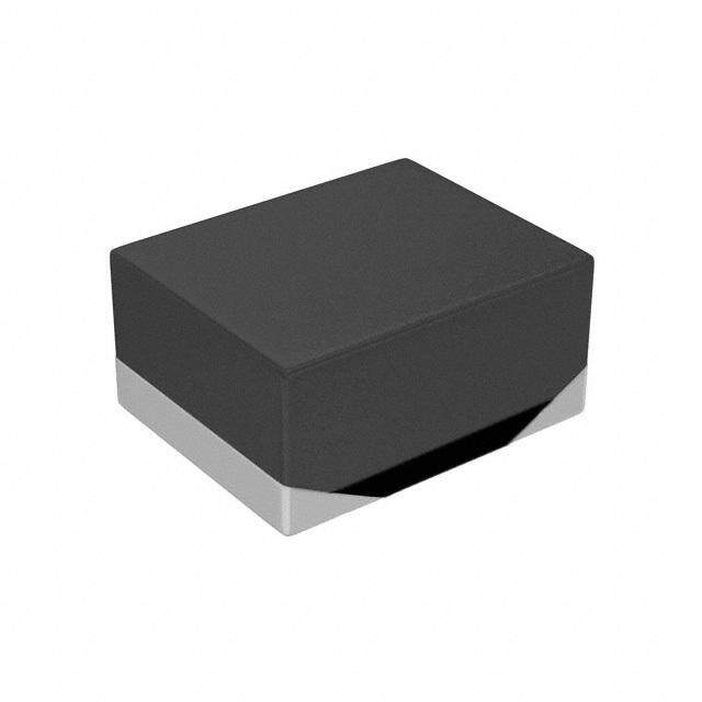
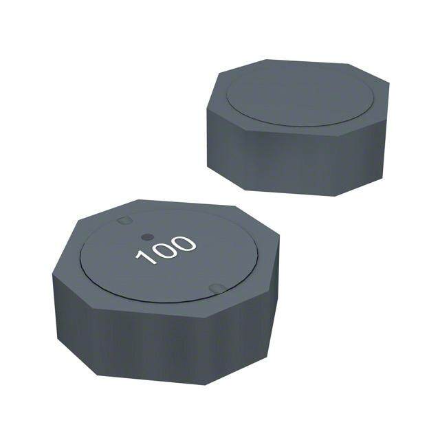
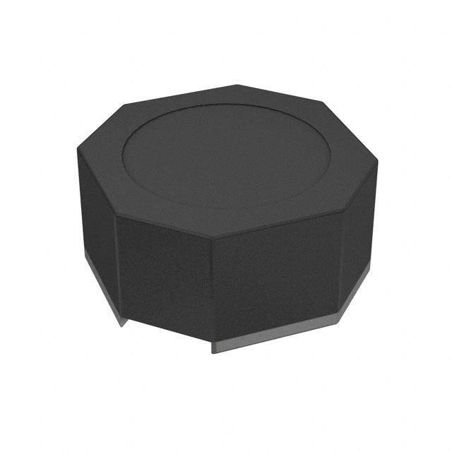
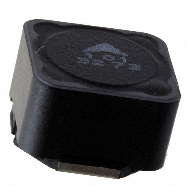
ICGOO电子元器件商城为您提供DR124-4R7-R由Bussmann/Cooper设计生产,在icgoo商城现货销售,并且可以通过原厂、代理商等渠道进行代购。 DR124-4R7-R价格参考。Bussmann/CooperDR124-4R7-R封装/规格:固定值电感器, 4.7µH 屏蔽 绕线 电感器 6.5A 16.2 毫欧最大 非标准 。您可以下载DR124-4R7-R参考资料、Datasheet数据手册功能说明书,资料中有DR124-4R7-R 详细功能的应用电路图电压和使用方法及教程。
| 参数 | 数值 |
| 产品目录 | |
| DC电阻(DCR) | 16.2 毫欧最大 |
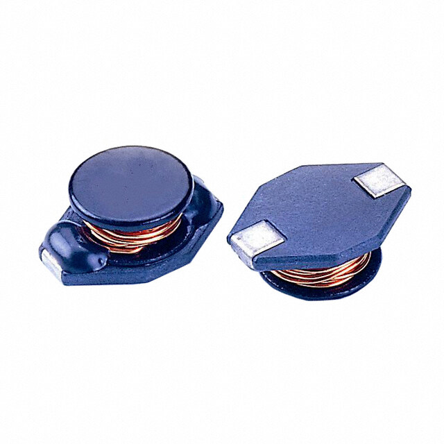
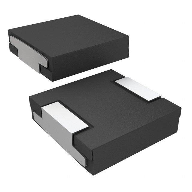
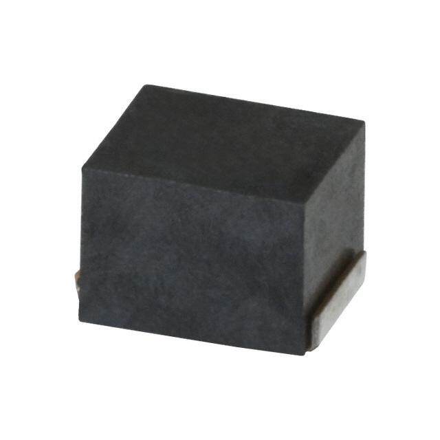
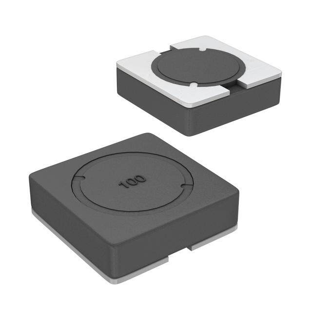
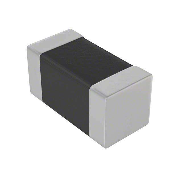
| 描述 | INDUCTOR POWER SHIELD 4.7UH SMD |
| 产品分类 | |
| 品牌 | Eaton Bussmann |
| 数据手册 | |
| 产品图片 |
|
| 产品型号 | DR124-4R7-R |
| rohs | 无铅 / 符合限制有害物质指令(RoHS)规范要求 |
| 产品系列 | DR124 |
| 不同频率时的Q值 | - |
| 产品 | Power Inductors |
| 产品培训模块 | http://www.digikey.cn/PTM/IndividualPTM.page?site=cn&lang=zhs&ptm=26315 |
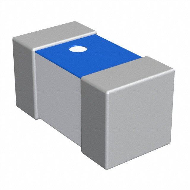
| 产品目录绘图 |
|
| 产品目录页面 | |
| 产品种类 | SMD Low Profile Power Inductors |
| 供应商器件封装 | - |
| 其它名称 | 513-1430-1 |
| 包装 | 剪切带 (CT) |
| 单位重量 | 3.175 g |
| 商标 | Coiltronics / Cooper Bussmann |
| 外壳宽度 | 12.5 mm |
| 外壳长度 | 12.5 mm |
| 外壳高度 | 4.5 mm |
| 大小/尺寸 | 0.492" 长 x 0.492" 宽(12.50mm x 12.50mm) |
| 安装类型 | 表面贴装 |
| 容差 | ±20% |
| 封装 | Reel |
| 封装/外壳 | 非标准 |
| 屏蔽 | 屏蔽 |
| 工作温度 | -40°C ~ 125°C |
| 工作温度范围 | - 40 C to + 125 C |
| 工厂包装数量 | 750 |
| 最大直流电流 | 7.65 A |
| 最大直流电阻 | 16.2 mOhms |
| 材料-磁芯 | 铁氧体 |
| 标准包装 | 1 |
| 测试频率 | 100 kHz |
| 电感 | 4.7µH |
| 电流-饱和值 | 7.65A |
| 端接类型 | SMD/SMT |
| 类型 | 绕线 |
| 系列 | DR124 |
| 芯体材料 | Ferrite |
| 频率-测试 | 100kHz |
| 频率-自谐振 | - |
| 额定电流 | 6.5A |
| 高度-安装(最大值) | 0.177"(4.50mm) |


- 商务部:美国ITC正式对集成电路等产品启动337调查
- 曝三星4nm工艺存在良率问题 高通将骁龙8 Gen1或转产台积电
- 太阳诱电将投资9.5亿元在常州建新厂生产MLCC 预计2023年完工
- 英特尔发布欧洲新工厂建设计划 深化IDM 2.0 战略
- 台积电先进制程称霸业界 有大客户加持明年业绩稳了
- 达到5530亿美元!SIA预计今年全球半导体销售额将创下新高
- 英特尔拟将自动驾驶子公司Mobileye上市 估值或超500亿美元
- 三星加码芯片和SET,合并消费电子和移动部门,撤换高东真等 CEO
- 三星电子宣布重大人事变动 还合并消费电子和移动部门
- 海关总署:前11个月进口集成电路产品价值2.52万亿元 增长14.8%


PDF Datasheet 数据手册内容提取
Effective March 2019 Technical Data 4141 Supersedes September 2017 DR124 High power density, high efficiency, low profile shielded drum core power inductors Applications • Notebook power • LCD panels • Desktop and servers • DVD players and portable power devices • DC-DC Converters • Buck, boost, forward, and resonant converters • Noise filtering and filter chokes Environmental Data • Storage temperature range (Component): -40 °C to +125 °C Product features • Operating temperature range: -40 °C to +125 °C • Low profile surface mount inductor (ambient plus self-temperature rise) • 12.5 mm x 12.5 mm x 4.5 mm shielded • Solder reflow temperature: drum core J-STD-020 (latest revision) compliant • Inductance range from 0.47 µH to 1000 µH • Current range from 0.44 A to 24.4 A • Frequency range up to 1 MHz Pb HHALOFGEN • Ferrite core material FREE
Technical Data 4141 DR124 Effective March 2019 High power density, high efficiency, low profile shielded drum core power inductors Product specifications Rated DCR DCR Inductance OCL1 I 2 I 3 mΩ @20°C mΩ @ +20°C rms sat Part Number (μH) μH±20% (A) (A) Typ Max K-factor4 DR124-R47-R 0.47 0.42 16.0 24.40 2.2 2.7 17.51 DR124-1R0-R 1.0 0.83 13.9 18.00 3.00 3.6 12.50 DR124-1R5-R 1.5 1.37 11.1 14.00 4.75 5.7 9.73 DR124-2R2-R 2.2 2.04 9.1 11.45 5.92 7.1 7.96 DR124-3R9-R 3.9 3.80 7.0 8.40 12.50 15.0 5.84 DR124-4R7-R 4.7 4.88 6.5 7.65 13.50 16.2 5.15 DR124-6R8-R 6.8 6.10 5.6 6.47 18.06 21.7 4.61 DR124-8R2-R 8.2 7.45 5.2 6.22 21.67 26.0 4.17 DR124-100-R 10 8.94 4.5 5.80 23.33 28.0 3.81 DR124-120-R 12 11.5 4.1 4.96 31.67 38.0 3.50 DR124-150-R 15 14.2 3.6 4.62 37.30 44.8 3.02 DR124-180-R 18 16.2 3.4 4.32 46.97 56.4 2.82 DR124-220-R 22 20.7 3.2 3.83 53.99 64.8 2.50 DR124-270-R 27 25.7 2.8 3.44 66.67 80.0 2.24 DR124-330-R 33 31.2 2.6 3.12 80.83 97.0 2.04 DR124-390-R 39 37.3 2.3 2.85 110.00 132.0 1.86 DR124-470-R 47 44.0 2.2 2.63 124.66 149.6 1.72 DR124-560-R 56 54.9 2.0 2.35 144.32 173.2 1.54 DR124-680-R 68 67.1 1.8 2.13 183.33 220.0 1.39 DR124-820-R 82 80.5 1.7 1.94 212.72 255.3 1.27 DR124-101-R 100 95.1 1.5 1.79 256.67 308.0 1.17 DR124-121-R 120 111 1.3 1.65 311.18 373.4 1.08 DR124-151-R 150 146 1.3 1.44 371.02 445.2 0.94 DR124-181-R 180 179 1.1 1.30 501.66 602.0 0.87 DR124-221-R 220 216 1.0 1.15 558.00 669.6 0.77 DR124-271-R 270 256 0.88 1.09 725.00 870.0 0.71 DR124-331-R 330 327 0.83 0.92 825.00 990.0 0.63 DR124-471-R 470 460 0.68 0.74 1242.50 1491.0 0.53 DR124-681-R 680 669 0.56 0.65 1845.83 2215.0 0.45 DR124-821-R 820 825 0.53 0.62 2109.17 2351.0 0.40 DR124-102-R 1000 998 0.44 0.53 2898.00 3477.00 0.37 1. Open Circuit Inductance Test Parameters: 100 kHz, 0.25 V, 0.0 Adc. 4. K-factor: Used to determine B for core loss (see graph). p-p 2. I : DC current for an approximate ∆T of 40 °C without core loss. Derating is B = K*L*∆I, B (mT), K: (K factor from table), L: (Inductance in μH), rms p-p p-p necessary for AC currents. PCB layout, trace thickness and width, air-flow, ∆I (Peak to peak ripple current in Amps). and proximity of other heat generating components will affect the 5. Part Number Definition: DR124-xxx-R temperature rise. It is recommended that the temperature of the part not - DR124 = Product code and size; -xxx = Inductance value in uH; exceed +125 °C under worst case operating conditions verified in the end - R = decimal point; If no R is present, third character = # of zeros. application. - “-R” suffix = RoHS compliant 3. I Amps peak for approximately 25% rolloff (@ +25 °C). sat 2 www.eaton.com/electronics
DR124 Technical Data 4141 High power density, high efficiency, low profile shielded drum Effective March 2019 core power inductors Dimensions- mm BOTTOM VIEW FRONT VIEW TOP VIEW RECOMMENDED PCB LAYOUT SCHEMATIC 2.05 Typ. 13.8 5T.y0p0 1 2 1M2.a5x0 M4a.5x DR124-### 1 1 2 12.50 wwllyy R 5.50 Max 2 10 3.85 Dimensions are in millimeters. wwlly = Date code, R = Revision level. Do not route traces or vias underneath the inductor. Packaging- mm 1.5 dia 1.5 dia +0.1/-0.0 min A 1.75 4.0 11 BAoo==1133..22 mmmm 12.6 Bo B1 wwllyy RDR124-### 24.0 A1=10mm B1=10 mm Ko=5.2 mm Ko A1 16.0 A Ao SECTION A-A User direction of feed Parts packaged on 13" Diameter reel, 750 parts per reel. Temperature rise vs. total loss 120 100 C) ° 80 e ( s Ri e 60 ur at er 40 p m e T 20 0 0 0.4 0.8 1.2 1.6 2 Total Power Loss (W) www.eaton.com/electronics 3
Technical Data 4141 DR124 Effective March 2019 High power density, high efficiency, low profile shielded drum core power inductors Core loss vs. Bp-p 100 500 kHz 1 MHz 300 kHz 10 200 kHz 100 kHz 1 ) W ( s s o 0.1 L e r o C 0.01 0.001 0.0001 1 10 100 1000 Bp-p (mT) Inductance characteristics OCL vs. Isat 120.0 100.0 -40 °C 80.0 L C +25 °C O 60.0 % +85 °C 40.0 20.0 0.0 0.0 20.0 40.0 60.0 80.0 100.0 120.0 % Isat 4 www.eaton.com/electronics
DR124 High power density, high efficiency, low profile shielded drum Technical Data 4141 core power inductors Effective March 2019 Solder reflow profile TP Table 1 - Standard SnPb Solder (Tc) TC -5°C Max. Ramp Up Rate = 3°C/s tP Volume Volume Package mm3 mm3 Max. Ramp Down Rate = 6°C/s Thickness <350 ≥350 TL <2.5mm) 235°C 220°C Preheat t ≥2.5mm 220°C 220°C A e Tsmax atur Table 2 - Lead (Pb) Free Solder (Tc) per Volume Volume Volume Tem Tsmin ts PThacickkangees s m<3m503 m35m03 - 2000 m>2m003 0 <1.6mm 260°C 260°C 260°C 1.6 – 2.5mm 260°C 250°C 245°C >2.5mm 250°C 245°C 245°C 25°C Time 25°C to Peak Time Reference JDEC J-STD-020 Profile Feature Standard SnPb Solder Lead (Pb) Free Solder Preheat and Soak • Temperature min. (Tsmin) 100°C 150°C • Temperature max. (Tsmax) 150°C 200°C • Time (Tsmin to Tsmax) (ts) 60-120 Seconds 60-120 Seconds Average ramp up rate Tsmax to Tp 3°C/ Second Max. 3°C/ Second Max. Liquidous temperature (Tl) 183°C 217°C Time at liquidous (tL) 60-150 Seconds 60-150 Seconds Peak package body temperature (TP)* Table 1 Table 2 Time (tp)** within 5 °C of the specified classification temperature (Tc) 20 Seconds** 30 Seconds** Average ramp-down rate (Tp to Tsmax) 6°C/ Second Max. 6°C/ Second Max. Time 25°C to Peak Temperature 6 Minutes Max. 8 Minutes Max. * Tolerance for peak profile temperature (Tp) is defined as a supplier minimum and a user maximum. ** Tolerance for time at peak profile temperature (tp) is defined as a supplier minimum and a user maximum. Life Support Policy: Eaton does not authorize the use of any of its products for use in life support devices or systems without the express written approval of an officer of the Company. Life support systems are devices which support or sustain life, and whose failure to perform, when properly used in accordance with instructions for use provided in the labeling, can be reasonably expected to result in significant injury to the user. Eaton reserves the right, without notice, to change design or construction of any products and to discontinue or limit distribution of any products. Eaton also reserves the right to change or update, without notice, any technical information contained in this bulletin. Eaton Electronics Division 1000 Eaton Boulevard Cleveland, OH 44122 United States www.eaton.com/electronics © 2019 Eaton All Rights Reserved Eaton is a registered trademark. Printed in USA Publication No. 4141 BU-SB14114 All other trademarks are property March 2019 of their respective owners.