ICGOO在线商城 > 分立半导体产品 > 二极管 - 整流器 - 阵列 > DPG60C400HB
 Datasheet下载
- 型号: DPG60C400HB
- 制造商: IXYS
- 库位|库存: xxxx|xxxx
- 要求:
| 数量阶梯 | 香港交货 | 国内含税 |
| +xxxx | $xxxx | ¥xxxx |
查看当月历史价格
查看今年历史价格
DPG60C400HB产品简介:
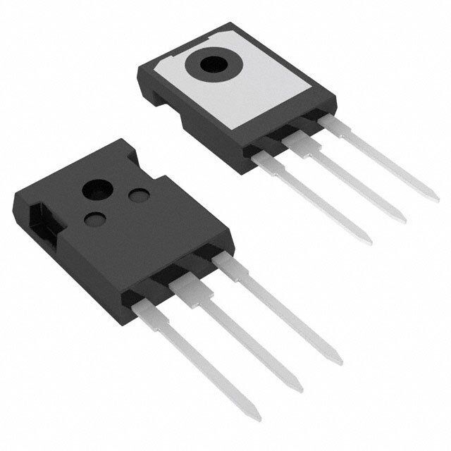
ICGOO电子元器件商城为您提供DPG60C400HB由IXYS设计生产,在icgoo商城现货销售,并且可以通过原厂、代理商等渠道进行代购。 DPG60C400HB价格参考¥34.84-¥34.84。IXYSDPG60C400HB封装/规格:二极管 - 整流器 - 阵列, Diode Array 1 Pair Common Cathode Standard 400V 30A Through Hole TO-247-3。您可以下载DPG60C400HB参考资料、Datasheet数据手册功能说明书,资料中有DPG60C400HB 详细功能的应用电路图电压和使用方法及教程。
IXYS品牌的DPG60C400HB是一种二极管整流器阵列,广泛应用于电力电子领域。以下是其主要应用场景:

1. 电源设计:该器件适用于开关电源(SMPS)、AC-DC和DC-DC转换器中,用于整流和续流功能,提高电源效率并降低能耗。

2. 电机驱动:在电机控制电路中,DPG60C400HB可用于整流和保护,支持工业电机、家用电器电机及电动车电机的高效运行。

3. 再生能源系统:如太阳能逆变器和风力发电系统中,该整流器阵列可将不稳定的交流电转换为稳定的直流电,以供储能或直接使用。

4. 不间断电源(UPS):在UPS系统中,该器件用于电池充电和逆变过程中的整流操作,确保系统的稳定性和可靠性。

5. 通信设备:在通信基站和其他电信设备中,DPG60C400HB能够提供高效的电源管理和电压调节。

6. 汽车电子:适用于车载充电器、LED照明驱动及各类汽车电子控制系统,满足汽车行业对高可靠性和高效能的需求。

7. 工业自动化:在PLC、变频器和其他工业自动化设备中,该整流器阵列可实现精确的功率控制和转换。

8. 消费类电子产品:如电视、音响设备等,需要高效整流和低功耗解决方案时,此器件亦可胜任。

DPG60C400HB凭借其高耐压(400V)、大电流承载能力(60A峰值)以及低正向压降特性,在上述应用中表现出色,同时具备出色的热性能和可靠性,适合各种严苛的工作环境。
| 参数 | 数值 |
| 产品目录 | |
| 描述 | DIODE ARRAY 400V 30A TO247二极管 - 通用,功率,开关 60 Amps 400V |
| 产品分类 | 二极管,整流器 - 阵列分离式半导体 |
| 品牌 | IXYS |
| 产品手册 | |
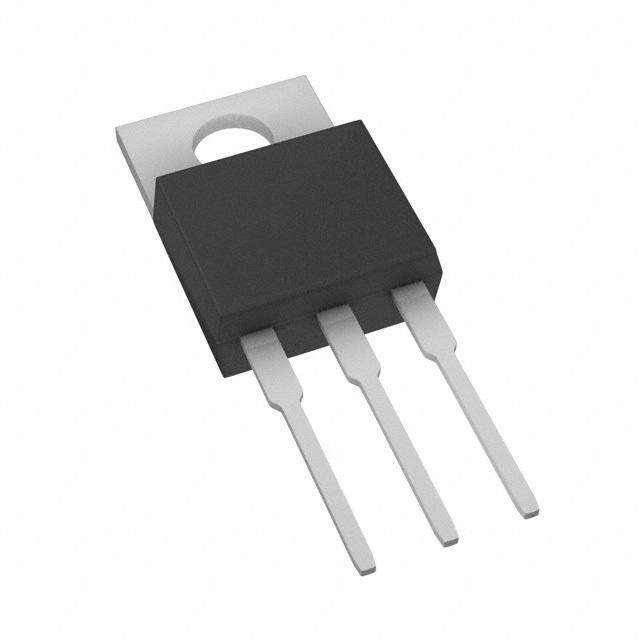
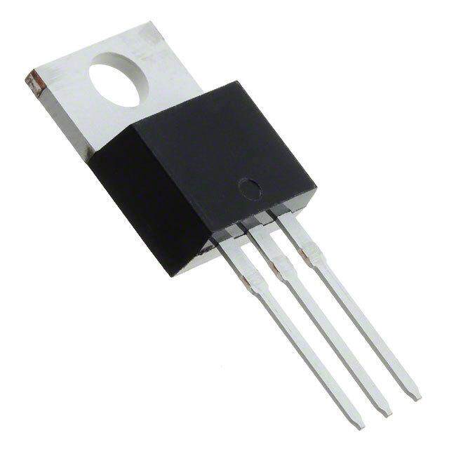
| 产品图片 |
|
| rohs | 符合RoHS无铅 / 符合限制有害物质指令(RoHS)规范要求 |
| 产品系列 | 二极管与整流器,二极管 - 通用,功率,开关,IXYS DPG60C400HBHiPerFRED™ |
| 数据手册 | |
| 产品型号 | DPG60C400HB |
| 不同If时的电压-正向(Vf) | 1.41V @ 30A |
| 不同 Vr时的电流-反向漏电流 | 1µA @ 400V |
| 二极管类型 | 标准 |
| 二极管配置 | 1 对共阴极 |
| 产品 | Switching Diodes |
| 产品种类 | 二极管 - 通用,功率,开关 |
| 供应商器件封装 | TO-247AD |
| 包装 | 管件 |
| 单位重量 | 6.500 g |
| 反向恢复时间(trr) | 45ns |
| 商标 | IXYS |
| 安装类型 | 通孔,径向 |
| 安装风格 | Through Hole |
| 封装 | Tube |
| 封装/外壳 | TO-247-3 |
| 封装/箱体 | TO-247-3 |
| 峰值反向电压 | 400 V |
| 工作温度范围 | - 55 C to + 150 C |
| 工厂包装数量 | 30 |
| 恢复时间 | 45 ns |
| 最大功率耗散 | 160 W |
| 最大反向漏泄电流 | 0.2 mA |
| 最大工作温度 | + 150 C |
| 最大浪涌电流 | 360 A |
| 最小工作温度 | - 55 C |
| 标准包装 | 30 |
| 正向电压下降 | 1.13 V |
| 正向连续电流 | 30 A |
| 热阻 | 0.25°C/W Cs |
| 电压-DC反向(Vr)(最大值) | 400V |
| 电流-平均整流(Io)(每二极管) | 30A |
| 系列 | DPG60C400 |
| 速度 | 快速恢复 =< 500 ns,> 200mA(Io) |
| 配置 | Dual Common Cathode |


- 商务部:美国ITC正式对集成电路等产品启动337调查
- 曝三星4nm工艺存在良率问题 高通将骁龙8 Gen1或转产台积电
- 太阳诱电将投资9.5亿元在常州建新厂生产MLCC 预计2023年完工
- 英特尔发布欧洲新工厂建设计划 深化IDM 2.0 战略
- 台积电先进制程称霸业界 有大客户加持明年业绩稳了
- 达到5530亿美元!SIA预计今年全球半导体销售额将创下新高
- 英特尔拟将自动驾驶子公司Mobileye上市 估值或超500亿美元
- 三星加码芯片和SET,合并消费电子和移动部门,撤换高东真等 CEO
- 三星电子宣布重大人事变动 还合并消费电子和移动部门
- 海关总署:前11个月进口集成电路产品价值2.52万亿元 增长14.8%


PDF Datasheet 数据手册内容提取
DPG60C400HB HiPerFRED² V = 400V RRM I =2x 30A FAV t = 45ns rr High Performance Fast Recovery Diode Low Loss and Soft Recovery Common Cathode Part number DPG60C400HB Backside: cathode 1 2 3 Features / Advantages: Applications: Package: TO-247 ● Planar passivated chips ● Antiparallel diode for high frequency ● Industry standard outline ● Very low leakage current switching devices ● RoHS compliant ● Very short recovery time ● Antisaturation diode ● Epoxy meets UL 94V-0 ● Improved thermal behaviour ● Snubber diode ● Very low Irm-values ● Free wheeling diode ● Very soft recovery behaviour ● Rectifiers in switch mode power ● Avalanche voltage rated for reliable operation supplies (SMPS) ● Soft reverse recovery for low EMI/RFI ● Uninterruptible power supplies (UPS) ● Low Irm reduces: - Power dissipation within the diode - Turn-on loss in the commutating switch IXYS reserves the right to change limits, conditions and dimensions. Data according to IEC 60747and per semiconductor unless otherwise specified 20131101a ©2013 IXYS all rights reserved
DPG60C400HB Fast Diode Ratings Symbol Definition Conditions min. typ. max. Unit V max. non-repetitive reverse blocking voltage T = 25°C 400 V RSM VJ V max. repetitive reverse blocking voltage T = 25°C 400 V RRM VJ I reverse current, drain current V = 4 0 0 V T = 25°C 1 µA R R VJ V = 4 0 0 V T = 1 5 0 °C 0.2 mA R VJ V forward voltage drop I = 3 0 A T = 25°C 1.41 V F F VJ I = 6 0 A 1.69 V F I = 3 0 A T = 1 5 0 °C 1.13 V F VJ I = 6 0 A 1.46 V F I average forward current T = 1 3 5 °C T = 1 7 5 °C 30 A FAV C VJ rectangular d =0.5 V threshold voltage T = 1 7 5 °C 0.76 V F0 VJ for power loss calculation only r slope resistance 10.7 mΩ F R thermal resistance junction to case 0.95 K/W thJC R thermal resistance case to heatsink 0.25 K/W thCH P total power dissipation T = 25°C 160 W tot C I max. forward surge current t = 10 ms; (50 Hz), sine; V = 0 V T = 45°C 360 A FSM R VJ C junction capacitance V = 2 0 0 V f = 1 MHz T = 25°C 39 pF J R VJ I max. reverse recovery current T = 25°C 4 A RM VJ I = 30A; V = 270V T =125°C 8.5 A F R VJ t reverse recovery time -di /dt = 200A/µs T = 25°C 45 ns rr F VJ T =125°C 85 ns VJ IXYS reserves the right to change limits, conditions and dimensions. Data according to IEC 60747and per semiconductor unless otherwise specified 20131101a ©2013 IXYS all rights reserved
DPG60C400HB Package TO-247 Ratings Symbol Definition Conditions min. typ. max. Unit I RMS current per terminal 1) 50 A RMS T virtual junction temperature -55 175 °C VJ T operation temperature -55 150 °C op T storage temperature -55 150 °C stg Weight 6 g M mounting torque 0.8 1.2 Nm D F mounting force with clip 20 120 N C Product Marking Part number D= Diode P= HiPerFRED G = extreme fast 60= Current Rating [A] C= Common Cathode 400= Reverse Voltage [V] Logo IXYS HB = TO-247AD (3) PartNo. XXXXXXXXX AssemblyLine Zyyww abcd AssemblyCode DateCode Ordering Part Number Marking on Product Delivery Mode Quantity Code No. Standard DPG60C400HB DPG60C400HB Tube 30 505825 Similar Part Package Voltage class DPG60C400QB TO-3P (3) 400 DPG80C400HB TO-247AD (3) 400 Equivalent Circuits for Simulation * on die level T V J =175°C I V R Fast 0 0 Diode V threshold voltage 0.76 V 0 max R slope resistance * 8.1 mΩ 0 max IXYS reserves the right to change limits, conditions and dimensions. Data according to IEC 60747and per semiconductor unless otherwise specified 20131101a ©2013 IXYS all rights reserved
DPG60C400HB Outlines TO-247 A D2 E A2 ØP Ø P1 Q S Sym. Inches Millimeter min. max. min. max. A 0.185 0.209 4.70 5.30 D1 A1 0.087 0.102 2.21 2.59 D A2 0.059 0.098 1.50 2.49 D 0.819 0.845 20.79 21.45 2x E2 E 0.610 0.640 15.48 16.24 4 E2 0.170 0.216 4.31 5.48 e 0.215BSC 5.46BSC 1 2 3 L 0.780 0.800 19.80 20.30 L1 - 0.177 - 4.49 L1 E1 ØP 0.140 0.144 3.55 3.65 Q 0.212 0.244 5.38 6.19 S 0.242BSC 6.14BSC L b 0.039 0.055 0.99 1.40 b2 0.065 0.094 1.65 2.39 b4 0.102 0.135 2.59 3.43 c 0.015 0.035 0.38 0.89 2x b2 C D1 0.515 - 13.07 - 3x b D2 0.020 0.053 0.51 1.35 b4 A1 E1 0.530 - 13.45 - 2x e ØP1 - 0.29 - 7.39 1 2 3 IXYS reserves the right to change limits, conditions and dimensions. Data according to IEC 60747and per semiconductor unless otherwise specified 20131101a ©2013 IXYS all rights reserved
DPG60C400HB Fast Diode 80 1.0 TVJ =125°C 60A 20 TVJ=125°C 60A 70 VR =270 V VR = 270 V 30A 60 0.8 30A 16 15A 50 Q IF 40 TVJ=150°C rr 0.6 IRR 15A 12 [μC] [A]30 [A] 20 0.4 8 25°C 10 0.2 4 0.0 0.4 0.8 1.2 1.6 2.0 0 200 400 600 0 200 400 600 VF [V] -diF/dt [A/μs] -diF/dt [A/μs] Fig.1 Forwardcurrent Fig.2 Typ.reverserecov.charge Fig.3 Typ.reverserecoverycurrent I versusV Q versus-di /dt I versus-di /dt F F rr F RR F 1.6 140 700 16 T =125°C T =125°C VJ t VJ V 1.4 VR = 270 V 600 fr VR =270 V FR 14 120 I = 30 A 1.2 F 500 12 1.0 100 trr tfr 400 10 Kf0.8 V FR [ns] 80 [ns]300 8 0.6 I [V] RR 15A 200 6 0.4 60 30A 0.2 Qrr 60A 100 4 0.0 40 0 2 0 40 80 120 160 0 200 400 600 0 200 400 600 TVJ [°C] -diF/dt [A/μs] -diF/dt [A/μs] Fig.4 Typ.dynamicparameters Fig.5 Typ.reverserecov.time Fig.6 Typ.forwardrecov.voltage Q ,I versusT t versus-di /dt V &timet versusdi /dt rr RR VJ rr F FR fr F 50 1.0 T =125°C 60A VJ V = 270 V R 40 0.8 30A 30 0.6 Z 15A thJC E rec [K/W] 20 0.4 [μJ] 10 0.2 0 0.0 0 200 400 600 1 10 100 1000 10000 -di /dt [A/μs] t [ms] F Fig.7 Typ.recoveryenergy Fig.8 Transientthermalimpedancejunctiontocase E versus-di /dt rec F IXYS reserves the right to change limits, conditions and dimensions. Data according to IEC 60747and per semiconductor unless otherwise specified 20131101a ©2013 IXYS all rights reserved