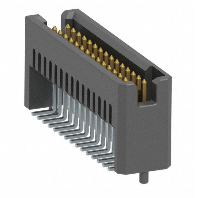
ICGOO在线商城 > 连接器,互连器件 > 矩形连接器 - 针座,公插针 > DF60-2P-10.16DSA(26)
- 型号: DF60-2P-10.16DSA(26)
- 制造商: Hirose Electric
- 库位|库存: xxxx|xxxx
- 要求:
| 数量阶梯 | 香港交货 | 国内含税 |
| +xxxx | $xxxx | ¥xxxx |
查看当月历史价格
查看今年历史价格
DF60-2P-10.16DSA(26)产品简介:
ICGOO电子元器件商城为您提供DF60-2P-10.16DSA(26)由Hirose Electric设计生产,在icgoo商城现货销售,并且可以通过原厂、代理商等渠道进行代购。 DF60-2P-10.16DSA(26)价格参考。Hirose ElectricDF60-2P-10.16DSA(26)封装/规格:矩形连接器 - 针座,公插针, 2 位 接头 连接器 0.400"(10.16mm) 通孔 金。您可以下载DF60-2P-10.16DSA(26)参考资料、Datasheet数据手册功能说明书,资料中有DF60-2P-10.16DSA(26) 详细功能的应用电路图电压和使用方法及教程。
| 参数 | 数值 |
| 产品目录 | |
| 描述 | CONN HDR 10.16MM VERT PCB 2POS电源到板 2 Pin Header Straight DSA type |
| 产品分类 | |
| 品牌 | Hirose Electric Co Ltd |
| 产品手册 | |
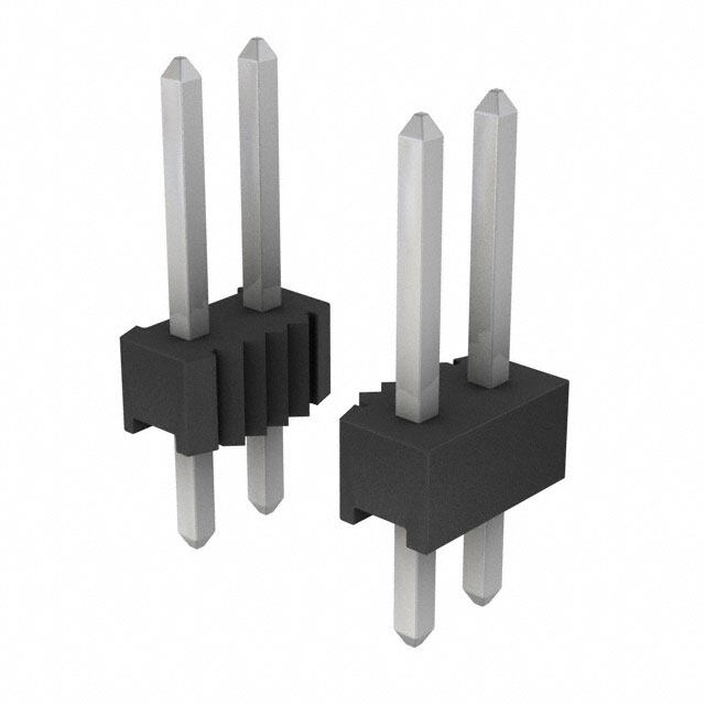
| 产品图片 |
|
| rohs | 符合RoHS无铅 / 符合限制有害物质指令(RoHS)规范要求 |
| 产品系列 | 电源到板,Hirose Connector DF60-2P-10.16DSA(26)DF60 |
| 数据手册 | |
| 产品型号 | DF60-2P-10.16DSA(26) |
| 产品种类 | 电源到板 |
| 产品类型 | Connectors |
| 位置数量 | 2 |
| 其它名称 | H122135 |
| 加载的针脚数 | 全部 |
| 包装 | 托盘 |
| 商标 | Hirose Connector |
| 外壳材料 | Polybutylene Terephthalate (PBT) |
| 安装类型 | 通孔 |
| 安装角 | Straight |
| 安装风格 | - |
| 封装 | Tray |
| 工作温度范围 | - 55 C to + 105 C |
| 排数 | 1 |
| 排距 | - |
| 标准包装 | 96 |
| 特性 | 板导轨 |
| 特色产品 | http://www.digikey.cn/product-highlights/zh/df60-series/52196 |
| 电压额定值 | 1 kV |
| 电流额定值 | 40 A |
| 端接 | |
| 端接类型 | Through Hole |
| 系列 | DF60 |
| 紧固类型 | 锁存器支座 |
| 线规量程 | 12-8 |
| 节距 | 10.16 mm |
| 触头类型 | 公形引脚 |
| 触头配接长度 | - |
| 触头镀层 | 金 |
| 触头镀层厚度 | 8µin (0.20µm) |
| 触点材料 | Copper |
| 触点电镀 | Gold |
| 触点类型 | Pin (Male) |
| 连接器类型 | 接头,有罩 |
| 配套产品 | /product-detail/zh/DF60-2S-10.16C/H122147-ND/4552172 |
| 针脚数 | 2 |
| 间距 | 0.400"(10.16mm) |
| 颜色 | 黑 |




- 商务部:美国ITC正式对集成电路等产品启动337调查
- 曝三星4nm工艺存在良率问题 高通将骁龙8 Gen1或转产台积电
- 太阳诱电将投资9.5亿元在常州建新厂生产MLCC 预计2023年完工
- 英特尔发布欧洲新工厂建设计划 深化IDM 2.0 战略
- 台积电先进制程称霸业界 有大客户加持明年业绩稳了
- 达到5530亿美元!SIA预计今年全球半导体销售额将创下新高
- 英特尔拟将自动驾驶子公司Mobileye上市 估值或超500亿美元
- 三星加码芯片和SET,合并消费电子和移动部门,撤换高东真等 CEO
- 三星电子宣布重大人事变动 还合并消费电子和移动部门
- 海关总署:前11个月进口集成电路产品价值2.52万亿元 增长14.8%
(SN).jpg)
PDF Datasheet 数据手册内容提取
65A 10.16mm pitch Wire-to-Board Connectors for Internal Power Supply DF60 Series (UL, C-UL, TÜV certified product) Unique locking mechanism is contained inside the header Socket and header design avoids short-circuit between adjacent contacts. Guide keys prevent incorrect insertion d. e v r e s e Molded pins give a R temporary hold and s assure proper orientation ht of the connector. Fig.1 g Ri All ■Features D. ● Lock structure T 1. High current capacity L [A-A] O., Capable of going to a max. of 65A when using C 8 AWG with the single position connector. Crimp contact C (Please refer to the chart for the rated current in A RI other pin counts.) T EC 2. Secure lock mechanism ensures A Lock parts of the plug and EL complete mating header start E to engage. A secure lock mechanism with a clear tactile and S O audible click prevents insufficient mating. (Fig.2) R HI 3. Highly reliable 5-point contact structure No contact yet. 8 1 Three independent contact springs provide a 0 Header contact 2 secure contact with high contact reliability using ht 5-point of contact. (Fig.3) g yri 4. Molded lance design Fig.2 p Co The lance is actually part of the housing instead of 8 being part of the terminal. This prevents tangled 1 wires during assembly. 0 2 1. 5. Mis-insertion prevention for headers c. e The addition of a molded pin on the header allows D temporary mounting retention and prevents reverse mounting on the PCB. (Fig.1). (Right angle pin header has a metal fitting for this purpose) Three independent spring contacts provide a secure contact and a 6. Prevention of solder cracks high contact reliability with 5-points of contact. Glass-reinforced resin is used on pin header to Fig.3 prevent solder cracks due to thermal contraction. 7. Design Prevents short-circuits between contacts The wall structure between contacts isolates the contacts and prevents short circuits from occuring. (Fig.1) 8. Compliant to UL, C-UL and TÜV specifications 9. Glow Wire compliance(Compliant with IEC 60695-2-11) 10. Finger-safe (Electric shock prevention) type available In cases where the application will demand a high level of reliability, such as automotive, 2018.6r 1 please contact a company representative for further information.
DF60 Series●65A 10.16mm pitch Wire-to-Board Connectors for Internal Power Supply(UL, C-UL, TÜV certified product) ■Product Specifi cations No. of Contacts 8 AWG 10 AWG 12 AWG Operating Temperature -55~105ç (Note 2) 1 50A 40A 31A Operating Humidity Range 20~80% Current 2 Storage Temperature Range -10~60ç (Note 3) 45A 35A 28A Rating 3 Storage Humidity Range 40~70% Ratings (Note 1) 4 UL/TÜV fi le No. and certifi cation No. UL : E52653 5 42A 33A 27A C-UL : E52653 6 TÜV : R50244085 Voltage Rating AC/DC 1,000V R5040864 (DF60F) Current Rating Voltage Rating 8 AWG (2 contacts) Derating Curve UL See below table AC/DC 600V Basic Curve ved. C-UL See upper table AC/DC 600V 120 Derating Curve r (Δt=30ç) ese TÜV See upper table AC/DC 600V 100 R )80 All Rights CUuLrr eSntta rnadtainrgd sof No. of C12ontacts 8 6A5WAG 105 A5WAG 1244 A50WAAG Current(A6400 D. (Ambient temperature : 3 50A 20 T 25ç) 4 L 55A 0 20 40 60 80 100 120 140 O., (Note 1) 5 45A 35A Ambient Temperature(℃) C 6 Note : The derating curve is derived from the basic curve C multiplied by the derating factor of 0.8. RI T Item Specifi cations Conditions C E 1. Insulation No less than 1,000Mø Measured at DC=1,000V L resistance E E 2. Withstand S voltage No fl ashover or breakdown AC 3,000V applied for 1 minute. O R 3. Contact HI resistance No more than 2mø Measured at 1A and not greater than 6V 8 4. Vibration Frequency 10 - 500Hz, accelerated velocity 98 m/s2, 201 Resistance No electrical discontinuity of 1μs or greater 2 hours for each of the three axis directions ht 5. Shock Accelerated velocity : 490m/s2, for11 ms, half-sine wave g No electrical discontinuity of 1μs or greater ri Resistance form in 3 directions, 3 times for each of the three directions y p 6. Moisture- Contact resistance : no more than 2mø ; Temperature : 40±2ç; humidity : 90 to 95%, left for 96 o C resistance insulation resistance : no less than 1,000Mø hours 018 7. Tcyecmlepserature Cinosnutlaatciot nre rseisstiastnacnec e: n: on om loerses t hthaann 2 1m,0ø0 0; Mø -55ç : 30 minutes→85ç : 30 minutes 25 cycles 2 1. 8.Durability Contact resistance No more than 2mø 30 mating/unmating cycles c. e D 9. Solder heat There should be no melting of the resin part Flow : 260ç, 10sec resistance which will infl uence the performance. Hand soldering : temperature of soldering iron at 350ç±10ç for 5 seconds Note 1 : This is the maximum current rating while all pins are powered or used as all power lines. If you split the current over multiple lines, please factor in your own safety margin. Note 2 : Includes the temperature rise of power lines. Note 3 : The storage condition refers to long-term storage of the product on the shelf before assembly. Please use the operating temperature for temporary storage such as pre-assembly and during shipping. ■Materials / Finish Component Part Material Finish UL Specifi cation Insulator PBT (glass-reinforced) Black UL94V-0 High conductivity copper Header Contact Gold plating − alloy Metal fi tting Brass Tin-plating − Crimp socket Insulator PBT (glass-reinforced) Black UL94V-0 In-line plug Insulator PBT (glass-reinforced) Black UL94V-0 High conductivity copper Crimp contact Contact Gold plating − alloy 2
DF60 Series●65A 10.16mm pitch Wire-to-Board Connectors for Internal Power Supply(UL, C-UL, TÜV certified product) ■Product Number Structure Refer to the chart below when determining the product specifications from the product number. Please select from the product numbers listed in this catalog when placing orders. ●Header Connector DF 60 F R − * P − 10.16 DSA ❶ ❷ ❸ ❹ ❺ ❻ ❼ ❽ ❶ Series Name : DF ❺ Number of contacts : 1, 2, 3, 4, 5, 6 ❷ Series No. : 60 ❻ Connector type P : Pin header ❸ Form type Blank : Standard ❼ Pitch : 10.16mm ed. F : Finger-safe ❽ Type of housing rv ❹ Guide key type Blank : Standard DSA : Straight pin header e s R : Another key shape DS : Right angle pin header e R s ht g Ri ●Socket Connector All DF 60 F R − * S − 10.16 C D. T ❶ ❷ ❸ ❹ ❺ ❻ ❼ ❽ L O., ❶ Series Name : DF ❺ Number of contacts : 1, 2, 3, 4, 5, 6 C ❷ Series No. : 60 ❻ Connector type S : Socket C RI ❸ Form type A : Standard ❼ Pitch : 10.16mm T F : Finger-safe C ❽ Type of housing E ❹ Guide key type Blank : Standard L C : Crimp socket E R : Another key shape E S O R HI ●In-line plug Connector 8 1 DF 60 F R − * EP − 10.16 C 0 2 ht ❶ ❷ ❸ ❹ ❺ ❻ ❼ ❽ g yri ❶ Series Name : DF ❺ Number of contacts : 1, 2, 3, 4, 5 p o C ❷ Series No. : 60 ❻ Connector type 8 ❸ Form type Blank : Standard EP : In-line plug 1 0 A : No flange ❼ Pitch : 10.16mm 2 F : Finger-safe 1. ❽ Type of housing c. ❹ Guide key type Blank : Standard De R : Another key shape C : Crimp socket ●Crimp Contact DF 60 A − 8 SCFA ❶ ❷ ❸ ❶ Type of connection ❸ Packaging styles Blank : Standard SCFA : Socket contact / reel A : Sequential SCA : Socket contact / loose ❷ Applicable wire size PCFA : In-line plug contact / reel 8 : 8 AWG 1012 : 10 to 12 AWG PCA : In-line plug contact / loose 3
DF60 Series●65A 10.16mm pitch Wire-to-Board Connectors for Internal Power Supply(UL, C-UL, TÜV certified product) ■Diagram of Connector Mating Combinations ●Standard Type Crimp socket Socket contact Straight pin header DF60A(R)-*S-10.16C (Note) DF60-*SC(F)A DF60(R)-*P-10.16DSA Note : R type (Another key shape) socket mates with R type plug / pin header. d. Right angle pin header ve DF60(R)-*P-10.16DS r e s e R s ht g Ri All D. T L In-line plug In-line plug contact O., DF60(A)(R)-*EP-10.16C DF60(A)-*PC(F)A C C RI T C E L E E S O R HI 8 1 0 2 ht g yri ●Finger-safe Type p Co Crimp socket Socket contact Straight pin header 8 DF60F(R)-*S-10.16C (Note) DF60-*SC(F)A DF60F(R)-*P-10.16DSA 1 0 Note : R type (Another key shape) socket mates with 2 1. R type plug / pin header. c. e D In-line plug In-line plug contact DF60F(R)-*EP-10.16C DF60(A)-*PC(F)A 4
DF60 Series●65A 10.16mm pitch Wire-to-Board Connectors for Internal Power Supply(UL, C-UL, TÜV certified product) ■Straight pin header 3 pos. 5 pos. PCB layout d. (Recommended thickness of PCB: t=1.6±0.1mm) e v er 5 D±0.05 s Res 2±0.0 4-R1±0.05 E±0 .05 ht g Ri TD. All ±0.05 Ø 1.8 ± 0.0 5 Connector outline O., L 5.8 P=120..5146±±00..0055 C C A±0.05 RI Headers with 1 to 4 pos. Headers with 5 to 6 pos. T C E B±0.4 B±0.4 OSE EL 12.2±0.4 1.45±0.2 A±0 .3P=10.16±0.2 12.2±0.4 1.45±0.2 P=1A0±.106.3±0.2 R 8 HI ±0.4 3 ±0.4 ght 201 15.7 2.95±0. Cavity.No A Contact No. 15.7 2.95±0.3Cavity.NoA Contact No. yri p o 2018 C 23.1±0.4 21.5±0.3 3.8±0.2 23.1±0.4 21.5±0.3 3.8±0.2 1. 3 2 1 5 4 3 2 1 c. e D 1±0.2 Ø2±0.2 1±0.2 Ø2±0.2 t=1±0.1 t=1±0.1 2.54±0.3 2.54±0.3 5.8±0.3 5.8±0.3 C± 0.3 C±0 .3 gold plating, tray packaging Standard Type Unit : mm Part No. HRS No. No. of Contacts A B C D E Quantity per package Guide key Color DF60-1P-10.16DSA(27) 680-3004-5 27 1 —— 15.2 9.55 12.2 7.78 160 DF60-2P-10.16DSA(27) 680-3005-8 27 2 10.16 22.36 19.71 22.36 17.94 96 DF60-3P-10.16DSA(27) 680-3001-7 27 3 20.32 32.52 29.87 32.52 28.1 64 Standard Black DF60-4P-10.16DSA(27) 680-3006-0 27 4 30.48 42.68 40.03 42.68 38.26 48 DF60-5P-10.16DSA(27) 680-3007-3 27 5 40.64 52.84 50.19 52.84 48.42 32 DF60-6P-10.16DSA(27) 680-3008-6 27 6 50.8 63 60.35 63 58.58 Standard Type [Color : Red] Part No. HRS No. No. of Contacts A B C D E Quantity per package Guide key Color DF60-2P-10.16DSA(45) 680-3005-8 45 2 10.16 22.36 19.71 22.36 17.94 96 Standard Red DF60-3P-10.16DSA(45) 680-3001-7 45 3 20.32 32.52 29.87 32.52 28.1 64 R Type Part No. HRS No. No. of Contacts A B C D E Quantity per package Guide key Color DF60R-3P-10.16DSA(27) 680-3038-7 27 3 20.32 32.52 29.87 32.52 28.1 64 Another key shape Gray Note : Please place orders in full lot quantities. 5
DF60 Series●65A 10.16mm pitch Wire-to-Board Connectors for Internal Power Supply(UL, C-UL, TÜV certified product) ■Right angle pin header 3 pos. 5 pos. PCB Layout d. (Recommended thickness of PCB: t=1.6±0.1mm) e B±0.4 eserv 2-Ø3±0.05 C±0.05 Connector outline R s ght 05 0.3 Ri ±0. 5± All 17.2 (2) 2 D. LT 2.54±0.05 6-Ø CO., P=10.16±0.05 A±0.05 1.8±0.0 5 C Headers with 1 to 4 pos. Headers with 5 to 6 pos. RI T B±0.4 B±0.4 C E L E E S 17.35±0.3 3.6±0.5 17.35±0.3 3.6±0.5 O A A HIR Cavity.No ±0.1 Cavity.No ±0.1 8 47 47 1 0. 0. 0 = = right 2 25±0.3 0.1t ±0.4 25±0.3 t0.1 ±0.4 y ± 2 ± 2 Cop 3 2 1 t=1 17. 5 4 3 2 1 t=1 17. Contact No. 8 1 20 3.8+-00..83 3.8+-00..83 1. c. e D 1±0.2 1±0.2 2.54±0.3 2.54±0.3 P=10.16±0.2 P=10.16±0.2 A±0.3 A±0.3 gold plating, C±0.3 C±0.3 tray packaging Standard Type Unit:mm Part No. HRS No. No. of Contacts A B C Quantity per package Guide key Color DF60-1P-10.16DS(27) 680-3015-1 27 1 —— 15.2 8.35 120 DF60-2P-10.16DS(27) 680-3016-4 27 2 10.16 22.36 15.51 72 DF60-3P-10.16DS(27) 680-3017-7 27 3 20.32 32.52 25.67 48 Standard Black DF60-4P-10.16DS(27) 680-3018-0 27 4 30.48 42.68 35.83 36 DF60-5P-10.16DS(27) 680-3019-2 27 5 40.64 52.84 45.99 24 DF60-6P-10.16DS(27) 680-3020-1 27 6 50.8 63 56.15 Standard Type [Color : Red] Part No. HRS No. No. of Contacts A B C Quantity per package Guide key Color DF60-2P-10.16DS(45) 680-3016-4 45 2 10.16 22.36 15.51 72 Standard Red R Type Part No. HRS No. No. of Contacts A B C Quantity per package Guide key Color DF60R-2P-10.16DS(27) 680-3043-7 27 2 10.16 22.36 15.51 72 Another key shape Gray DF60R-3P-10.16DS(27) 680-3044-0 27 3 20.32 32.52 25.67 48 Note : Please place orders in full lot quantities. 6
DF60 Series●65A 10.16mm pitch Wire-to-Board Connectors for Internal Power Supply(UL, C-UL, TÜV certified product) ■ In-line plug Standard Type No Flange Type 3 pos. 4 pos. The torque value for attaching screws is 49N Panel cutout d. e C±0.2 v er (B+1)±0.3 s e 13.5±0.3 R ghts Ø3.6±0.1 Ri All D. O., LT ±0.3 ±0.3 ±0.3 R0.5MAX 9 4 5 C C 17. 13. 8.4In-line plugs with 1 to 5 pos. Inline plug with 4 pos. RI T D±0.3 C E C±0.2 42.68±0.2 EL B±0.3 30.48±0.3 E A±0.3 P=10.16±0.2 S P=10.16±0.2 P=10.16±0. O R HI A 8 1 15.9±0.4 0 A Cavity.No 2 12.4±0.3 ht Cavity.No 15.9±0.4 g 12.4±0.3 ri y p 2018 Co ±0.4 6.8±0.311.2±0.3 ±04 38.6±0.4 c.1. 38.6 386 Contact No. De Contact No. 4 3 2 1 41.08±0.3 3 2 1 1 package = 100 pcs E±0.3 Standard Type Unit : mm Part No. HRS No. No. of Contacts A B C D E Guide key Color DF60-1EP-10.16C 680-3050-2 1 —— 15.2 23.7 32.2 10.6 DF60-2EP-10.16C 680-3025-5 2 —— 22.36 30.86 39.36 20.76 DF60-3EP-10.16C 680-3026-8 3 20.32 32.52 41.02 49.52 30.92 Standard Black DF60-4EP-10.16C 680-3027-0 4 30.48 42.68 51.18 59.68 41.08 DF60-5EP-10.16C 680-3028-3 5 40.64 52.84 61.34 69.84 51.24 Standard Type [Color : Red] Part No. HRS No. No. of Contacts A B C D E Guide key Color DF60-1EP-10.16C(15) 680-3050-2 15 1 —— 15.2 23.7 32.2 10.6 DF60-2EP-10.16C(15) 680-3025-5 15 2 —— 22.36 30.86 39.36 20.76 Standard Red DF60-3EP-10.16C(15) 680-3026-8 15 3 20.32 32.52 41.02 49.52 30.92 R Type Part No. HRS No. No. of Contacts A B C D E Guide key Color DF60R-2EP-10.16C 680-3053-0 2 —— 22.36 30.86 39.36 20.76 Another key shape Gray DF60R-3EP-10.16C 680-3054-0 3 20.32 32.52 41.02 49.52 30.92 No Flange Type Part No. HRS No. No. of Contacts Guide key Color DF60A-4EP-10.16C 680-3069-0 4 Standard Black Note : Bag packaging (100pcs/pack). Order by number of packs. 7
DF60 Series●65A 10.16mm pitch Wire-to-Board Connectors for Internal Power Supply(UL, C-UL, TÜV certified product) ■ Crimp socket ed. Crimp socket with 1 to 4 pos. Crimp socket with 5 to 6 pos. v r e s A±0.3 A±0.3 Re P=10.16±0.2 P=10.16±0.2 s ht g Ri 1 1 All Cavity No. Cavity No. D. T B±0.4 18±0.4 B±0.4 18±0.4 L O., C C 3 3 RI ±0. ±0. T 4 4 C 4. 4. 2 2 E L E E S O R HI 8 1 0 2 ht g ri y p o C 8 1 0 2 c.1. 3 2 1 5 4 3 2 1 e Contact No. Contact No. D 1 package = 100 pcs Standard Type Unit : mm Part No. HRS No. No. of Contacts A B Guide key Color DF60A-1S-10.16C 680-3058-0 1 —— 15.8 DF60A-2S-10.16C 680-3059-0 2 10.16 22.36 DF60A-3S-10.16C 680-3060-0 3 20.32 32.52 Standard Black DF60A-4S-10.16C 680-3061-0 4 30.48 42.68 DF60A-5S-10.16C 680-3076-0 5 40.64 52.84 DF60A-6S-10.16C 680-3077-0 6 50.8 63.0 Standard Type [Color : Red] Part No. HRS No. No. of Contacts A B Guide key Color DF60A-1S-10.16C(15) 680-3058-0 15 1 —— 15.8 DF60A-2S-10.16C(15) 680-3059-0 15 2 10.16 22.36 Standard Red DF60A-3S-10.16C(15) 680-3060-0 15 3 20.32 32.52 R Type Part No. HRS No. No. of Contacts A B Guide key Color DF60AR-2S-10.16C 680-3063-0 2 10.16 22.36 Another key shape Gray DF60AR-3S-10.16C 680-3064-0 3 20.32 32.52 Note : Bag packaging (100pcs/pack). Order by number of packs. 8
DF60 Series●65A 10.16mm pitch Wire-to-Board Connectors for Internal Power Supply(UL, C-UL, TÜV certified product) ■ Straight pin header (Finger-safe Type) Standard Key Shape Another Key Shape d. e v 32.52±0.35 r e 4 20.32 ±0.2 s 0. e ± P=10.16±0.2 R 4 s 4. D. All Right 15.7±0.3 12.2±0.3 Cavity.No A T L O., 23.42±0.35 C C RI T C E L E E 3 S 0. O ± Contact No. HIR 21.5 6±0.3 8 1. 3 2 1 1 0 2 ght 2.514±±00..23 t=1±0.1 8±0.4 ri 3. y p o C 1.2018 Ø1.7±0.2 30.31 ±0.2 5.8±0.4 4(-Recommended thPic3Ck2n.B5e2s l±sa 0oy.fo0 P5uCtB : t=1.6±0.1mm) Dec. ±0.05 R1±0.05 28.1±0.05 2 ±0.05 Ø 1.8 ± 0.0 5 8 Connector outline 5. 2.54±0.05 10.16±0.05 20.32±0.05 Part No. HRS No. No. of Contacts Quantity per package Guide key Color DF60F-3P-10.16DSA(50) 680-4001-0 50 3 64 Standard Black DF60FR-3P-10.16DSA(50) 680-4004-0 50 3 64 Another key shape Red Note : Please place orders in full lot quantities. 9
DF60 Series●65A 10.16mm pitch Wire-to-Board Connectors for Internal Power Supply(UL, C-UL, TÜV certified product) ■ In-line plug (Finger-safe Type) Standard Key Shape Another Key Shape d. 49.72±0.3 ve 41.02±0.3 er 32.52±0.3 es 20.32±0.3 R P=10.16±0.2 s ht g Ri All D. A T L O., 23.42±0.3 Cavity No. C C 16.65±0.4 RI 15.7±0.3 T C 12.2±0.3 E L E 3 E ±0. S 2 O 1. 1 R HI 0.4 018 39.6± ±0.3 2 8 ht 6. g Contact No. ri y p o 3 2 1 C 8 32.52±0.3 1 0 2 1. c. Pabel Cutout De 324351...540222±±±000...332 RRR00.0..555MMMAAAXXX 0.333 φ3.4 ± 0.1 7.7±2±0.5±0. 113.7.87 R0.5 M A X Part No. HRS No. No. of Contacts Quantity per package Guide key Color DF60F-3EP-10.16C 680-4003-0 3 100 Standard Black DF60FR-3EP-10.16C 680-4006-0 3 100 Another key shape Red Note 1 : Bag packaging (100pcs/pack). Order by number of packs. Note 2 : For better fi nger-safe function, heat shrink tube shall be installed to Crimp contact of in-line plug. (Recommended heat shrink tube : Sumitomo Electric Industries, Ltd. F2(Z)8∞0.25) For the details, please see DF60 Cable Assembly procedure. (ETAD-H0653) 10
DF60 Series●65A 10.16mm pitch Wire-to-Board Connectors for Internal Power Supply(UL, C-UL, TÜV certified product) ■ Crimp socket (Finger-safe Type) Standard Key Shape Another Key Shape d. e v er 20.32±0.3 s e P=10.16±0.2 R s ht 0.4 g ± Ri 1.5 D. All ±0.61 A 1 T 7. L Cavity No. O., 32.52±0.4 Contact No. C C RI 1 2 3 T C E 3 EL 1±0. E 6. 2 S O R HI 8 1 0 2 ht g ri y p o C 8 1 0 2 1. c. e D Part No. HRS No. No. of Contacts Quantity per package Guide key Color DF60F-3S-10.16C 680-4002-0 3 100 Standard Black DF60FR-3S-10.16C 680-4005-0 3 100 Another Key shape Red Note 1 : Bag packaging (100pcs/pack). Order by number of packs. Note 2 : For better fi nger-safe function, heat shrink tube shall be installed to Crimp contact of socket. (Recommended heat shrink tube : Sumitomo Electric Industries, Ltd. F2(Z)8∞0.25) For the details, please see DF60 Cable Assembly procedure. (ETAD-H0653) 11
DF60 Series●65A 10.16mm pitch Wire-to-Board Connectors for Internal Power Supply(UL, C-UL, TÜV certified product) ■Socket crimp contact 7.7±0.3 4.05±0.3 Applicable wire 3 3 gauge mark 0. 0. ± ± 4 2 5 8 8 0.4 ±0. ± 0 5 2 3 5. 0. 2 ± 7 14. 0.3 ± 1 4±0.3 Ø2±0.3 27±0.3 2. t=0.5±0.1 Strip length : 6.5 - 7.5mm d. Applicable wires e Part No. HRS No. v UL Jacket Diameter Wire size Core structure Package style Quantity r e s DF60-8SCFA 680-3003-2 4.9 to 7.8 Reel 700 e UL1283 8 AWG 7/24/0.26 R DF60-8SCA 680-3021-4 7.54 Loose 100 s 10 AWG 104/0.26 ht DF60-1012SCFA 680-3014-9 UL1015 4 to 5.2 Reel 900 g 12 AWG 65/0.26 Ri 4.69 10 AWG 104/0.26 All DF60-1012SCA 680-3022-7 UL1015 4.04 12 AWG 65/0.26 Loose 100 D. Note 1 : The applicable wires are tin-plated and annealed. T Note 2 : Please contact our Sales Department when using wires other than those listed. L O., ■Crimp contact for in-line plugs C C 7.4±0.3 RI 6.2±0.3 Applicable wire T C gauge mark E L E ROSE ±0.4 B±0.4 2±0.3 5±0.3 8 8 HI A ±0.3 pyright 201 4±0.3 Ø2±0.3 27±0.3 14.7 2.1±0.3 t=0.5±0.1 Strip length : 6.5 - 7.5mm o C Applicable wires 8 Part No. HRS No. A B UL Jacket Diameter Wire size Core structure Package style Quantity 1 0 DF60A-8PCFA (Note 3) 680-3057-0 34.2 28.7 2 4.9 to 7.8 Reel 700 1. DF60-8PCFA(07) 680-3023-0 07 32.7 27.2 UL1283 8 AWG 7/24/0.26 c. DF60-8PCA(07) 680-3048-0 07 7.54 Loose 100 e D 10 AWG 104/0.26 DF60-1012PCFA(07) 680-3024-2 07 32.7 27.2 UL1015 4 to 5.2 Reel 900 12 AWG 65/0.26 4.69 10 AWG 104/0.26 DF60-1012PCA(07) 680-3049-3 07 32.7 27.2 UL1015 Loose 100 4.04 12 AWG 65/0.26 Note 1 : The applicable wires are tin-plated and annealed. Note 2 : Please contact our Sales Department when using wires other than those listed. Note 3 : Not conforming to fi nger-safe type. BApplicable crimping tool Item Part No. HRS No. Applrcable contact Remarks AP105-DF60-8 901-4623-5 DF60-8SCFA(##)/PCFA(##) QHS895700H-UP – DF60A-8PCFA (Note 4) manufaftured by Japan Automatic Machine Co., Ltd. Applicator AP105-DF60-1012 901-4624-8 DF60-1012SCFA(##)/ QHS888000K-UP – PCFA(##) (Note 4) manufaftured by Japan Automatic Machine Co., Ltd. DF60-8SCA/PCA HT306/DF60-8 550-0301-4 *Exclusive for UL1283 8AWG Hand tool DF60-1012SCA/PCA HT306/DF60-1012 550-0307-0 *Exclusive for UL1015 10 to 12AWG Note 1 : Please use a press machine which can mount HIROSE genuine applicator and the working load shall be more than 3 ton. Note 2 : Please contact our Sales Department when you are using crimp tools made by other manufacturers. Note 3 : Please do the crimping operations according to the "Crimping work standards" and "Crimping condition table". Note 4 : Please contact Japan Automatic Machine Co., Ltd. (hereinafter J.A.M.) through their website regarding crimping issues when using applicators manufactured by J.A.M. URL http://www.jam-net.co.jp 12
DF60 Series●65A 10.16mm pitch Wire-to-Board Connectors for Internal Power Supply(UL, C-UL, TÜV certified product) BMated dimensions DF60F (Finger-safe) ● Wire-to-Board Connection using the straight pin header (18.6) (cid:29)(cid:38)(cid:45)(cid:30) DF60F-3S-10.16C (cid:57)(cid:59)(cid:43)(cid:37)(cid:54)(cid:34)(cid:31)(cid:72)(cid:34)(cid:38)(cid:37)(cid:35)(cid:38)(cid:43)(cid:56) (cid:21) ) 5 (cid:40)(cid:37)(cid:30) DF60F-3P-10.16DSA(50) 31.( (cid:29) d. e v er (cid:57)(cid:59)(cid:43)(cid:37)(cid:34)(cid:31)(cid:69)(cid:34)(cid:38)(cid:37)(cid:35)(cid:38)(cid:43)(cid:57)(cid:72)(cid:54)(cid:29)(cid:39)(cid:44)(cid:30) s e R s ht g ● Wire-to-Board Connection using the right angle pin header. Ri All ((cid:40)(cid:40)(cid:35)(cid:42)) D. T O., L )(cid:45)(cid:35)(cid:45) C ((cid:38) C RI T C E (cid:57)(cid:59)(cid:43)(cid:37)(cid:54)(cid:34)(cid:31)(cid:72)(cid:34)(cid:38)(cid:37)(cid:35)(cid:38)(cid:43)(cid:56) (cid:57)(cid:59)(cid:43)(cid:37)(cid:34)(cid:31)(cid:69)(cid:34)(cid:38)(cid:37)(cid:35)(cid:38)(cid:43)(cid:57)(cid:72)(cid:29)(cid:39)(cid:44)(cid:30) L E E S O R ● In-line or Wire-to-Wire Connection HI DF60F (Finger-safe) 8 (49.6) 1 ((cid:41)(cid:44)(cid:35)(cid:38)) 0 2 ht DF60F-3EP-10.16C ) pyrig ((cid:38)(cid:45)) (18.6 o C 8 1 DF60F-3S-10.16C 0 (cid:57)(cid:59)(cid:43)(cid:37)(cid:54)(cid:34)(cid:31)(cid:72)(cid:34)(cid:38)(cid:37)(cid:35)(cid:38)(cid:43)(cid:56) (cid:57)(cid:59)(cid:43)(cid:37)(cid:34)(cid:31)(cid:58)(cid:69)(cid:34)(cid:38)(cid:37)(cid:35)(cid:38)(cid:43)(cid:56) 2 1. c. e D BUsage example of sequential contacts DF60A-8PCFA DF60-****PCFA(##) Sequential contact as a ground pin. Standard contact as a connect-sensing pin. 1 1 2 2 3 3 4 4 DF60-****PCFA(##) DF60A-8PCFA 13
DF60 Series●65A 10.16mm pitch Wire-to-Board Connectors for Internal Power Supply(UL, C-UL, TÜV certified product) BRemoving Contacts ●Contact extraction tool: precision screwdriver (fl athead screwdriver with 1.4mm in width across fl ats) ●For Crimp contacts: DF60-8SC(F)A, DF60-1012SC(F)A, DF60-8PC(F)A, DF60-1012PC(F)A ●Procedure Sectioned drawing of the housing (cid:66)(cid:100)(cid:97)(cid:89)(cid:90)(cid:89)(cid:21)(cid:97)(cid:86)(cid:99)(cid:88)(cid:90) 1. After unmating the parts, position the screwdriver to raise the lance as shown in Precision the illustration. screwdriver d. e v Before attempting to remove any contacts, er make sure that the power is switched off and the system is de-energized. s e R s 2. The lance needs to be ht raised suffi ciently to allow the g Ri terminated wire to slip past it. All The lance needs to be held D. up while at the same time T pulling on the wire. L O., C C RI Due to any previous repairs, the strength of the lance could have been compromised. Hirose recommends the T use of a new crimp housing to assure proper performance. C E L Caution E E S Please be very careful when removing the contact O work so that you don’t become injured by the R HI protruding part of the crimp contact. 8 1 0 ht 2 BRated values g ri Please avoid using the device above the rated values. Also, do not insert or pull out energized or “ live” wires. y p o C 8 01 BOperating environment 2 c.1. Please contact us if you are designing this connector into environmental conditions where high and low temperatures e are repeated. D 14
DF60 Series●65A 10.16mm pitch Wire-to-Board Connectors for Internal Power Supply(UL, C-UL, TÜV certified product) BPrecautionary notes 1. Recommended soldering ■ Soldering profi le when using an automatic soldering device conditions Soldering temperature: 260℃; Soldering time: no more than 10 seconds ■ Hand soldering conditions Temperature of soldering iron: 350±10℃, soldering time: no more than 3 seconds Please refer to the "Wire-to-Board Connector Guide". Cleaning with IPA is allowed. (Other cleaning agents are not recommended due to the 2. Cleaning Conditions fact that it may change the push/pull feeling. Please contact us when you use other cleaning agents. ) 1. Caution is required for mating and un-mating the connector without it being mounting on a PCB. Doing so can damage or deform the contacts. 2. During hand soldering, do not apply excess amounts fl ux which can migrate on to the d. connector. e v 3. This product may have a slight differences in color depending on the production lot. r e This difference does not have any infl uence on the performance. s e 4. The connector could be damaged if it is pulled out forcibly. When it is hard to pull out, R s push it in slightly fi rst and then depress the lock and un- mate. Please refer to “DF60 ght 3. Important notes Shaenridelsin gm raetginagrd ainngd muantminagt ionpge rPartoiocnesd.ure Document (ETAD-H0654-00)” for points in Ri All 5. tWheh efonr cthei cokf ,t hseh owrti reses’c ptioonsisti oonf .w Rireo uatere c uasbeleds, itnh es uccohn nae wcatoyr tchoaut ltdh ebye ddoe nfoortm twedis td wueh etno D. being installed. T 6. Make sure to turn off the power when mating or un-mating the connector. L O., 7. Pisl eoans; eit dcoo unlodt btoeu vcehr ya ndya nagreearo aurso.und the contact part with your hand when the power C 8. Please refer to “Harness procedure manual (ETAD-H0653-00)” for points in harness C operations. RI T C 4. Handling instructions Please refer to the "Wire-to-Board Connector Guide”. E EL 5. Right angle pin header Since the lead mounting part has some exposed parts, E Precautions for use please insure suffi cient clearance when mounting other S O parts near this connector. R HI 8 1 0 2 ht Lead part g ri y p o C 6. In-line connector ① Insert a M3 nut from the lateral direction. ②Push the nut in the direction of the arrow. 18 Panel fi xing operation 0 2 1. c. e D ③Nut insertion is then complete. ④Panel mounting is completed by installing a connector on the panel cutout hole and tightening wit a M3 screw. Torque value is 49N·cm max. 15
DF60 Series●65A 10.16mm pitch Wire-to-Board Connectors for Internal Power Supply(UL, C-UL, TÜV certified product) USA: USA: USA: HIROSE ELECTRIC (U.S.A.), INC. HEADQUARTERS CHICAGO OFFICE HIROSE ELECTRIC (U.S.A.), INC. SAN JOSE OFFICE HIROSE ELECTRIC (U.S.A.), INC. DETROIT OFFICE (AUTOMOTIVE) 2300 Warrenville Road, Suite 150, 2841 Junction Ave, Suite 200 17197 N. Laurel Park Drive, Suite 253, Downers Grove, IL 60515 San Jose, CA. 95134 Livonia, MI 48152 Phone : +1-630-282-6700 Phone : +1-408-253-9640 Phone : +1-734-542-9963 http://www.hirose.com/us/ Fax : +1-408-253-9641 Fax : +1-734-542-9964 http://www.hirose.com/us/ http://www.hirose.com/us/ USA: THE NETHERLANDS: GERMANY: HIROSE ELECTRIC (U.S.A.), INC. BOSTON OFFICE HIROSE ELECTRIC EUROPE B.V. HIROSE ELECTRIC EUROPE B.V. GERMAN BRANCH 300 Brickstone Square Suite 201, Hogehillweg #8 1101 CC Amsterdam Z-O Schoenbergstr. 20, 73760 ostfildern Andover, MA 01810 Phone : +31-20-6557460 Phone : +49-711-456002-1 Phone : +1-978-662-5255 Fax : +31-20-6557469 Fax : +49-711-456002-299 http://www.hirose.com/eu/ http://www.hirose.com/eu/ d. e v r e s e GERMANY: GERMANY: FRANCE: R s HIROSE ELECTRIC EUROPE B.V. NUREMBERG OFFICE HIROSE ELECTRIC EUROPE B.V. HANOVER OFFICE HIROSE ELECTRIC EUROPE B.V. PARIS OFFICE ht Neumeyerstrasse 22-26, 90411 Nurnberg Bayernstr. 3, Haus C 30855 Langenhagen, Germany 130 Avenue Joseph Kessel, Bat E, 78960 g Ri Phone : +49-911 32 68 89 63 Phone : +49-511 97 82 61 30 Voisins le Bretonneux, France All Fax : +49-911 32 68 89 69 Fax : +49-511 97 82 61 35 Phone : +33-1-85764886 http://www.hirose.com/eu/ http://www.hirose.com/eu/ Fax : +33-1-85764823 D. http://www.hirose.com/eu/ T L O., UNITED KINGDOM: CHINA: CHINA: C HIROSE ELECTRIC EUROPE BV (UK BRANCH) HIROSE ELECTRIC (CHINA) CO., LTD. (SHANGHAI, HEADQUARTERS) HIROSE ELECTRIC (CHINA) CO.,LTD. BEIJING BRANCH C 4 Newton Court, Kelvin Drive, Knowlhill, 18, Enterprise Center Tower 2, 209# Gong He A1001, Ocean International Center, Building 56# East 4th RI T Milton Keynes, MK5 8NH Road, Jing’an District, Shanghai, CHINA 200070 Ring Middle Road, ChaoYang District, Beijing, 100025 C Phone : +44-1908 202050 Phone : +86-21-6391-3355 Phone : +86-10-5165-9332 E L Fax : +44-1908 202058 Fax : +86-21-6391-3335 Fax : +86-10-5908-1381 E E http://www.hirose.com/eu/ http://www.hirose.com/cn/ http://www.hirose.com/cn/ S O R CHINA: HONG KONG: TAIWAN: HI HIROSE ELECTRIC (CHINA) CO., LTD. SHENZHEN BRANCH HIROSE ELECTRIC HONGKONG TRADING CO., LTD. HIROSE ELECTRIC TAIWAN CO., LTD. 8 Room 09-13, 19/F, Office Tower Shun Hing Square, Di Wang Commercial Centre, Room 1001, West Wing, Tsim Sha Tsui Centre, 66 103 8F, No.87, Zhengzhou Rd., Taipei 1 0 5002 Shen Nan Dong Road, Shenzhen City, Guangdong Province, 518008 Mody Road, Tsim Sha Tsui East, Kowloon, Hong Kong Phone : +886-2-2555-7377 2 ht Phone : +86-755-8207-0851 Phone : +852-2803-5338 Fax : +886-2-2555-7355 g Fax : +86-755-8207-0873 Fax : +852-2591-6560 http://www.hirose.com/tw/ ri y http://www.hirose.com/cn/ http://www.hirose.com/hk/ p o C 8 KOREA: SINGAPORE: INDIA: 1 HIROSE KOREA CO.,LTD. HIROSE ELECTRIC SINGAPORE PTE. LTD. HIROSE ELECTRIC SINGAPORE PTE. LTD. DELHI LIAISON OFFICE 0 2 143, Gongdan 1-daero, Siheung-si, 03, Anson Road, #20-01, Springleaf Tower, Office NO.552, Regus-Green Boulevard, Level5, Tower C, 1. c. Gyeonggi-do, 15084, Korea Singapore 079909 Sec62, Plot B-9A, Block B, Noida, 201301, Uttar Pradesh, India e Phone : +82-31-496-7000 Phone : +65-6324-6113 Phone : +91-12-660-8018 D Fax : +82-31-496-7100 Fax : +65-6324-6123 Fax : +91-120-4804949 http://www.hirose.co.kr/ http://www.hirose.com/sg/ http://www.hirose.com/sg/ INDIA: MALAYSIA: THAILAND: HIROSE ELECTRIC SINGAPORE PTE. LTD. BANGALORE LIAISON OFFICE PENANG REPRESENTATIVE OFFICE BANGKOK OFFICE (REPRESENTATIVE OFFICE) Unit No-403, 4th Floor, No-84, Barton Centre, Mahatma 73-3-1, Ideal@The One, Jalan Mahsuri, Bayan Unit 4703, 47th FL., 1 Empire Tower, South Sathorn Gandhi (MG) Road, Bangalore 560 001, Karnataka, India Lepas Penang, 11950, Malaysia Road, Yannawa, Sathorn, Bangkok 10120 Thailand Phone : +91-80-4120 1907 Phone : +604-648-5536 Phone : +66-2-686-1255 Fax : +91-80-4120 9908 http://www.hirose.com/sg/ Fax : +66-2-686-3433 http://www.hirose.com/sg/ http://www.hirose.com/sg/ ® 2-6-3,Nakagawa Chuoh,Tsuzuki-Ku,Yokohama-Shi 224-8540,JAPAN TEL: +81-45-620-3526 Fax: +81-45-591-3726 http://www.hirose.com http://www.hirose-connectors.com The characteristics and the specifications contained herein are for reference purpose. Please refer to the latest customer drawings prior to use. 16 The contents of this catalog are current as of date of 06/2018. Contents are subject to change without notice for the purpose of improvements. Powered by TCPDF (www.tcpdf.org)
Mouser Electronics Authorized Distributor Click to View Pricing, Inventory, Delivery & Lifecycle Information: H irose Electric: DF60-2P-10.16DSA(26) DF60-5P-10.16DSA(26) DF60-4P-10.16DSA(26) DF60-5S-10.16C DF60-2P-10.16DS(26) DF60-4S-10.16C DF60-4P-10.16DS(26) DF60-2S-10.16C DF60-1S-10.16C DF60-3S-10.16C DF60-1P-10.16DS(26) DF60-6P-10.16DSA(26) DF60-1P-10.16DSA(26) DF60-6S-10.16C DF60-6P-10.16DS(26) DF60-3P-10.16DS(26) DF60-3P-10.16DSA(26) DF60-5P-10.16DS(26) HT103/DF60-8 DF60-8PCFA DF60-1012PCFA DF60R-3P- 10.16DS(26) DF60R-2P-10.16DS(26) DF60-3P-10.16DSA(35) DF60R-3P-10.16DSA(26) DF60-3EP-10.16C(15)
.jpg)
 Datasheet下载
.JPG)
