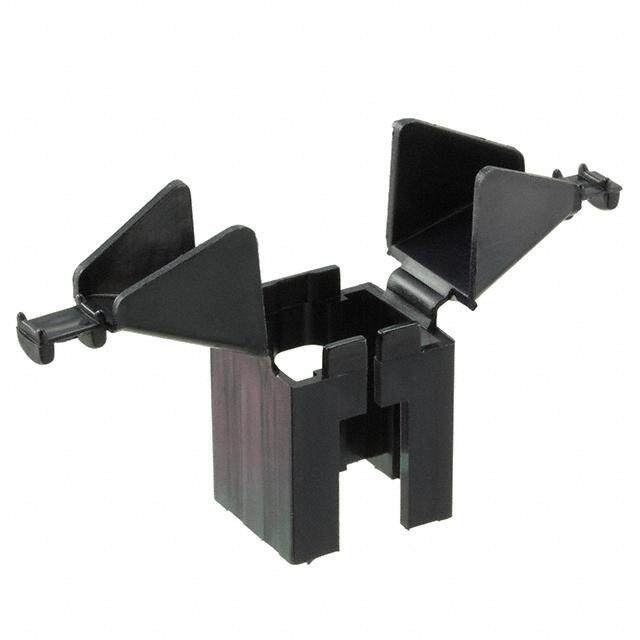
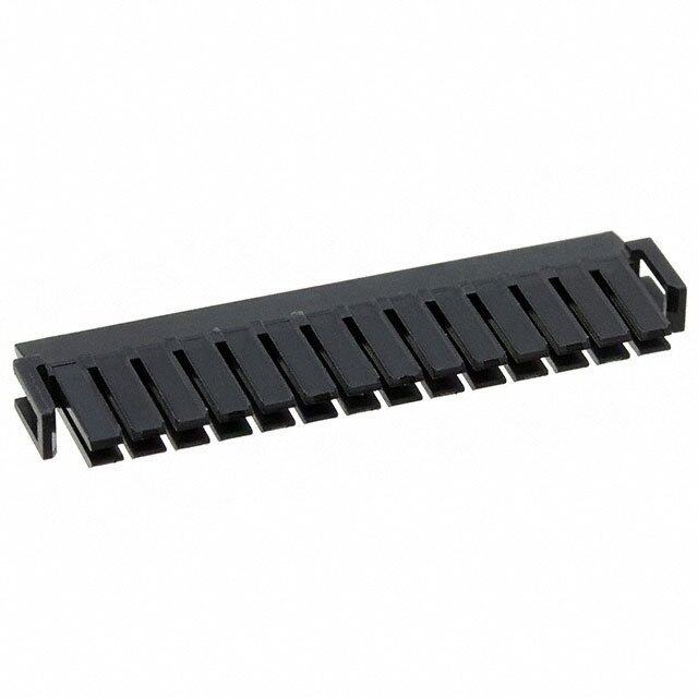
ICGOO在线商城 > 连接器,互连器件 > 矩形连接器 - 配件 > DF19G-14S-1SD-GND
- 型号: DF19G-14S-1SD-GND
- 制造商: Hirose Electric
- 库位|库存: xxxx|xxxx
- 要求:
| 数量阶梯 | 香港交货 | 国内含税 |
| +xxxx | $xxxx | ¥xxxx |
查看当月历史价格
查看今年历史价格
DF19G-14S-1SD-GND产品简介:
ICGOO电子元器件商城为您提供DF19G-14S-1SD-GND由Hirose Electric设计生产,在icgoo商城现货销售,并且可以通过原厂、代理商等渠道进行代购。 DF19G-14S-1SD-GND价格参考。Hirose ElectricDF19G-14S-1SD-GND封装/规格:矩形连接器 - 配件, 。您可以下载DF19G-14S-1SD-GND参考资料、Datasheet数据手册功能说明书,资料中有DF19G-14S-1SD-GND 详细功能的应用电路图电压和使用方法及教程。
| 参数 | 数值 |
| 产品目录 | |
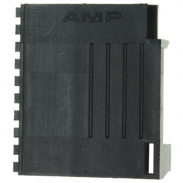
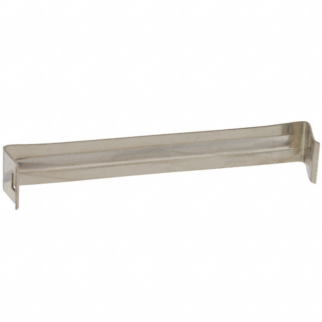
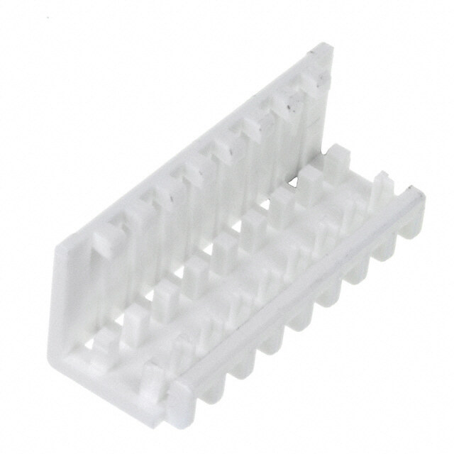
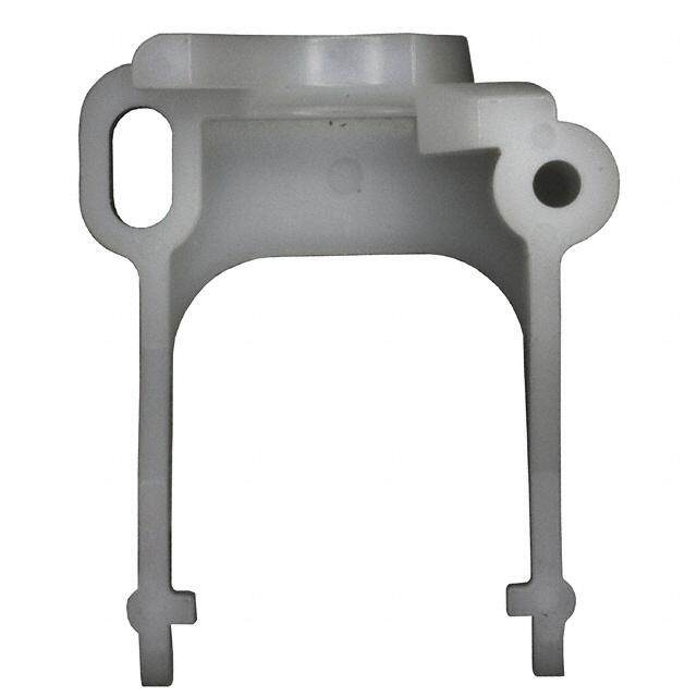
| 描述 | CONN GROUND PLATE COAXIAL 14POS集管和线壳 14P PLUG TOP BRD MNT W/GROUNDING PLATE |
| 产品分类 | |
| 品牌 | Hirose Connector |
| 产品手册 | |
| 产品图片 |
|
| rohs | 符合RoHS无铅 / 符合限制有害物质指令(RoHS)规范要求 |
| 产品系列 | Hirose Connector DF19G-14S-1SD-GNDDF19 |
| 数据手册 | |
| 产品型号 | DF19G-14S-1SD-GND |
| 产品培训模块 | http://www.digikey.cn/PTM/IndividualPTM.page?site=cn&lang=zhs&ptm=24779 |
| 产品目录页面 | |
| 产品种类 | 集管和线壳 |
| 位置数量 | 14 |
| 其它名称 | *DF19G-14S-1SD-GND |
| 商标 | Hirose Connector |
| 安装角 | Vertical |
| 安装风格 | - |
| 工作温度范围 | + 85 C |
| 工厂包装数量 | 100 |
| 标准包装 | 100 |
| 特性 | - |
| 电压额定值 | 100 V |
| 电流额定值 | 300 mA |
| 端接类型 | - |
| 类型 | Ground Plate |
| 系列 | DF19 |
| 节距 | 1 mm |
| 触点材料 | Phosphor Bronze |
| 触点电镀 | Gold |
| 配件类型 | 接地片 |
| 配套使用产品/相关产品 | DF19 连接器 |
| 配用 | /product-detail/zh/DF19G-14S-1SD(05)/H10763-ND/1033342/product-detail/zh/DF19G-14S-1SD/H3115-ND/679741 |
| 针脚数 | 14 |


- 商务部:美国ITC正式对集成电路等产品启动337调查
- 曝三星4nm工艺存在良率问题 高通将骁龙8 Gen1或转产台积电
- 太阳诱电将投资9.5亿元在常州建新厂生产MLCC 预计2023年完工
- 英特尔发布欧洲新工厂建设计划 深化IDM 2.0 战略
- 台积电先进制程称霸业界 有大客户加持明年业绩稳了
- 达到5530亿美元!SIA预计今年全球半导体销售额将创下新高
- 英特尔拟将自动驾驶子公司Mobileye上市 估值或超500亿美元
- 三星加码芯片和SET,合并消费电子和移动部门,撤换高东真等 CEO
- 三星电子宣布重大人事变动 还合并消费电子和移动部门
- 海关总署:前11个月进口集成电路产品价值2.52万亿元 增长14.8%
PDF Datasheet 数据手册内容提取
1mm Contact Pitch, Board-to-Cable, Board-to-FPC, Board-to-Micro-coaxial Cable Connectors DF19 Series Small configuration and board space 8.2 7.2 Cable DF19G-*P-1H(54) 1.5 1.65 Plug DF19A-2830 / 3032 / 36SCFA PCB d. 8.2 e v FPC 7.2 r DF19G-*P-1H(54) e Res (1.7) 1.65 s DF19G-*S-1F(05) PCB ht DF19G-*S-1F-GND(05) g Ri Horizontal mounting All D. 1.5±0.1 (1.7) T Discrete wire FPC L O., ■Overview DF19G-*S-1C(05) Plug C C Industry and market accepted as “De facto” standard for LCD panel 7) 7) RI connections (panels under 12 inches). (7. (7. T High-performance connectors for LVDS high-speed differential DF19-*P-1V(56) Receptacle C signals. E L E (0.78) E ■Features 1.3±0.2 S O Micro-coaxial cable DF19G-*S-1SD(05) R 1.Small configuration and board space +DF19G-*S-1SD-GND HI Thin design accepts discrete wire, thin micro-coaxial cable 8 (Ø1.5mm, Ø1.6mm max.) and FPC 1.7mm maximum thick. 201 2.Common use of receptacle (7.7) ht The same receptacle will accept plugs terminated with discrete wire, DF19-*P-1V(56) g yri FPC or micro-coaxial cable. Vertical mounting p o 3.Uniform external dimensions C 8 The plug assembly external dimensions remain the same when is Top-board mounting Discrete wire 1 terminated with discrete wire, FPC or micro-coaxial cable. 0 1.2 4.Variety of mounting styles c. Device design engineers have a choice of mounting styles : top- e D board, offset, reverse mount offset and vertical. 5.Ground connection Offset mounting Metal grounding plates connect with the common ground line. 6.Glow wire compliance (Compliant with IEC60695-2-11) FPC ■ Applications LCD connections in small consumer devices : digital cameras, Reverse, offset mounting notebook computers, PDA’s. Any device requiring high-density interconnection for consistent high speed transmission data rates. DF19 Micro-coaxial cable Micro-coaxial cable FPC Vertical mounting Twisted pair cable Notebook PC DF19 DF19 DF19 B253
DF19 Series●1mm Contact Pitch, Board-to-Cable, Board-to-FPC, Board-to-Micro-coaxial Cable Connectors ■Product Specifications Current rating 28 AWG : 1A 30 AWG : 0.9A 32 AWG : 0.8A Operating temperature range -35ç to 85ç Note 1 Storage temperature range -10ç to 60ç Note 2 Rating 36 AWG : 0.5A -35ç to 85ç Note 2 FPC : 0.5A Operating humidity range -20% to 80% Storage humidity range -40% to 70% Micro-coaxial cable 40 AWG : 0.3A Voltage rating 100V AC Item Specification Conditions d. e 1.Insulation resistance 500Mø min. 100 V DC v er 2.Withstanding voltage No flashover or insulation breakdown. 300 V AC / one minute s Re 3.Contact resistance 30mø max. (50mø max. for FPC) 100 mA s 4.Insertion-Extraction force ht Min. 0.2N, Max. 3N Measured with a steel pin Ø0.2±0.005 g (per contact) Ri All 5.Vibration No electrical discontinuity of 1μs or more. Frequency : 10 to 55 Hz, single amplitude of 0.75mm, D. 2 hours in each of the 3 directions. T L 6.Humidity Contact resistance : 30mø max. (50mø max. for FPC) 96 hours at temperature of 40±2ç and O., (Steady state) Insulation resistance : 500Mø min. humidity of 90% to 95% C C 7.Temperature cycle Contact resistance : 30mø max. (50mø max. for FPC) Temperature : –55ç➝ +5ç to +35ç➝ +85ç➝+5ç to +35ç RI Insulation resistance : 500Mø min. Time (Minutes) :–30 ➝ +10 ➝ +30 ➝+10 5 cycles T C 8.Durability E Contact resistance : 30mø max. (50mø max. for FPC) 30 cycles (insertion/ withdrawal) L E E 9.Resistance to Re-flow soldering : At the recommended temperature profile S soldering heat No deformation of the insulator parts affecting performance. Manual soldering : Soldering iron temperature 300ç, 3 seconds O R HI Note1 : Includes temperature rise caused by current flow. 8 Note2 : The term “storage” refers to connectors stored for long period of time prior to mounting and use. Operating Temperature 1 0 Range and Humidity range covers non-conducting condition of installed connectors in storage, shipment or during 2 ht transportation. g ri y p o C ■ 8 Materials / Finish 1 0 2 Product Component Material Finish/Color Remarks 1. c. Insulator Polyamide Black or Beige UL94V-0 e D Receptacle Contacts Phosphor bronze Gold plated ---------- Grounding plate Phosphor bronze Tin plated or Tin-copper plated ---------- Insulator Polyamide Beige ---------- Plug Tin-lead plated Stainless steel Tin-copper plated ---------- Crimp contact Contact Phosphor bronze Gold Plated ---------- Insulator Polyamide Beige UL94V-0 Plug for PPC Contact Phosphor bronze Gold plated ---------- Grounding plate for PPC Grounding plate Stainless steel Tin-copper plated ---------- Insulator LCP Beige UL94V-0 Plug for micro-coaxial cable Contact Phosphor bronze Gold plated ---------- Grounding plate Phosphor bronze Tin plated ---------- Grounding plate for micro-coaxial cable Grounding plate Phosphor bronze Tin plated ---------- B254
DF19 Series●1mm Contact Pitch, Board-to-Cable, Board-to-FPC, Board-to-Micro-coaxial Cable Connectors ■ Product Number Structure Refer to the chart below when determining the product specifications from the product number. Please select from the product numbers listed in this catalog when placing orders. ● Connector DF19 # - ** P - 1 H 1 2 3 4 5 6 DF19 # - ** S - 1 F - GND 1 2 3 4 5 6 7 d. e rv 1 Series Name : DF19 3 Number of contacts: 8,14,20,30 (Note 1) e es 2 Configuration 4 Connector type R ■Receptacle S : Plug hts G : Top-board mounting (1.65mm high) P : Receptacle g K : Offset mounting (1.0mm high) 5 Contact pitch : 1mm Ri All LKR:: ROeffvseerts me oouffnsteint gm (o1u.1nmtinmg hviegrhs)ion of 6 MHount:i nHgo rtyizpoen/tTael rSmMinTation type D. DF19K (1.0mm high) V : Vertical SMT T O., L ■BPllaungk fo:r Ndois cgrreotuen wdiinreg plate CF :: PPlluugg –– dFiPscCrete wire (crimp contact) C SD : Plug – micro-coaxial cable C G : With grounding plate 7 Additional separate component RI ■Plug for FPC GND : Ground plate (Note 2) T C G : With grounding plate E L ■Grounding plate for FPC E E G : With grounding plate S O ■Plug for micro-coaxial cable R G : With grounding plate HI 8 ■Grounding plate for micro-coaxial cable 1 0 G : With grounding plate 2 ht Note 1 : Number of contacts will differ depending on the connector style. g Note 2 : Grounding plates are required when terminating with the FPC and micro-coaxial cable. ri y p o C 8 1 0 ●Contact 2 1. DF19A - 2830 SCF A (** **) c. e D 1 2 3 4 1 Conductor size 3 Plating 2830 : 28 to 30 AWG A : Gold 3032 : 30 to 32 AWG 0036 : 36 AWG 2 Contact type 4 Packaging SCF : Plug contact, tape and reel Blank: 10,000 pcs/reel packaging (41) : 20,000 pcs/reel B255
DF19 Series●1mm Contact Pitch, Board-to-Cable, Board-to-FPC, Board-to-Micro-coaxial Cable Connectors ■Right angle receptacle, top-board mounting A 2.375 B 2.175 P=1 0.25 5 4 2. 7 4. d. e v 2 Contact No. 1 indicator r se C e R 65 5.7 65 s 1. 1. ht g Ri All D. T L O., C BPCB mounting pattern C RI T C E L E 1.85±0.1 B±0.05 1.65±0.1 E OS +0.11 0 P=1±0.05 0.55±0.05 R HI 8 1 0 2 ht g 5 yri 0.0 p ± o 5 C 2. 18 +0.12.5 0 1.1+ 00.1 Outline of the receptacle No conductive traces 0 2 1. c. e D Specification (54) : Tape & reel packaging (1,000 pcs/reel) Unit : mm Part No. HRS No. No. of contacts A B C Remarks RoHS DF19G-18P-1H (54) 685-0021-0 54 8 11.55 7 11.95 DF19G-14P-1H (54) 685-0004-0 54 14 17.55 13 17.95 1.65mm high YES DF19G-20P-1H (54) 685-0006-6 54 20 23.55 19 23.95 DF19G-30P-1H (54) 685-0015-7 54 30 33.55 29 33.95 Note : Order by number of reels. B256
DF19 Series●1mm Contact Pitch, Board-to-Cable, Board-to-FPC, Board-to-Micro-coaxial Cable Connectors ■Right angle receptacle, offset mounting A 2.375 B 2.175 P=1 0.25 5 4 2. 7 DF19K 4. identification indicator d. e v 2 Contact No. 1 indicator er 1 s C Re 46F 6.7 F s 1. ht g Ri All D. T L O., C BPCB mounting pattern C RI T 3.175±0.1 B±0.05 2.975±0.1 C E P=1±0.05 L OSE E +0.11.5 0 0.55±0.05 1+ 00.1 R HI 0.3 8 1 0 2 1 ht ±0. 1 yrig 5.5 3±0. Cop 0.3 5. 18 +0.15 0 Outline of the receptacle 0 2. 2 1. Dec. Outline of the plug D+-00..12 2.2) ( E±0.1 Specification (54) : Tape & reel packaging (1,000 pcs/reel) Unit : mm Part No. HRS No. No. of contacts A B C D E F Remarks RoHS DF19K-20P-1H (54) 685-0008-1 54 20 23.55 19 26.55 24.15 25.15 0.1 1.0mm high YES DF19K-30P-1H (54) 685-0032-6 54 30 33.55 29 36.55 34.15 35.15 0.1 Part No. HRS No. No. of contacts A B C D E F Remarks RoHS DF19L-14P-1H (54) 685-0003-8 54 14 17.55 13 20.55 18.15 19.15 1.1 DF19L-20P-1H (54) 685-0019-8 54 20 23.55 19 26.55 24.15 25.15 1.1 1.1mm high YES DF19L-30P-1H (54) 685-0016-0 54 30 33.55 29 36.55 34.15 35.15 1.1 Note : Order by number of reels. B257
DF19 Series●1mm Contact Pitch, Board-to-Cable, Board-to-FPC, Board-to-Micro-coaxial Cable Connectors ■ Right angle receptacle, reverse offset mounting A 2.375 B 2.175 P=1 0.25 5 4 2. 7 4. d. 2 e rv 1 Contact No. 1 indicator e C s e 6 6.7 s R 1.4 1 1 ht g Ri All D. T L O., C BPCB mounting pattern C RI T C E L 3.175±0.1 B±0.05 2.975±0.1 E E P=1±0.05 S RO +0.15 0 0.55±0.05 1+ 00.1 HI 1. 8 3 01 0. 2 ht pyrig ±0.1 +0.12.5 0 0.1 Co 5.5 5.3± 8 1 0 2 c.1. Outline of the receptacle 0.3 (2.2) e D Outline of the plug D+-00..12 E±0.1 Specification (54) : Tape & reel packaging (1,000 pcs/reel) Unit : mm Part No. HRS No. No. of contacts A B C D E Remarks RoHS DF19KR-14P-1H (54) 685-0024-8 54 14 17.55 13 20.55 18.15 19.15 1.0mm high YES DF19KR-20P-1H (54) 685-0023-5 54 20 23.55 19 26.55 24.15 25.15 Note : Order by number of reels. B258
DF19 Series●1mm Contact Pitch, Board-to-Cable, Board-to-FPC, Board-to-Micro-coaxial Cable Connectors ■ Vertical receptacle 7 0 1. 2 P=1 0.25 1 1. 0.95 B 1.3 A 1.56 2 2 d. 5. e v 1.96 r Contact No. 1 indicator se C 1 3.8 e R s ht A g Ri 2 25 All 0. D. T L O., C BPCB mounting pattern C RI T C E L E E 1.5++00.1 D±0.05 S O Outline of the plus 018 HIR +0.11.45+0 65±0.05 2.5+00.1 +0.10.650 2±0.05 2 0. 2. ht g ri y p Co 05 8 ±0. 01 1.46 P=1±0.05 0.55±0.05 2 Dec.1. (E) (F) +0.11.7+0 0.8±0.05 G±0.05 Specification Conductive traces in this area must be covered by dielectric compound. (56) : Tape & reel packaging (1,000 pcs/reel) Unit : mm Part No. HRS No. No. of contacts A B C D E F G RoHS DF19-14P-1V (56) 685-0036-7 56 14 17.9 13 15.25 14.95 6.675 6.325 13 YES DF19-20P-1V (56) 685-0037-0 56 20 23.9 19 21.25 20.95 9.675 9.325 19 Note : Order by number of reels. B259
DF19 Series●1mm Contact Pitch, Board-to-Cable, Board-to-FPC, Board-to-Micro-coaxial Cable Connectors ■Plug (Discrete wire) DF19-*S-1C DF19G-*S-1C(05) A A B B P=1 P=1 6.1 6.1 Contact No. 5 and multiples indicator Contact No. 5 and multiples indicator Contact No. 1 indicator Contact No. 1 indicator 5 5 1. 1. A A d. Contact No. 1 indicator e v No. of contacts 41 er indicator s e R s Shown with terminated and installed contacts ht Specification g Ri Blank,(05) : Bag packaging All (100 pcs/pack) D. Unit : mm T L Part No. HRS No. No. of contacts A B RoHS Part No. HRS No. No. of contacts A B RoHS O., DF19 -18S-1C 685-0029-1 8 11.5 7 DF19G -18S-1C(05) 685-0022-2 05 8 11.5 7 C C DF19 -14S-1C 685-0012-9 14 17.5 13 YES DF19G -14S-1C(05) 685-0005-3 05 14 17.5 13 YES RI DF19 -20S-1C 685-0011-6 20 23.5 19 DF19G -20S-1C(05) 685-0007-9 05 20 23.5 19 T C DF19 -30S-1C 685-0013-1 30 33.5 29 DF19G -30S-1C(05) 685-0014-4 05 30 33.5 29 E L Note: Order by number of bags. E SE ■Crimp contacts O R HI Part No. HRS No. Packaging Quantity Finish RoHS 8 DF19A-2830SCFA (* *) 685-0048-6 ** 1 20 DF19A-3032SCFA (* *) 685-0046-0 ** Tape & reel See Specifications Gold plated YES 0.7 0.63 ht DF19A-3336SCFA (* *) 685-0047-3 ** number below g ri y p Specification number * *(* *) o C Blank: Tape & reel packaging (10,000 pcs/reel) 8 (41) : Tape & reel packaging (20,000 pcs/reel) 1 20 ●Applicable cable (Tin plated annealed conductor) 5.1 0.9 1. c. Wire size (stranded wire conductor) Jacket diameter e 2 D 28 AWG (7/ 0.127mm) 30 AWG (7/ 0.1mm) 0.5mm to 0.6mm 5 0. 32 AWG (7/ 0.08mm) 36 AWG (7/ 0.05mm) 0.27mm Carrier strip ●Applicable UL style ●Strip length ●UL1571(thin type) (Note2) ●1.2mm to 1.9mm t=0.15 Note 1 : When using other than the recommended wire, contact your Hirose sales representative. Note 2 : Contact your Hirose sales representative when using 36 AWG. ●Tools Part Part No. HRS No. Applicator AP105-DF19S 901-4571-3 Press unit CM-105C 901-0001-0 Note 1 : Use of other than Hirose Electric approved tools will void the product warranties. Note 2 : Contact Hirose for the wire striping, contact crimp and contact insertion instructions. Note 3 : Please do the crimping operations according to the "Crimping quality standard" and "Crimping condition table". B260
DF19 Series●1mm Contact Pitch, Board-to-Cable, Board-to-FPC, Board-to-Micro-coaxial Cable Connectors ■Plug (Flat Printed Circuit) Note: Socket and grounding plate is required. A B C P=1 5.95 A 1.2 CAV No. d. ve Shown terminated with FPC Polarizing mark indicator r e s e D±0.08 R 0.45±0.3 s 0.3±0.15 C±0.05 5 t=0.145±0.03 CO., LTD. All Right M0.35±0.25ARXR00.M.2AX2R0 .2 00..4EP3±0=±5.170±0±±..00000.5.5.000333 (0.35)1.85±0.22±0.15 3.600..2.2±0.0500550.2±0.15RR00.0.2±0.1.12±0.05 0.3±0.1G5round area < :1 to 5μm thick solder plated> C Signal area < :1 to 5μm thick solder plated> RI Unit : mm T C Part No. HRS No. No. of contacts A B C D E RoHS Specification E EL DF19G-14S-1F(05) 685-0017-2 05 14 17.5 17.1 13 15.6 14 (05) : (B1a0g0 ppaccsk/paagcinkg) E DF19G-20S-1F(05) 685-0009-4 05 20 23.5 23.1 19 21.6 20 YES S O DF19G-30S-1F(05) 685-0033-9 05 30 33.5 33.1 29 31.6 30 R HI Note : Order by number of bags. 8 1 0 ■Ground plate for FPC 2 A ht B g ri Contact No. 1 indicator y No. of contacts indicator p o 1 C 4. SIGNAL 14 8 1.5 1 C 0 2 D 1. c. e D Unit : mm Part No. HRS No. No. of contacts A B C D RoHS Specification (05) : Bag packaging DF19G-14S-1F-GND(05) 685-0018-5 05 14 15.75 14.35 17.5 14.4 (100 pcs/pack) DF19G-20S-1F-GND(05) 685-0010-3 05 20 21.75 20.35 23.5 20.4 YES DF19G-30S-1F-GND(05) 685-0034-1 05 30 31.75 30.35 33.5 30.4 Note : Order by number of bags. ●Grounding plate installation tools Type Part No. HRS No. Desktop tool (for 14 pos.) DF19G-14S/PR-MD2 902-4514-6 Desktop tool (for 20 pos.) DF19G-20S/PR-MD2 902-4513-3 Desktop tool (for 30 pos.) DF19G-30S/PR-MD2 902-4518-7 Note1 : Product is not guaranteed unless Hirose approved tools are used. B261
DF19 Series●1mm Contact Pitch, Board-to-Cable, Board-to-FPC, Board-to-Micro-coaxial Cable Connectors ■Plug (Micro-coaxial cable) N C±0.2 MI A D±0.15 1.2 B P=1±0.1 at P=1 X Inner conductor co Contact No. 1 indicator MA Insulator der 10.9 Grounding bar Sol 1 0. 6. 3± 1.33 0.05 Outer conductor 0.55-00.05 ± Jacket 7 0. Cable preparation d. e v r e s e R s Note 1 : Connectors are designed to allow termination without cutting ght Shown terminated with micro-coaxial cable of the pitch loss prevention tape. Ri Note 2 : Required Solder coating for inner conductor. All Note 3 : When using 2-conductor micro-coaxial cable some contact D. positions will not be used. T L Contact your Hirose sales representative. O., Part No. HRS No. No. of contacts A B C D RoHS C Specification C DF19G-14S-1SD(05) 685-0026-3 05 14 17.4 13 14.8 13 RI DF19G-20S-1SD(05) 685-0025-0 05 20 23.4 19 20.8 19 YES (05) : (B1a0g0 ppaccsk/paagcinkg) T C E Note : Order by number of bags. L E E ●Applicable cable (Micro-coaxial cable) S O R Wire size (stranded wire center conductor) Jacket diameter HI 8 40 AWG (7/ 0.03mm) 0.3mm to 0.4mm 1 0 ht 2 ■Grounding plate for micro-coaxial cable g ri y p o C 18 4.36 0 2 1. Contact No. 1 indicator c. e A D 7 2 1. Specification Blank: Bag packaging (100 pcs/pack) Unit : mm Part No. HRS No. No. of contacts A RoHS DF19G-14S-1SD-GND 685-0028-9 14 17.5 YES DF19G-20S-1SD-GND 685-0027-6 20 23.5 B262
DF19 Series●1mm Contact Pitch, Board-to-Cable, Board-to-FPC, Board-to-Micro-coaxial Cable Connectors BEmbossed Carrier Tape Dimensions Receptacles ●DF19G-*P-1H(54) 0.1 G-G ●●DDFF1199KL--**PP--11HH((5544)) Ø1.5 +00.1 2±0.1142±±00.1.1 G1.75± 1t=.705.3±±0±.105.1 2±0.5 Part number label Depth of 1.5 diameter 1 ±0. Ø13 C0.10.3 0.3 Ø80 330 ±± ± Ø BA D 1 H H Ø2 E+ 20 F 2.5±0.15 G d. H-H Unreeling direction e v ser 2.3) 7.8±0.3 Unit : mm e ( R Connector No. of contacts A B C D E F Remarks s ht DF19G-18P-1H(54) 08 24 -------- 11.5 16.1 24.4 30.4 g Ri DF19G-14P-1H(54) 14 44 40.4 20.2 22.1 44.4 50.4 Top-board mounting All DF19G-20P-1H(54) 20 44 40.4 20.2 28.1 44.4 50.4 (1.65mm high) D. DF19G-30P-1H(54) 30 56 50.2 26.2 38.1 56.4 62.4 T O., L DDFF1199KK--2300PP--11HH((5544)) 2300 4546 4502..44 2206..22 2388..11 4546..44 5602..44 O(1ff.s0emt mm ohuignhti)ng C C DF19L-14P-1H(54) 14 44 40.4 20.2 22.1 44.4 50.4 RI Offset mounting DF19L-20P-1H(54) 20 44 40.4 20.2 28.1 44.4 50.4 T (1.1mm high) C DF19L-30P-1H(54) 30 56 52.4 26.2 38.1 56.4 62.4 E L OSE E ●DF19KR-*P-1H(54) Ø1.5 +00.1 12±0.1 G 1.75±0.1 G-G1t=.705.3±±00.1.15 R HI 2±0.5 8 0.1 Part number label Ø1.5 in the rear 1 ± ght 20 CB±0.1A±0.3 D±0.3 Ø13 Ø80Ø330 ri y H op H 21 8 C 2.85±0.15 UnreeGling direction Ø E+ 02F 1 H-H 0 2 c.1. (2.3) 7.8±0.3 Unit : mm e D Connector No. of contacts A B C D E F Remarks DF19KR-14P-1H(54) 14 44 40.4 20.2 22.1 44.4 50.4 Reverse type of DF19K DF19KR-20P-1H(54) 20 44 40.4 20.2 28.1 44.4 50.4 Offset mounting (1.0mm high) 1 ●DF19-*P-1V(56) Ø1.5+0+0.1 2±0.1 12±0.1 4±0.11.75±0. G 3.7±0.2 4±0.2 C±0.1B±0.1A±0.3 D±0.2Part num2be±r 0la.b5el ØDd1i3eapmthe toefr 1.Ø805 380±2 Ø H H G Ø21 E++20 t=0.4±0.1 F Unreeling direction Unit : mm Connector No. of contacts A B C D E F Remarks DF19-14P-1V(56) 14 32 28.4 14.2 18.2 32.4 38.4 Vertical receptacle DF19-20P-1H(56) 20 44 40.4 20.2 24.2 44.4 50.4 B263
DF19 Series●1mm Contact Pitch, Board-to-Cable, Board-to-FPC, Board-to-Micro-coaxial Cable Connectors BUse recommendations 1. Recommendedtemperature profile Temperature(ç) 250ç 220 200ç 180 150ç Preheating soldering 60 to 120(S) 250ç 10(s)max d. 220ç min 60(s)max e 100ç v r e s e 50ç R s ht g Ri All 30 50 100 150 200 TIME(S) D. T Note 1 : Up to 2 cycles of Reflow soldering are possible under the same L O., conditions, provided that there is a return to normal temperature between the first and second cycle. C C Note 2 : The temperature profile indicates the board surface temperature at RI the point of contacts with the connector terminals. T C Note 3 : The product can be used without trouble though the surface of a E L grounding plate might discolor. E E S O 2. Manual soldering Manual soldering : 290±10ç for 3 seconds R HI 3. Screen thickness 0.15mm 8 4. Board warpage Maximum of 0.03mm at the connector center, with both ends of the connector as 1 0 reference points. 2 ht 5. Cleaning conditions Refer to “Wire-to-Board Connector Use Handbook.” g yri 6. Termination conditions Refer to “Wire-to-Board Connector Use Handbook.” p o 7. Cautions ■Do not twist when mating/un-mating. C 8 8. Precautions Refer to “Wire-to-Board Connector Use Handbook.” 1 0 2 1. c. e D B264
DF19 Series●1mm Contact Pitch, Board-to-Cable, Board-to-FPC, Board-to-Micro-coaxial Cable Connectors BPlug (FPC Type) Termination Procedures (Dedicated Assembly Tooling is required.) Insert the FPC diagonally from the top surface of the grounding plate. Step 1 Pass the FPC through the grounding plate. After passing through, lower the FPC (as shown) to horizontal position. Signal surface Step 2 Ground surface d. Extend the FPC out and fully insert into the socket. e v r Step 3 e s e Exercising caution slide the grounding plate forward and pre-insert it over the socket. R hts Step 4 g Ri Assembly point: Slightly raise the FPC to an angle of about 30 degrees, All and then insert the grounding plate over the socket. D. T Using the dedicated installation tool, insert the grounding plate. L O., Final C completion RIC 1.7 T C Note 1 : The grounding plate and the plug are supplied as separate components. E L Note 2 : Dedicated assembly fixtures are required at each stage of the termination process. For detail, refer to the instruction manual E E supplied with the tools. S O Note 3 :Do not apply excessive forces to FPC (Bending or twisting) as it may introduce cracks in the copper foil (on the cover film edge). R Note 4 : To protect the FPC, insertion and disconnection of the connectors should be performed parallel to the mating direction. HI Note 5 : Do not apply excessive tension to FPC. 8 1 Note 6 : Refer to FPC manufacturer for bend radius and other specific recommendation. Distance should be allowed for the bending 0 2 position, as illustrated below. ht g ri y p o C 8 1 0 2 1. ec. SIGNAL D 10 N 5 N MI MI Note 7 : Follow the instruction manuals for the termination and assembly fixtures and tools. B265 Powered by TCPDF (www.tcpdf.org)
Mouser Electronics Authorized Distributor Click to View Pricing, Inventory, Delivery & Lifecycle Information: H irose Electric: DF19-2830SCFA DF19-2830SCFA(41) DF19-3032SCFA DF19-3032SCFA(41) DF19G-20S-1F(09) DF19L-30P- 1H(56) DF19M-14P-1H(56) DF19KR-20P-1H(55) DF19K-30P-1H(56) DF19G-30S-1F(09) DF19GA-20S-1SD(05) DF19G-20S-1FH(05) DF19G-20S-1FH-GND(05) HT302/DF19S DF19KR-14P-1H(54) DF19G-14S/PR-MD DF19G- 20S/PR-MD DF19G-20S/PR-MD2 DF19G-30S/PR-MD2 DF19G-14S/PR-MD2 AP105-DF19S(65) DF19G-20P-1H(55) AP105-DF19S(62) AP105-DF19S(63) AP105-DF19S(70) AP105-DF19S(61) DF19K-8P-1H(54) AP105-DF19S(66) AP105-DF19S(01) DF19G-8P-1H(55) DF19LA-20P-1H(54) DF19G-30P-1H(55) AP105-DF19S(64) DF19G-14P- 1H(55) AP105-DF19S HT302/DF19S(62) HT302/DF19S(64) HT302/DF19S(61) HT302/DF19S(63) AP109A-DF19S- 36S(63) AP109A-DF19S-36S(61) AP109A-DF19S-36S(62) AP105-DF19S-36S

 Datasheet下载

