ICGOO在线商城 > 连接器,互连器件 > 矩形连接器 - 针座,公插针 > DF13-8P-1.25DSA
- 型号: DF13-8P-1.25DSA
- 制造商: Hirose Electric
- 库位|库存: xxxx|xxxx
- 要求:
| 数量阶梯 | 香港交货 | 国内含税 |
| +xxxx | $xxxx | ¥xxxx |
查看当月历史价格
查看今年历史价格
DF13-8P-1.25DSA产品简介:
ICGOO电子元器件商城为您提供DF13-8P-1.25DSA由Hirose Electric设计生产,在icgoo商城现货销售,并且可以通过原厂、代理商等渠道进行代购。 DF13-8P-1.25DSA价格参考¥2.19-¥5.23。Hirose ElectricDF13-8P-1.25DSA封装/规格:矩形连接器 - 针座,公插针, 8 位 接头 连接器 0.049"(1.25mm) 通孔 锡。您可以下载DF13-8P-1.25DSA参考资料、Datasheet数据手册功能说明书,资料中有DF13-8P-1.25DSA 详细功能的应用电路图电压和使用方法及教程。
| 参数 | 数值 |
| 产品目录 | |
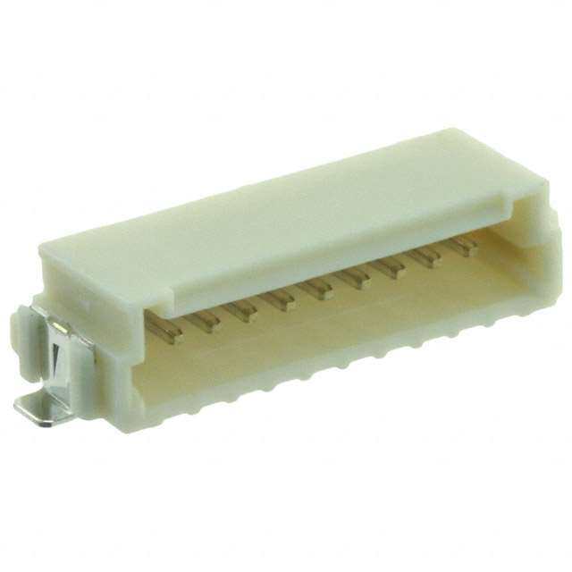
| 描述 | CONN HEADER 8POS 1.25MM STR TIN集管和线壳 1.25MM V PCB HEADER 8P THRU-HOLE TIN |
| 产品分类 | |
| 品牌 | Hirose Connector |
| 产品手册 | |
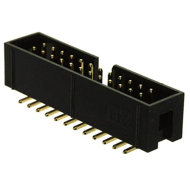
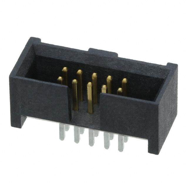
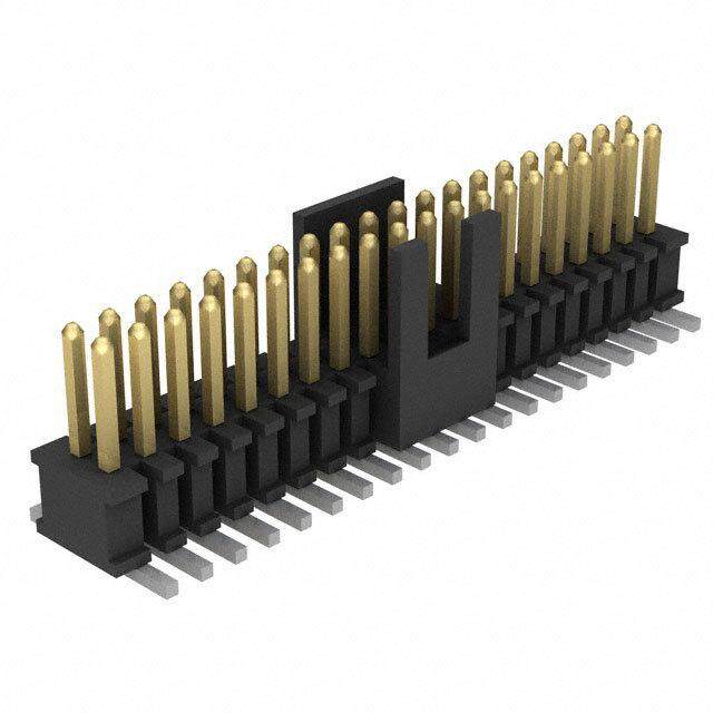
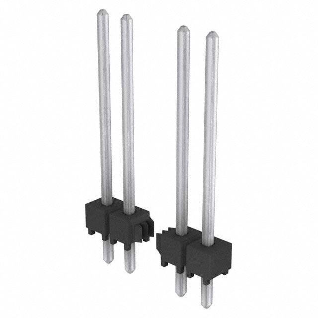
| 产品图片 |
|
| rohs | 符合RoHS无铅 / 符合限制有害物质指令(RoHS)规范要求 |
| 产品系列 | Hirose Connector DF13-8P-1.25DSADF13 |
| 数据手册 | |
| 产品型号 | DF13-8P-1.25DSA |
| 产品培训模块 | http://www.digikey.cn/PTM/IndividualPTM.page?site=cn&lang=zhs&ptm=24779 |
| 产品目录绘图 |
|
| 产品目录页面 | |
| 产品种类 | 集管和线壳 |
| 产品类型 | Headers |
| 位置数量 | 8 |
| 其它名称 | *DF13-8P-1.25DSA |
| 加载的针脚数 | 全部 |
| 包装 | 散装 |
| 商标 | Hirose Connector |
| 外壳材料 | Polyamide |
| 安装类型 | 通孔 |
| 安装风格 | - |
| 工厂包装数量 | 100 |
| 排数 | 1 |
| 排距 | - |
| 标准包装 | 100 |
| 特性 | 板导轨 |
| 特色产品 | http://www.digikey.cn/product-highlights/zh/df13-series/51027 |
| 电压额定值 | 150 V |
| 电流额定值 | 1 A |
| 端接 | |
| 端接类型 | Through Hole |
| 类型 | Shrouded |
| 系列 | DF13 |
| 紧固类型 | - |
| 节距 | 1.25 mm |
| 触头类型 | 公形引脚 |
| 触头配接长度 | - |
| 触头镀层 | 锡 |
| 触头镀层厚度 | - |
| 触点材料 | Brass |
| 触点电镀 | Tin |
| 触点类型 | Pin (Male) |
| 连接器类型 | 接头,有罩 |
| 配套产品 | /product-detail/zh/DF13-8S-1.25C/H2185-ND/241755 |
| 针脚数 | 8 |
| 间距 | 0.049"(1.25mm) |
| 颜色 | 浅褐 |

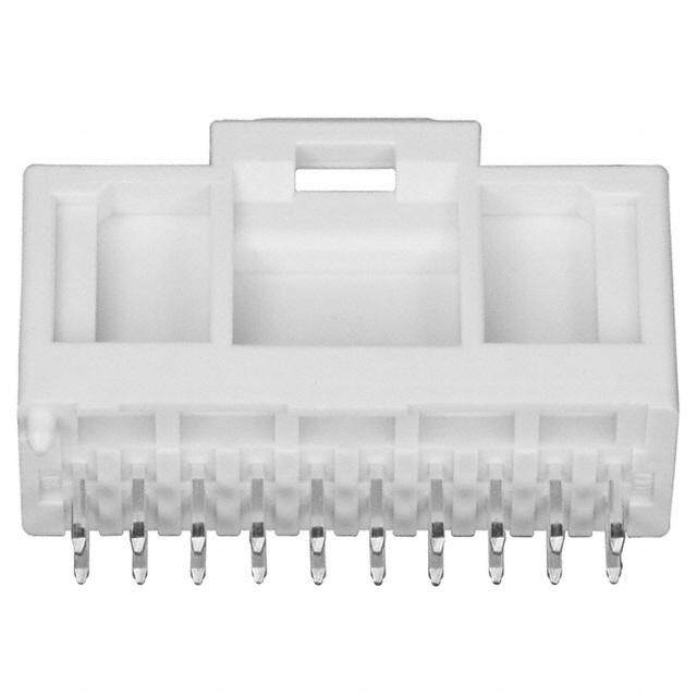

- 商务部:美国ITC正式对集成电路等产品启动337调查
- 曝三星4nm工艺存在良率问题 高通将骁龙8 Gen1或转产台积电
- 太阳诱电将投资9.5亿元在常州建新厂生产MLCC 预计2023年完工
- 英特尔发布欧洲新工厂建设计划 深化IDM 2.0 战略
- 台积电先进制程称霸业界 有大客户加持明年业绩稳了
- 达到5530亿美元!SIA预计今年全球半导体销售额将创下新高
- 英特尔拟将自动驾驶子公司Mobileye上市 估值或超500亿美元
- 三星加码芯片和SET,合并消费电子和移动部门,撤换高东真等 CEO
- 三星电子宣布重大人事变动 还合并消费电子和移动部门
- 海关总署:前11个月进口集成电路产品价值2.52万亿元 增长14.8%


PDF Datasheet 数据手册内容提取
1.25mm Pitch Miniature Crimping Connector (UL Listed) DF13 Series Type Mounting Type Mounting Height(h) e DIP 5.3mm p y T ht g ai ed. Str SMT 5.8mm v r e s e R hts Type DIP g Ri gle 3.6mm All An D. ght SMT T Ri L O., C C RI ■Features T Correspond to Automatic Mounting C E 1. Miniature Size Secure the automatic plain area for the absorption L type automatic mounting machine. E Designed in the low profile at mounting height 5.8mm. E (SMT mounting straight type) S O (For DIP type, the mounting height is to 5.3mm to the R Straight Type Absorption area HI straight and 3.6mm at the right angle) 8 2. Multi-contact 1 0 The double row type achieves the multi-contact up to 40 2 ht contacts, and secures 30% higher density in the mounting g area, compared with the single row type. ri y p 3. Correspond to Automatic Mounting o C The header provides the grade with the vacuum absorption 8 area, and secures automatic mounting by the embossed 1 0 tape packaging. 2 1. In addition, the tube packaging can be selected. (Fig.1) c. e 4. Integral Basic Function Despite Miniature Size D Metal fitting The header is designed in a scoop-proof box structure, and Right Angle Type completely prevents mis-insertion. Absorption area In addition, the surface mounting (SMT) header is equipped with the metal fitting to prevent solder peeling. (Fig.1) 5. UL Certifled ■Applications Note PC, mobile terminal, miniature type business equipment, and other various consumer equipment, including video camera Fig.1 B242
DF13 Series●1.25mm Pitch Miniature Crimping Connector (UL Listed) ■Product Specifications Specification Current rating 1A UL Operating Temperature Range : -35to +85ç (Note 1) Storage Temperature Range : -10to +60ç (Note 2) Rating Specification AC 150V Operating Moisture Range : 20to 80% (Note 3) Storage Moisture Range : 40to 70% (Note 2) Voltage rating UL AC/DC 29.9V Item Specification Condition 1.Insulation Resistance 500Mø min. 100V DC 2.Withstanding voltage No flashover or insulation breakdown. 500V AC/1 minute 3.Contact Resistance 30mø max. 100mA 4.Single Insertion/Extraction Force 0.3N (30gf) min., 3N (300gf) max. Measured at the square steel pin of 0.35±0.002mm d. 5.Vibration No electrical discontinuity of 1μs or more Frequency : 10 to 55 Hz, single amplitude of 0.75 mm, 2 hours in each of the 3 directions. e v 6.Humidity (Steady state) Contact resistance : 30mø max. Insulation resistance: 500Mø min. 96 hours at temperature of 40ç and humidity of 90% to 95% r e s 7.Temperature Cycle Contact resistance : 30mø max. Insulation resistance : 500Mø min. (-55ç : 30 minutes➝5to 35ç : 10 minutes➝85ç : 30 minutes➝5to 35ç : 10 minutes) 5 cycles e R 8.Durability (Mating/un-mating) Contact resistance : 30mø max. Tin plating : 30 cycles s ht Gold plating : 50 cycles g Ri 9.Resistance to Soldering heat No deformation of components affecting performance. Flow : 250ç for 10 seconds All Manual soldering : 300ç for 3 seconds D. Reflow : At the recommended temperature profile T O., L Note 1 : Includes temperature rise caused by current flow. Manual soldering● :U 30L0 çFi floer N3 soe.c aonndds Recognition C C Note 2 : OThpee rtaetrimng " sTteomrapgeer"a rtuerfeer Rs aton gpero adnudc tHs usmtoirdeitdy froarn lgoen gc opveerirosd n oofn t icmoen dpuricotrin tgo cmoonudnittiionng oafnd use. No. UL : E52653 RI installed connectors in storage, shipment or during transportation. T Note 3 : Use without condensation on parts. C E L ■Materials/Finish E E S Product Part Material Finish Remarks O R Crimping Socket Insulator Polyamide Beige UL94V-0 HI Crimping Contact for Socket Contact Phosphor copper Tin plated or gold plated ---- 8 Insulator Polyamide Beige UL94V-0 01 Pin Header (Through hole) Contact Brass Tin plated ---- 2 ht Insulator Polyamide Beige UL94V-0 g Pin Header (SMT Single row) Contact Brass Tin plated or gold plated ---- ri y Metal Fitting Phosphor copper Tin plated ---- p o Insulator Polyamide Beige UL94V-0 C 8 Pin Header (SMT Double row) Contact Brass Tin-copper plated or gold plated ---- 1 Metal Fitting Phosphor copper Tin plated ---- 0 2 ■ 1. Product Number Structure c. e Refer to the chart below when determining the product specifications from the product number. D Please select from the product numbers listed in this catalog when placing orders. ●Connector DF13 # - * S - 1.25 C q w e r t y qSeries Name : DF13 eNumber of Contacts tContact Pitch: 1.25mm wStyle Symbol : Blank : With boss rSingle row : 2to 12, 14, 15 yConnection Form / Contact Style. (A : Without boss rDouble row : 10, 20, 30, 40 C : Crimping socket / DSA : Straight through hole C : Without boss rConnector Type DS : Right angle through hole / V : Straight SMT tS : Single row socket / P : Single row pin header H : Right angle SMT tDS : Double row socket / DP : Double row pin header ●Contact DF13 # - 2630 SCF A qStyle Symbol Blank: Standard ePackaging Type SCF : Socket Contact/Reel G: Low insertion / extraction rPlating Type Blank : Tin plated q w e r wApplicable Cable Size 2630 : 26to 30 AWG A : Gold plated 3032 : 30to 32 AWG B243
DF13 Series●1.25mm Pitch Miniature Crimping Connector (UL Listed) ■Single Row Socket d. e v r e s e R Photo: Contact insertion s ht g Ri All D. T L Unit : mm O., Part No. HRS No. No. of Contacts A B RoHS Part No. HRS No. No. of Contacts A B RoHS C DF13-2S-1.25C 536-0001-4 2 1.25 4.15 DF13- 9S-1.25C 536-0008-3 9 10.00 12.90 C DF13-3S-1.25C 536-0002-7 3 2.50 5.40 DF13-10S-1.25C 536-0009-6 10 11.25 14.15 RI DF13-4S-1.25C 536-0003-0 4 3.75 6.65 DF13-11S-1.25C 536-0010-5 11 12.50 15.40 T C DF13-5S-1.25C 536-0004-2 5 5.00 7.90 Yes DF13-12S-1.25C 536-0011-8 12 13.75 16.65 Yes E L DF13-6S-1.25C 536-0005-5 6 6.25 9.15 DF13-13S-1.25C 536-0012-0 13 15.00 17.90 E DF13-7S-1.25C 536-0006-8 7 7.50 10.40 DF13-14S-1.25C 536-0013-3 14 16.25 19.15 E S DF13-8S-1.25C 536-0007-0 8 8.75 11.65 DF13-15S-1.25C 536-0014-6 15 17.50 20.40 O Note 1 : The quantity is delivered per bag (100 pcs.). If needed, please select and order the products per bag. R HI 8 1 ■Double Row Socket 0 2 ht g ri y p o C 8 1 0 2 1. c. e D Photo: Contact insertion state Unit : mm Part No. HRS No. No. of Contacts A B RoHS DF13-10DS-1.25C 536-0550-2 10 10.40 5.00 DF13-20DS-1.25C 536-0555-6 20 16.65 11.25 Yes DF13-30DS-1.25C 536-0560-6 30 22.90 17.50 DF13-40DS-1.25C 536-0565-0 40 29.15 23.75 Note : The quantity is delivered per bag (100pcs). If needed, please select and order the products per bag. B244
DF13 Series●1.25mm Pitch Miniature Crimping Connector (UL Listed) ■Single Row Straight Pin Header (Through hole) [Specific No.] (**), ** Blank : Tin plated (75) : Tin plated, tube packaging BTube Dimensions 5 d. e v r e s 0 e 1 R ●Board Through-hole Diameter:Ø0.6±0.03 s ht g Ri All D. Unit: mm T L Part No. HRS No. No. of Contacts A B Tube Packaging Quantity RoHS Part No. HRS No. No. of Contacts A B Tube Packaging Quantity RoHS O., DF13-2P-1.25DSA(**) 536-0101-9 ** 2 1.25 4.15 115 DF13- 9P-1.25DSA(**) 536-0108-8 ** 9 10.00 12.90 37 C DF13-3P-1.25DSA(**) 536-0102-1 ** 3 2.50 5.40 89 DF13-10P-1.25DSA(**) 536-0109-0 ** 10 11.25 14.15 34 C DF13-4P-1.25DSA(**) 536-0103-4 ** 4 3.75 6.65 72 DF13-11P-1.25DSA(**) 536-0110-0 ** 11 12.50 15.40 31 RI DF13-5P-1.25DSA(**) 536-0104-7 ** 5 5.00 7.90 61 Yes DF13-12P-1.25DSA(**) 536-0111-2 ** 12 13.75 16.65 29 Yes T C DF13-6P-1.25DSA(**) 536-0105-0 ** 6 6.25 9.15 52 DF13-13P-1.25DSA(**) 536-0112-5 ** 13 15.00 17.90 27 E L DF13-7P-1.25DSA(**) 536-0106-2 ** 7 7.50 10.40 46 DF13-14P-1.25DSA(**) 536-0113-8 ** 14 16.25 19.15 25 E DF13-8P-1.25DSA(**) 536-0107-5 ** 8 8.75 11.65 41 DF13-15P-1.25DSA(**) 536-0114-0 ** 15 17.50 20.40 23 E S Note 1 : The quantity at the specific No."None" is delivered per bag (100 pcs.). If needed, please select and order the products per bag. O Note 2 : Order the tube packaging product, multiplying the tube packaging quantity. R HI 8 ■Single Row Right Angle Pin Header (Through hole) 1 0 2 ht g [Specific No.] (**), ** ri y (20) : Tin plated tube packaging p o C 18 BTube Dimensions 0 2 1. c. e D ●Board Through-hole Diameter:Ø0.6±0.03 Unit : mm Part No. HRS No. No. of Contacts A B Tube Packaging Quantity RoHS Part No. HRS No. No. of Contacts A B Tube Packaging Quantity RoHS DF13-2P-1.25DS(20) 536-0151-7 20 2 1.25 4.15 115 DF13- 9P-1.25DS(20) 536-0158-6 20 9 10.00 12.90 37 DF13-3P-1.25DS(20) 536-0152-0 20 3 2.50 5.40 89 DF13-10P-1.25DS(20) 536-0159-9 20 10 11.25 14.15 34 DF13-4P-1.25DS(20) 536-0153-2 20 4 3.75 6.65 72 DF13-11P-1.25DS(20) 536-0160-8 20 11 12.50 15.40 31 Yes DF13-5P-1.25DS(20) 536-0154-5 20 5 5.00 7.90 61 Yes DF13-12P-1.25DS(20) 536-0161-0 20 12 13.75 16.65 29 DF13-6P-1.25DS(20) 536-0155-8 20 6 6.25 9.15 52 DF13-14P-1.25DS(20) 536-0163-6 20 14 16.25 19.15 25 DF13-7P-1.25DS(20) 536-0156-0 20 7 7.50 10.40 46 DF13-15P-1.25DS(20) 536-0164-9 20 15 17.50 20.40 23 DF13-8P-1.25DS(20) 536-0157-3 20 8 8.75 11.65 41 Note 1 : Order the tube packaging product, multiplying the tube packaging quantity. B245
DF13 Series●1.25mm Pitch Miniature Crimping Connector (UL Listed) ■Single Row Straight Pin Header (SMT) ■(Three-Wall/Correspond to Vacuum Absorption) BPCB mounting pattern 8 1. d. e v r e s e R Note 1.Shaded area must be free of any s electrically conductive traces to ht avoid contact with soldered pin g header terminations. Ri All D. T L O., C This pin header is a three-wall type, header has sufficiently large flat areas to allow [Specific No.] (**), ** C pick-up with vacuum nozzles of automatic placement equipment. (21) : Tin plated embossed tape packaging RI T (51) : Gold plated embossed tape packaging C E L E E Unit : mm S O Emboss R Part No. HRS No. No. of Contacts A B C D E F RoHS HI Width 8 DF13C- 2P-1.25V(**) 536-0401-2 ** 2 1.25 4.15 7.15 5.65 1.95 2.20 16 1 0 DF13C- 3P-1.25V(**) 536-0402-5 ** 3 2.50 5.40 8.40 6.90 3.20 3.45 16 2 ht DF13C- 4P-1.25V(**) 536-0403-8 ** 4 3.75 6.65 9.65 8.15 4.45 3.10 24 g DF13C- 5P-1.25V(**) 536-0404-0 ** 5 5.00 7.90 10.90 9.40 5.70 4.35 24 yri DF13C- 6P-1.25V(**) 536-0405-3 ** 6 6.25 9.15 12.15 10.65 6.95 5.60 24 p o DF13C- 7P-1.25V(**) 536-0406-6 ** 7 7.50 10.40 13.40 11.90 8.20 6.85 24 C 8 DF13C- 8P-1.25V(**) 536-0407-9 ** 8 8.75 11.65 14.65 13.15 9.45 8.10 24 Yes 1 DF13C- 9P-1.25V(**) 536-0408-1 ** 9 10.00 12.90 15.90 14.40 10.70 9.35 24 0 2 DF13C-10P-1.25V(**) 536-0409-4 ** 10 11.25 14.15 17.15 15.65 11.95 10.60 24 1. DF13C-11P-1.25V(**) 536-0410-3 ** 11 12.50 15.40 18.40 16.90 13.20 11.85 32 c. e DF13C-12P-1.25V(**) 536-0411-6 ** 12 13.75 16.65 19.65 18.15 14.45 13.10 32 D DF13C-14P-1.25V(**) 536-0413-1 ** 14 16.25 19.15 22.15 20.65 16.95 15.60 32 DF13C-15P-1.25V(**) 536-0414-4 ** 15 17.50 20.40 23.40 21.90 18.20 16.85 44 Note 1 : Please order the embossed tape packaging product according to reel number. (1000pcs/reel) B246
DF13 Series●1.25mm Pitch Miniature Crimping Connector (UL Listed) ■Single Row Right Angle Pin Header (SMT) ■(Four-Wall/Correspond to Vacuum Absorption) BPCB mounting pattern ed. 1.8 v r e s e R s ht g Ri All D. T L O., C [Specific No.] (**), ** C (21): Tin plated embossed tape packaging RI T (51): Gold plated embossed tape packaging C E L E E Unit : mm S O Emboss R Part No. HRS No. No. of Contacts A B C D RoHS HI Width 8 DF13A- 2P-1.25H(**) 536-0301-8 ** 2 1.25 4.15 7.15 5.65 16 1 0 DF13A- 3P-1.25H(**) 536-0302-0 ** 3 2.50 5.40 8.40 6.90 16 2 ht DF13A- 4P-1.25H(**) 536-0303-3 ** 4 3.75 6.65 9.65 8.15 24 g DF13A- 5P-1.25H(**) 536-0304-6 ** 5 5.00 7.90 10.90 9.40 24 yri DF13A- 6P-1.25H(**) 536-0305-9 ** 6 6.25 9.15 12.15 10.65 24 p o DF13A- 7P-1.25H(**) 536-0306-1 ** 7 7.50 10.40 13.40 11.90 24 C 8 DF13A- 8P-1.25H(**) 536-0307-4 ** 8 8.75 11.65 14.65 13.15 24 Yes 1 DF13A- 9P-1.25H(**) 536-0308-7 ** 9 10.00 12.90 15.90 14.40 24 0 2 DF13A-10P-1.25H(**) 536-0309-0 ** 10 11.25 14.15 17.15 15.65 24 1. DF13A-11P-1.25H(**) 536-0310-9 ** 11 12.50 15.40 18.40 16.90 32 c. e DF13A-12P-1.25H(**) 536-0311-1 ** 12 13.75 16.65 19.65 18.15 32 D DF13A-14P-1.25H(**) 536-0313-7 ** 14 16.25 19.15 22.15 20.65 32 DF13A-15P-1.25H(**) 536-0314-0 ** 15 17.50 20.40 23.40 21.90 44 Note 1 : Please order the embossed tape packaging product according to reel number. (1000pcs/reel) B247
DF13 Series●1.25mm Pitch Miniature Crimping Connector (UL Listed) ■Double Row Straight Pin Header (SMT) ■(Four-Wall/Correspond to Vacuum Absorption) d. e v r e s e R s ht g Ri All D. T L O., C C RI T BPCB mounting pattern C E L E E S O R HI 8 1 0 2 ht g ri y p o C 8 1 0 2 1. c. Note 1. Shaded area must be free of any electrically De conductive traces to avoid contact with soldered [Specific No.] (**), ** pin header terminations. (21) : Tin-copper plated embossed tape packaging (51) : Gold plated embossed tape packaging Unit: mm Spec No. Spec No. Emboss Part No. HRS No. No. of Contacts A B C RoHS (21) (51) Width DF13EA-10DP-1.25V(**) 536-0570-0 10 12.10 5.00 8.70 ✔ ✔ 24 DF13EA-20DP-1.25V(**) 536-0571-0 20 18.35 11.25 14.95 ✔ ✔ 32 Yes DF13EA-30DP-1.25V(**) 536-0572-0 30 24.60 17.50 21.20 ✔ ✔ 44 DF13EA-40DP-1.25V(**) 536-0573-0 40 30.85 23.75 27.45 – ✔ 44 Note 1 : Please order the embossed tape packaging product according to reel number. (1000pcs/reel) Note 2 : The absorption cap is attached to the embossed tape packaging product. B248
DF13 Series●1.25mm Pitch Miniature Crimping Connector (UL Listed) ■Crimping Contact Recommended wire Part No. HRS No. Packaging FinishRoHS UL style Wire size Wire conductorJacket diameter 26AWG 7pieces/φ0.16mm 1061 φ0.56to KDF13 DF13-2630SCF 536-0300-5 1571 28AWG 7pieces/φ0.127mmφ1.0mm 30AWG 7pieces/φ0.1mm 10,000pcs/reel Tin plating 1061 30AWG 7pieces/φ0.1mm φ0.52to DF13-3032SCF 536-0299-8 1571 32AWG 7pieces/φ0.08mm φ0.8mm 26AWG 7pieces/φ0.16mm 1061 φ0.56to DF13-2630SCFA(04) 536-0298-5 04 28AWG 7pieces/φ0.127mm 1571 φ1.0mm 30AWG 7pieces/φ0.1mm 10,000pcs/reel Gold plating Yes 1061 30AWG 7pieces/φ0.1mm φ0.52to DF13-3032SCFA 536-0641-6 00 1571 32AWG 7pieces/φ0.08mm φ0.8mm 26AWG 7pieces/φ0.16mm 1061 φ0.56to DF13G-2630SCF 536-0643-1 28AWG 7pieces/φ0.127mm Tin plating 1571 φ1.0mm 30AWG 7pieces/φ0.1mm 10,000pcs/reel 1061 26AWG 7pieces/φ0.16mm φ0.56to(Low insertion/extraction) DF13G-2630SCFA 536-0642-9 28AWG 7pieces/φ0.127mm Gold plating d. 1571 30AWG 7pieces/φ0.1mm φ1.0mm e v Note 1: Contact extraction tool : DF-C-PO(B) r e Note 2: Material used as a conductor of recommended wire is annealed tinned s e copper wire. R Note 3: Please contact your local Hirose sales REP if you plan on using wires other hts than those listed above. g Ri All KDF13G D. 1 BApplicable Crimping Tool T 1.5 0.15 L CO., 0.8 Type AP105P-DarFt 1N3o-2.630S 90H1R-4S5 N31o-.9 DAF1p3p-l2ic63a0bSleC FC/SoCnFtaAc(0t4) C 7 Applicator DF13G-2630SCF/SCFA RI 3.3.3 0.9 AP105-DF13-3032S 901-4552-9 DF13-3032SCF/SCFA(04) T Press Main Unit CM-105C 901-0001-0 --------------- C 2 ELE 7.2 0.5 Manual Crimping Tool DF13-TB2630HC(Note 2) 550-0256-1 DDFF1133-2-623603S0CSFC/SFCFA(04) E Extraction Tool DF-C-PO(B) 550-0179-2 DF13G-2630SCF/SCFA S O DF13-3032SCF/SCFA R Note 1: If a trouble has occurred due to other tools, which are not designated by Hirose, HI Hirose won't guarantee any product. 8 Note 2: The manual crimping tool is used to sequentially cut the reel contact with carrier. 1 0 The compatible wire is listed to UL1571(26, 28, 30 AWG) ht 2 Note 3: P"Cleriamspei ncgo ncdouncdti tciorinm tpaibnlge "w.ork according to the "Crimping quality standard" and g ri y p BApplication Pattern o C 8 SMT Through hole SMT 1 0 2 (Single Row Product) (Single Row Product) (Double Row Product) 1. c. e D e gl n A ht g Ri ht g ai r St B249
DF13 Series●1.25mm Pitch Miniature Crimping Connector (UL Listed) ■Crimp contact with cable d. e v r e s e R s ht ■Product Number Structure g Ri All Refer to the chart below when determining the product specifications from the product number. D. Please select from the product numbers listed in this catalog when placing orders. T DF13-2630S 1 - 26 A 9 - 300 L O., 1 2 3 4 5 6 C C 1 Part No. of adopted crimping contact 3 Wire size 5 Wire color RI T DF13-2630S : DF13-2630SCF 26 : 26AWG 9 : White C E 2 Wire type 4 Crimp position / End processing 0 : Black L E 1 : UL1571 A : Both end crimped 6 Wire length E S B : One side crimped without end processing 300 : 300mm O R S : One side crimped with striped end processing HI 8 1 0 2 ht g ri Part No. HRS No. Quantity Finish y p o DF13-2630S1-26A9-300(05) 536-9001-0 05 100pcs/Pack Tin plating C 8 Note 1 : Bag packaging (100pcs/pack). Order by number of packs. 1 Note 2 : Please contact your local sales rep if you plan on using specification other than those listed above. 0 2 1. c. e D B250
DF13 Series●1.25mm Pitch Miniature Crimping Connector (UL Listed) BEmbossed Carrier Tape Dimensions KDF13C-*P-1.25V (**) 2±0.1(A<44mm) 2±0.15(A≧44mm) A−A 12±0.1 4±0.1Ø5.25+0.1 0 A ±1.750.150..24±±00..115 (1.4) 2±0.5 13±0.2 Ø Product name label 1 0. ±C Ø21±0.8 2 ) ±B0.1±A0.3 ر370 Ø(80 d. e A A v r e s Re A D +02 s (D+6)MAX ht DIRECTION OF UNREELING g Ri KDF13A-*P-1.25H (**) All 2±0.1(A<44mm) O., LTD. 12±0.1 2±04.1±5(0A.≧14A4mm)1.75±0.140.1.3±±00.1.15 A−A(1.1) 2±0.5 Ø13±0.2 C Product name label RIC ±0.1C A 13 T 0.0. 2 ) E ELEC ±B±A Ø21±0.8 ر330 Ø(80 S O R A HI 8 Direction of unreeling D +02 1 (D+6)MAX 0 2 KDF13EA-*DP-1.25V (**) pyright 134±±00.1.1 2±0.1Ø1.5+0. 10A 1.75±0.1 0.38 5A.−1A o C 2±0.5 8 1 1 0 0. Product name label 2 ± Dec.1. A * A * CB±0.1A±0.3 ر3702 Ø(80) Ø13±0.5 Ø21±0.8 (D +D6 +)M02AX A Unreeling direction Unit: mm Product Type Size No. of Contacts A B C D 2, 3 16 ––––––– 7.5 16.4 DF13C-*P-1.25V (**) 4to 10 24 ––––––– 11.5 24.4 DF13A-*P-1.25H (**) 11to 14 32 28.4 14.2 32.4 15 44 40.4 20.2 44.4 Note : The 13 contacts is not serialized. Unit: mm Product Type Size No. of Contacts A B C D 10 24 ––––––– 11.5 24.4 DF13EA-*DP-1.25V (**) 20 32 28.4 14.2 32.4 30to 40 44 40.4 20.2 44.4 B251
DF13 Series●1.25mm Pitch Miniature Crimping Connector (UL Listed) BPrecautions 1. Recommended Temperature Profile (SMT) 10sec MAX MAX 250℃ 250 230℃ 200 ) ℃ 190℃ ( E R d. U 170 e AT v R er PE s M Re TE 100 s ht g Ri All D. T 0 L TIME(Sec) O., PRE-6H0E-1A2T0INseGc TIME SOLD6E0sRecI NMAGXTIME C C [Applicable Conditions] RI T 1. Peak temperature : 250℃max. C E 2. Heating area : 230℃min. for less than 60 seconds EL 3. Preheating area : 170℃to 190℃for 60 to 120 seconds E 4. Number of times : no more than 2 times S O * Measurement is conducted at the contact lead part R HI Soldering results may change depending on conditions such as solder paste type, 8 manufacturer, PCB size, and other soldering materials. 1 0 Please determine all mounting conditions before use. 2 ht g ri Note 1: This temperature profile is a recommended value. y p Note 2: Up to 2 cycles of Reflow soldering are possible under the same conditions, provided o C that there is a return to normal temperature between the first and second cycle. 8 Note 3: The temperature profile indicates the board surface temperature at the point 1 0 2 of contacts with the connector terminals. c.1. Note 4: Slight variations in color of the plastic compounds do not affect form, fit or function e of the connector. D 2. Recommended Soldering Manual soldering : 290±10ç for 2 seconds max. Condition (SMT) 3. Recommended Screen 0.15to 0.2mm Thickness (SMT) 4. Board Warpage (SMT) Max 0.03mm in the connector center area, based on both connector edges 5. Recommended Soldering Flow : 250±5ç for 3 seconds 5. Condition (Through hole) Manual soldering : 290±10ç for 2 seconds 6. Cleaning Condition Refer to Wire to board connector Use Hand book. IPA cleaning is allowed. (Cleaning is not recommended because cleaning may change the mating/withdrawal feeling etc. Please contact us when you use other cleaning agents.) 7. Connection Condition Refer to Wire to board connector Use Hand book. ■Carefully carry out the crimping operation according to "Crimping Condition Sheet" and "Crimping Quality Standard", because the crimping contact is an extremely small style. 8. Cautions ■Be careful for the excessive scoop insertion/extraction, which will cause damage to the product. 9. Precautions Refer to Wire to board connector Use Hand book. B252
DF13 Series●1.25mm Pitch Miniature Crimping Connector (UL Listed) BPrecautions <Precautions at Time of Insertion> <Precautions at Time of Disconnection> Align with the connector form and press down Align with the connector form and press down continue pressing until there is a tactile click. continue pressing until there is a tactile click. Handing Handing Method : Lightly grasping the base the cable, press Method : Grasp the cable so that the entire cable is the connector with your finger and insert it. pulled evenly and it out. d. Insertion Angle Angle of Removal e v Caution : Do not insert at an angle of 30° or greater. Caution : Do not remove at an angle of 30° or greater. r e s Doing so will cause contact deformation or Doing so will cause contact deformation or e R case damage. case damage. s ht Method : Insert with the connector parallel. Method : Remove with the connector parallel. g Ri All D. T L O., C C Parallel Diagonal Parallel Diagonal RI T C E L E E S O R HI 8 1 0 2 ht Parallel Diagonal Parallel Diagonal g ri y p o C 8 1 0 2 1. c. e D B253 Powered by TCPDF (www.tcpdf.org)
Mouser Electronics Authorized Distributor Click to View Pricing, Inventory, Delivery & Lifecycle Information: H irose Electric: DF13-TB2630HC AP105-DF13-2630S AP105-DF13-2630S(63) AP105-DF13-2630S(64) AP105-DF13-2630S(65) AP105-DF13-2630S(66) DF13-TB2630HC/US1-DSDIE SET DF13-10DS-1.25C DF13-10P-1.25DS(20) DF13-10P- 1.25DSA DF13-10S-1.25C DF13-11P-1.25DS(20) DF13-11P-1.25DSA DF13-12P-1.25DS(20) DF13-12P-1.25DSA DF13-12S-1.25C DF13-13P-1.25DSA DF13-14P-1.25DS(20) DF13-14P-1.25DSA DF13-14S-1.25C DF13-15P- 1.25DS(20) DF13-15P-1.25DSA DF13-20DS-1.25C DF13-2630SCF DF13-2630SCFA DF13-2P-1.25DS(20) DF13- 2P-1.25DSA DF13-2S-1.25C DF13-30DS-1.25C DF13-3P-1.25DS(20) DF13-3P-1.25DSA DF13-3S-1.25C DF13- 40DS-1.25C DF13-4P-1.25DS(20) DF13-4P-1.25DSA DF13-4S-1.25C DF13-5P-1.25DS(20) DF13-5P-1.25DSA DF13-5S-1.25C DF13-6P-1.25DS(20) DF13-6P-1.25DSA DF13-6S-1.25C DF13-7P-1.25DS(20) DF13-7P-1.25DSA DF13-7S-1.25C DF13-8P-1.25DS(20) DF13-8P-1.25DSA DF13-8S-1.25C DF13-9P-1.25DS(20) DF13-9P-1.25DSA DF13-9S-1.25C DF13C-10P-1.25V(21) DF13C-10P-1.25V(51) DF13C-11P-1.25V(21) DF13C-11P-1.25V(51) DF13C- 12P-1.25V(21) DF13C-12P-1.25V(51) DF13C-14P-1.25V(21) DF13C-14P-1.25V(51) DF13C-15P-1.25V(21) DF13C- 15P-1.25V(51) DF13C-2P-1.25V(21) DF13C-2P-1.25V(51) DF13C-3P-1.25V(21) DF13C-3P-1.25V(51) DF13C-4P- 1.25V(21) DF13C-4P-1.25V(51) DF13C-5P-1.25V(21) DF13C-5P-1.25V(51) DF13C-6P-1.25V(21) DF13C-6P- 1.25V(51) DF13C-7P-1.25V(21) DF13C-7P-1.25V(51) DF13C-8P-1.25V(21) DF13C-8P-1.25V(51) DF13C-9P- 1.25V(21) DF13C-9P-1.25V(51) DF13-5S-1.25C(41) DF13-10S-1.25C(16) DF13-11S-1.25C DF13-13S-1.25C DF13- 15S-1.25C DF13B-2P-1.25V(20) DF13B-2P-1.25V(21) DF13B-2P-1.25V(51) DF13B-3P-1.25V(20) DF13B-3P- 1.25V(21) DF13B-3P-1.25V(50) DF13B-3P-1.25V(51) DF13B-3P-1.25V(77) DF13B-4P-1.25V(20) DF13B-4P- 1.25V(21) DF13B-4P-1.25V(51) DF13B-5P-1.25V(20) DF13B-5P-1.25V(21) DF13B-5P-1.25V(50) DF13B-5P- 1.25V(77) DF13B-6P-1.25V(20) DF13B-6P-1.25V(21) DF13B-6P-1.25V(50)
 Datasheet下载

