ICGOO在线商城 > DEA202450BT-7099A1
- 型号: DEA202450BT-7099A1
- 制造商: TDK
- 库位|库存: xxxx|xxxx
- 要求:
| 数量阶梯 | 香港交货 | 国内含税 |
| +xxxx | $xxxx | ¥xxxx |
查看当月历史价格
查看今年历史价格
DEA202450BT-7099A1产品简介:
ICGOO电子元器件商城为您提供DEA202450BT-7099A1由TDK设计生产,在icgoo商城现货销售,并且可以通过原厂、代理商等渠道进行代购。 提供DEA202450BT-7099A1价格参考以及TDKDEA202450BT-7099A1封装/规格参数等产品信息。 你可以下载DEA202450BT-7099A1参考资料、Datasheet数据手册功能说明书, 资料中有DEA202450BT-7099A1详细功能的应用电路图电压和使用方法及教程。
| 参数 | 数值 |
| 产品目录 | |
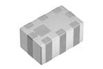
| 描述 | FILTER BANDPASS WLAN&BLUETOOTH信号调节 Filter BAL BP 2.4GHz WLAN & Bluetooth |
| 产品分类 | |
| 品牌 | TDK |
| 产品手册 | |
| 产品图片 |
|
| rohs | 符合RoHS无铅 / 符合限制有害物质指令(RoHS)规范要求 |
| 产品系列 | TDK DEA202450BT-7099A1DEA |
| mouser_ship_limit | 该产品可能需要其他文件才能进口到中国。 |
| 数据手册 | |
| 产品型号 | DEA202450BT-7099A1 |
| 产品 | Band Pass Filters |
| 产品目录页面 | |
| 产品种类 | 信号调节 |
| 介入损耗 | 2.3 dB |
| 其它名称 | 445-3972-1 |
| 包装 | 剪切带 (CT) |
| 商标 | TDK |
| 大小/尺寸 | 0.079" 长 x 0.049" 宽(2.00mm x 1.25mm) |
| 安装类型 | 表面贴装 |
| 封装 | Reel |
| 封装/外壳 | 0805(2012 公制),8 PC 板 |
| 封装/箱体 | 0805 (2012 metric) |
| 工作温度范围 | - 40 C to + 85 C |
| 工厂包装数量 | 2000 |
| 带宽 | 78MHz |
| 插入损耗 | 3dB |
| 标准包装 | 1 |
| 滤波器类型 | 带通 |
| 端接类型 | SMD/SMT |
| 类型 | Multilayer Chip Band Pass Filter (Balanced Output Type) |
| 纹波 | - |
| 阻抗 | 50 Ohms |
| 频率 | 2.441GHz 中心 |
| 频率范围 | 2402 MHz to 2480 MHz |
| 高度(最大值) | 0.031"(0.80mm) |



- 商务部:美国ITC正式对集成电路等产品启动337调查
- 曝三星4nm工艺存在良率问题 高通将骁龙8 Gen1或转产台积电
- 太阳诱电将投资9.5亿元在常州建新厂生产MLCC 预计2023年完工
- 英特尔发布欧洲新工厂建设计划 深化IDM 2.0 战略
- 台积电先进制程称霸业界 有大客户加持明年业绩稳了
- 达到5530亿美元!SIA预计今年全球半导体销售额将创下新高
- 英特尔拟将自动驾驶子公司Mobileye上市 估值或超500亿美元
- 三星加码芯片和SET,合并消费电子和移动部门,撤换高东真等 CEO
- 三星电子宣布重大人事变动 还合并消费电子和移动部门
- 海关总署:前11个月进口集成电路产品价值2.52万亿元 增长14.8%


PDF Datasheet 数据手册内容提取
R F C o m p o n e n t s June 2015 Multilayer Band Pass Filter (Balance Output Type) For 2402–2480MHz DEA202450BT-7099A1 2.0x1.25mm [EIA 0805]* * Dimensions Code JIS[EIA]
R F C o m p o n e n t s Multilayer Band Pass Filter (Balance Output Type) Conformity to RoHS Directive For 2402–2480MHz DEA202450BT-7099A1 SHAPES AND DIMENSIONS [Top view] 2.00±0.15 0.80max. (7) (6) (5) 5 (8) (4) 0.1 ± 5 2 1. (1) (2) (3) [Bottom view] 0.65±0.15 0.30±0.20 Terminal functions 1 Unbalanced port 2 DC feed 0 20 3 N.C. 0.30±0.2 0.25±0. 456 GBGaNNlaDDnced port 7 Balanced port 8 GND 0.20±0.20 0.35±0.15 Dimensions in mm RECOMMENDED LAND PATTERN EVALUATION BOARD 0.35 0 BAL 6 0. 5 5 9 3 1. 0. 0.20 BAL UNBAL 0.10 0.50 9 1 0. 0 5 0. 0.55 0.65 2.60 Dimensions in mm 0.707 EGxrpoousnedd Pcolapnpeer areas Ground Via Note1:Pin 2 of the filter provides a DC feed connection to the balanced DC feed capacitor Routing Via Lower layer trace ports. In the event that thisfunction is used, Pin 2 should be 0.80 connected to ground using a de-coupling capacitor. PCB Parameters: Note2:In the event that the pin 2 function is not used, the pin should be left Material: FR4 unconnected. Top metal to GND layer height: 0.1mm DC feed cap value: 15pF Dimensions in mm RoHS Directive Compliant Product: See the following for more details related to RoHS Directive compliant products. http://product.tdk.com/en/environment/rohs/ • All specifications are subject to change without notice. • Before using these products, be sure to request the delivery specifications. 2200115500660055 // rrff__bbppff__ddeeaa220022445500bbtt--77009999aa11__eenn..ffmm
R F C o m p o n e n t s DEA202450BT-7099A1 ELECTRICAL CHARACTERISTICS Frequency Range Item Min. Typ. Max. (MHz) Unbalanced Port Characteristic Impedance ((cid:2)) 50 (Nominal) Balanced Port Characteristic Impedance ((cid:2)) Matched to CSR BC04 IC Insertion Loss (dB) 2402 to 2480 — — 3 880 to 960 35 — — 1710 to 1880 22 — — Attenuation (dB) 1880 to 1910 20 — — 4804 to 4960 18 — — Return Loss at Unbalanced Port (dB) 2402 to 2480 8.5 — — Return Loss at Balanced Port (dB) 2402 to 2480 8.5 — — Phase Balance (deg.) 2402 to 2480 170 — 190 Amplitude Balance (dB) 2402 to 2480 –2 — 2 ・Ta: +25±5°C TEMPERATURE RANGE Operating temperature Storage temperature (°C) (°C) –40 to +85 –40 to +85 • All specifications are subject to change without notice. • Before using these products, be sure to request the delivery specifications. 2200115500660055 // rrff__bbppff__ddeeaa220022445500bbtt--77009999aa11__eenn..ffmm
R F C o m p o n e n t s DEA202450BT-7099A1 FREQUENCY CHARACTERISTICS SDS21 INSERTION LOSS SDS21 ATTENUATION 0 0 10 1 20 ()nsertion LossdB 32 ()AttenuationdB 4300 I 50 4 60 5 70 2000 2200 2400 2600 2800 3000 0 1000 2000 3000 4000 5000 6000 7000 8000 Frequency(MHz) Frequency(MHz) SSS11 RETURN LOSS at UNBALANCE PORT SDD22 RETURN LOSS at BALANCE PORT 0 0 10 10 ()Return LossdB 3200 ()Return LossdB 3200 40 40 50 50 2000 2200 2400 2600 2800 3000 2000 2200 2400 2600 2800 3000 Frequency(MHz) Frequency(MHz) PHASE BALANCE AMPLITUDE BALANCE 200 3 195 2 190 )eg. 185 ()edB 1 (anced 180 Balanc 0 Bal de hase 175 mplitu –1 P A 170 –2 165 160 –3 2000 2200 2400 2600 2800 3000 2000 2200 2400 2600 2800 3000 Frequency(MHz) Frequency(MHz) • All specifications are subject to change without notice. • Before using these products, be sure to request the delivery specifications. 2200115500660055 // rrff__bbppff__ddeeaa220022445500bbtt--77009999aa11__eenn..ffmm
R F C o m p o n e n t s RECOMMENDED REFLOW PROFILE Preheating Soldering Peak T4 3°C/sec 6°C/sec or lower or lower e ur T3 T3 at er p m e T T2 T: t3 T1 t1 t2 t: Time Soldering Preheating Critical zone (T3 to T4) Peak Temp. Time Temp. Time Temp. Time T1 T2 t1 T3 t2 T4 t3 150°C 200°C 60 to 120sec 217°C 60 to 120sec 240 to 260°C 30sec max. t3 : Time within 5°C of actual peak temperature The maximum number of reflow is 3. (cid:129)All specifications are subject to change without notice. (cid:129)Before using these products, be sure to request the delivery specifications.
R F C o m p o n e n t s REMINDERS FOR USING THESE PRODUCTS Before using these products, be sure to request the delivery specifications. SAFETY REMINDERS Please pay sufficient attention to the warnings for safe designing when using these products. REMINDERS The products listed on this catalog are intended for use in general electronic equipment (AV equipment, telecommunications equipment, home appliances, amusement equipment, computer equipment, personal equipment, office equipment, measurement equipment, industrial robots) under a normal operation and use condition. The products are not designed or warranted to meet the requirements of the applications listed below, whose performance and/or quality require a more stringent level of safety or reliability, or whose failure, malfunction or trouble could cause serious damage to society, person or property. Please understand that we are not responsible for any damage or liability caused by use of the products in any of the applications below or for any other use exceeding the range or conditions set forth in this catalog. (1) Aerospace/Aviation equipment (8) Public information-processing equipment (2) Transportation equipment (cars, electric trains, ships, etc.) (9) Military equipment (3) Medical equipment (10) Electric heating apparatus, burning equipment (4) Power-generation control equipment (11) Disaster prevention/crime prevention equipment (5) Atomic energy-related equipment (12) Safety equipment (6) Seabed equipment (13) Other applications that are not considered general-purpose (7) Transportation control equipment applications When using this product in general-purpose applications, you are kindly requested to take into consideration securing protection circuit/ equipment or providing backup circuits, etc., to ensure higher safety. • All specifications are subject to change without notice. • Before using these products, be sure to request the delivery specifications. 2200115500660055 // rrff__bbppff__ddeeaa220022445500bbtt--77009999aa11__eenn..ffmm
Mouser Electronics Authorized Distributor Click to View Pricing, Inventory, Delivery & Lifecycle Information: T DK: DEA202450BT-7099A1
 Datasheet下载

