ICGOO在线商城 > 开发板,套件,编程器 > 评估板 - 数模转换器 (DAC) > DC778A

 Datasheet下载
- 型号: DC778A
- 制造商: LINEAR TECHNOLOGY
- 库位|库存: xxxx|xxxx
- 要求:
| 数量阶梯 | 香港交货 | 国内含税 |
| +xxxx | $xxxx | ¥xxxx |
查看当月历史价格
查看今年历史价格
DC778A产品简介:
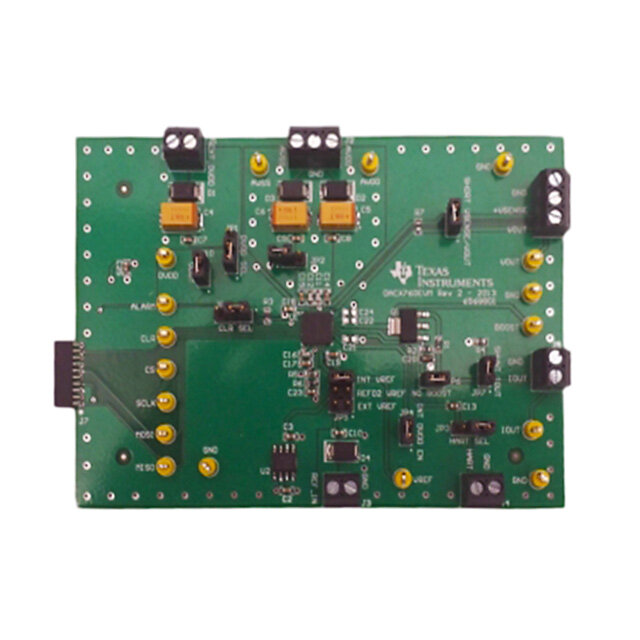
ICGOO电子元器件商城为您提供DC778A由LINEAR TECHNOLOGY设计生产,在icgoo商城现货销售,并且可以通过原厂、代理商等渠道进行代购。 DC778A价格参考。LINEAR TECHNOLOGYDC778A封装/规格:评估板 - 数模转换器 (DAC), LTC2602 16 Bit Digital to Analog Converter (DAC) Evaluation Board。您可以下载DC778A参考资料、Datasheet数据手册功能说明书,资料中有DC778A 详细功能的应用电路图电压和使用方法及教程。
| 参数 | 数值 |
| 产品目录 | 编程器,开发系统 |
| DAC数 | 2 |
| DAC类型 | 电压 |
| 描述 | BOARD DAC LTC2602 |
| 产品分类 | 评估板 - 数模转换器 (DAC) |
| 品牌 | Linear Technology |
| 数据手册 | http://www.linear.com/docs/1068http://cds.linear.com/docs/37352 |
| 产品图片 |
|
| 产品型号 | DC778A |
| rohs | 无铅 / 符合限制有害物质指令(RoHS)规范要求 |
| 产品系列 | QuikEval™ |
| 位数 | 16 |
| 使用的IC/零件 | LTC2602 |
| 工作温度 | 0°C ~ 70°C |
| 建立时间 | 10µs |
| 所含物品 | 板 |
| 数据接口 | MICROWIRE™,串行,SPI™ |
| 标准包装 | 1 |
| 相关产品 | /product-detail/zh/LTC2602CMS8%23PBF/LTC2602CMS8%23PBF-ND/963537/product-detail/zh/LTC2602IMS8%23PBF/LTC2602IMS8%23PBF-ND/963512/product-detail/zh/LTC2602IMS8%23TRPBF/LTC2602IMS8%23TRPBF-ND/960387/product-detail/zh/LTC2602CMS8%23TRPBF/LTC2602CMS8%23TRPBF-ND/958602/product-detail/zh/LTC2602IMS8/LTC2602IMS8-ND/694942/product-detail/zh/LTC2602CMS8/LTC2602CMS8-ND/694941/product-detail/zh/LTC2602CMS8%23TR/LTC2602CMS8%23TR-ND/693199/product-detail/zh/LTC2602IMS8%23TR/LTC2602IMS8%23TR-ND/693037 |
| 设计资源 | http://cds.linear.com/docs/37353http://cds.linear.com/docs/37354 |
| 软件下载 | http://ltspice.linear.com/software/ltcqev.exe |
| 采样率(每秒) | - |


PDF Datasheet 数据手册内容提取
DEMO MANUAL DC778A LTC2602 Dual 16-Bit Rail-to-Rail V DAC OUT DESCRIPTION Demonstration circuit 778A features the LTC®2602 dual Another feature of this board is the onboard LTC2422 16-Bit DAC. This device establishes a new board-density 20-bit ADC for monitoring DAC output voltage. The 16ppm benchmark for 16-bit DACs and advances performance total error of this device is adequate for taking meaningful standards for output drive, load regulation, and crosstalk measurements of various LTC2602 parameters. in single-supply, voltage-output DACs. Design files for this circuit board are available at DC778A has many features for evaluating the performance http://www.linear.com/demo of the LTC2602. Onboard 5V, 4.096V, and 2.5V precision L, LT, LTC, LTM, Linear Technology and the Linear logo are registered and QuikEval is a references are provided, and the LTC2602 may be powered trademark of Linear Technology Corporation. All other trademarks are the property of their respective owners. by the 5V reference for evaluating rail-to-rail operation. Figure 1. Proper Measurement Equipment Setup PERFORMANCE SUMMARY PARAMETER CONDITION VALUE Resolution 16 Bits Monotonicity V = 5V, V = 4.096V 16 Bits CC REF Differential Nonlinearity V = 5V, V = 4.096V ±1LSB CC REF Integral Nonlinearity V = 5V, V = 4.096V ±12LSB Typical CC REF Load Regulation V = V = 5V, Mid-Scale, I = ±15mA 2LSB/mA Max CC REF OUT DC Crosstalk Due to load current change on any other channel 3.5µV/mA dc778af 1
DEMO MANUAL DC778A QUICK START PROCEDURE Connect the DC778A to a DC590 USB serial controller correct control panel will be loaded automatically. Click using the supplied 14-conductor ribbon cable. Connect the COLLECT button to begin outputting codes to the DAC the DC590 to a host PC with a standard USB A/B cable. and reading back the resulting output voltage. Run the QuikEval™ evaluation software supplied with the Complete software documentation is available from the DC590 or download it from www.linear.com/software. The Help menu item, as features may be added periodically. Figure 2. QuikEval Software Screenshot HARDWARE SETUP Jumpers Analog Connections JP1 – V Select. Select 5V, 4.096V or 2.5V reference. VOUTA, VOUTB – LTC2602 Outputs REF To apply an external reference through the VREF turret, VREF – The VREF turret is connected directly to the refer- remove this jumper. ence terminals of the LTC2602 and LTC2422 ADC. When JP2 – V Select. V is taken either from the onboard 5V one of the onboard references is being used, the reference CC CC reference or the 5V regulated supply from the controller voltage may be monitored at this point. An external refer- board. Selecting the 5V reference for V and V allows ence may also be applied to this turret after removing JP1. CC REF characterization of rail-to-rail operation of the LTC2600. Grounding and Power Connections JP3 – ADC Disable. Set to ON for operation with the DC590 serial controller. When using in the customer’s end ap- Power (VCC) – Normally DC778A is powered by the DC590 plication, the ADC can be completely disabled by setting controller. VCC can be supplied to this turret, however jumper to DISABLE. the power supply on the DC590 must be disabled! Refer to the DC590 quick start guide for more details on this For very sensitive noise measurements when using the mode of operation. LTC supplied software, set the output voltage and stop reading voltage via the collect button on the control panel. dc778af 2
DEMO MANUAL DC778A HARDWARE SETUP Grounding – Separate power and signal grounds are ground planes at the top and bottom edges of the board, provided. Any large currents drawn from the DAC outputs and to the two turrets labeled GND. Use signal ground as should be returned to the power ground. Also, if an exter- the reference point for measurements and connections nal power supply is connected, the power ground should to external circuits. be used. The signal ground is connected to the exposed EXPERIMENTS The following experiments are intended to demonstrate spreadsheet. Next, take several readings at intermediate some of the outstanding features of the LTC2602. All can points. The readings should not deviate from the calcu- be performed using the onboard LTC2422 to monitor lated line by more than 64LSBs, and they will typically be the DAC output voltage. The indicated output voltage will within 12LSBs. typically agree with an HP3458A voltmeter to five digits. If a DAC is sinking or sourcing a significant current, then Load Regulation/DC Output Impedance the output voltage should be measured as close to the Select “5V REG” for V source. Set one of the outputs to CC DAC as possible. mid-scale (code 32768.) source or sink 15mA from one Most of the data sheet specifications use a 4.096V refer- of the DAC outputs by pulling it to power ground or V CC ence, so this is the preferred reference to use for these with an appropriate value resistor. The voltage change experiments. Using the 5V reference has the limitation that should be less than 2.25mV, corresponding to an output V may be slightly lower than V , which may affect the impedance of 0.15Ω. Output impedance is typically less CC REF full-scale error. Selecting the 5V reference as the source than 0.030Ω. (Measure DAC voltage at the output pin if for V overcomes this, however the total current that the using a voltmeter.) CC LTC2602 can source will be limited to approximately 5mA. Zero-Scale Error Using an external power supply is highly recommended for these experiments, especially those that draw significant Set one of the DACs to code 0. The measured output should current. Refer to the DC590 quick start guide for details. be less than 9mV and will typically be less than 1mV. Resolution Offset Error The onboard LTC2422 ADC has an input resolution of Set one of the DACs to code 256. The output voltage should 6μV. This will easily resolve a 1LSB (76μV for VREF = 5V, be within 9mV of the correct value, or VREF x 256/65535. 62.5μV for V = 4.096V) change in the LTC2602 output. REF Gain Error Set the DAC output to a voltage close to mid-scale. Select the FINE slider on the control panel with the mouse and Set one of the DACs to code 65,535. The output voltage use the right and left arrow keys to step the output by should be within 0.7% of V , and will typically be within REF single LSBs. The change should be clearly visible in the 0.2%. output graph. (It may be necessary to wait for the graph to clear if a large step has just occurred.) DC Crosstalk Set one of the DACs to mid-scale. Connect a 250Ω resistor Integral Nonlinearity from the output to V or power ground (to sink or source CC A rough measurement of INL can be taken using the onboard 10mA, respectively, when the 5V reference is being used.) ADC. Measure one of the LTC2602 outputs at code 256 The other output should not change by more than 3.5μV and 65,535 and calculate the slope and intercept using a per milliamp of load current. dc778af 3
DEMO MANUAL DC778A PARTS LIST ITEM QTY REFERENCE PART DESCRIPTION MANUFACTURE/PART NUMBER 1 2 C1, C2 CAP., X7R, 1µF 16V, 0603 TDK, C1608X7R1C105MT 2 3 C3, C7, C8 CAP., X7R, 0.1µF 16V, 0402 TDK, C1005X7R1C104MT 3 3 C4, C5, C6 CAP., X5R, 1µF 6.3V, 0402 TDK, C1005X5ROJ105MT 4 2 C9, C10 CAP., NPO, 100PF 50V, 0402 AVX, 04025A101MAT 5 7 E1, E2, E3, E4, E5, E6, E7 TESTPOINT, TURRET, 0.064" MILL-MAX, 2308-2 6 1 JP1 JMP, 2X3, 0.079CC COMM-CON, 2202S-06-G2 7 2 JP2, JP3 JMP, 3PIN 1 ROW 0.079CC COMM-CON, 2802S-03-G1 8 3 SHUNTS FOR JP1-JP3 PIN 1 AND 2 SHUNT, 0.079" CENTER COMM-CON CCIJ2MM-138G 9 1 J1 HEADER, 2X7PIN, 0.079CC MOLEX, 87331-1420 10 3 R1, R2, R3 RES., CHIP 4.99k 1/16W 1%, 0402 AAC, CR05-4991FM 11 3 R4, R6, R9 RES., CHIP 100Ω 1/16W 5%, 0402 AAC, CR05-101JM 12 2 R5, R7 RES., CHIP 7.5k 1/16W 5%, 0402 AAC, CR05-752JM 13 1 R8 RES., CHIP 10k 1/16W 5%, 0402 AAC, CR05-103JM 14 1 U1 I.C., LTC2602CMS8, MSOP8 LINEAR TECH., LTC2602CMS8 15 1 U2 I.C., LTC2422CMS, MSOP10 LINEAR TECH., LTC2422CMS 16 1 U3 I.C., LT1790ACS6-5, SOT23-6 LINEAR TECH., LT1790ACS6-5 17 1 U4 I.C., LT1790ACS6-4.096, SOT23-6 LINEAR TECH., LT1790ACS6-4.096 18 1 U5 I.C., LT1790ACS6-2.5, SOT23-6 LINEAR TECH., LT1790ACS6-2.5 19 1 U6 I.C., 24LC025, TSSOP8 MICROCHIP, 24LC025 dc778af 4
DEMO MANUAL DC778A SCHEMATIC DIAGRAM dc778af 5 Information furnished by Linear Technology Corporation is believed to be accurate and reliable. However, no responsibility is assumed for its use. Linear Technology Corporation makes no representa- tion that the interconnection of its circuits as described herein will not infringe on existing patent rights.
DEMO MANUAL DC778A DEMONSTRATION BOARD IMPORTANT NOTICE Linear Technology Corporation (LTC) provides the enclosed product(s) under the following AS IS conditions: This demonstration board (DEMO BOARD) kit being sold or provided by Linear Technology is intended for use for ENGINEERING DEVELOPMENT OR EVALUATION PURPOSES ONLY and is not provided by LTC for commercial use. As such, the DEMO BOARD herein may not be complete in terms of required design-, marketing-, and/or manufacturing-related protective considerations, including but not limited to product safety measures typically found in finished commercial goods. As a prototype, this product does not fall within the scope of the European Union directive on electromagnetic compatibility and therefore may or may not meet the technical requirements of the directive, or other regulations. If this evaluation kit does not meet the specifications recited in the DEMO BOARD manual the kit may be returned within 30 days from the date of delivery for a full refund. THE FOREGOING WARRANTY IS THE EXCLUSIVE WARRANTY MADE BY THE SELLER TO BUYER AND IS IN LIEU OF ALL OTHER WARRANTIES, EXPRESSED, IMPLIED, OR STATUTORY, INCLUDING ANY WARRANTY OF MERCHANTABILITY OR FITNESS FOR ANY PARTICULAR PURPOSE. EXCEPT TO THE EXTENT OF THIS INDEMNITY, NEITHER PARTY SHALL BE LIABLE TO THE OTHER FOR ANY INDIRECT, SPECIAL, INCIDENTAL, OR CONSEQUENTIAL DAMAGES. The user assumes all responsibility and liability for proper and safe handling of the goods. Further, the user releases LTC from all claims arising from the handling or use of the goods. Due to the open construction of the product, it is the user’s responsibility to take any and all appropriate precautions with regard to electrostatic discharge. Also be aware that the products herein may not be regulatory compliant or agency certified (FCC, UL, CE, etc.). No License is granted under any patent right or other intellectual property whatsoever. LTC assumes no liability for applications assistance, customer product design, software performance, or infringement of patents or any other intellectual property rights of any kind. LTC currently services a variety of customers for products around the world, and therefore this transaction is not exclusive. Please read the DEMO BOARD manual prior to handling the product. Persons handling this product must have electronics training and observe good laboratory practice standards. Common sense is encouraged. This notice contains important safety information about temperatures and voltages. For further safety concerns, please contact a LTC applica- tion engineer. Mailing Address: Linear Technology 1630 McCarthy Blvd. Milpitas, CA 95035 Copyright © 2004, Linear Technology Corporation dc778af 6 Linear Technology Corporation LT 0613 • PRINTED IN USA 1630 McCarthy Blvd., Milpitas, CA 95035-7417 (408) 432-1900 ● FAX: (408) 434-0507 ● www.linear.com LINEAR TECHNOLOGY CORPORATION 2013