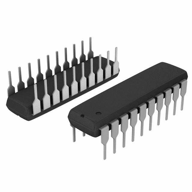
ICGOO在线商城 > 集成电路(IC) > 数据采集 - 数模转换器 > DAC7811IDGSR
- 型号: DAC7811IDGSR
- 制造商: Texas Instruments
- 库位|库存: xxxx|xxxx
- 要求:
| 数量阶梯 | 香港交货 | 国内含税 |
| +xxxx | $xxxx | ¥xxxx |
查看当月历史价格
查看今年历史价格
DAC7811IDGSR产品简介:
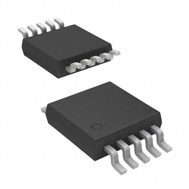
ICGOO电子元器件商城为您提供DAC7811IDGSR由Texas Instruments设计生产,在icgoo商城现货销售,并且可以通过原厂、代理商等渠道进行代购。 DAC7811IDGSR价格参考。Texas InstrumentsDAC7811IDGSR封装/规格:数据采集 - 数模转换器, 12 位 数模转换器 1 10-VSSOP。您可以下载DAC7811IDGSR参考资料、Datasheet数据手册功能说明书,资料中有DAC7811IDGSR 详细功能的应用电路图电压和使用方法及教程。
DAC7811IDGSR是德州仪器(Texas Instruments)生产的一款16位数模转换器(DAC),属于数据采集系统中的数模转换器类别。它具有低功耗、高精度和串行接口等特点,适用于多种工业和消费类应用场景。以下是其主要应用场景:

1. 工业自动化与控制
   DAC7811IDGSR可用于工业自动化设备中,例如可编程逻辑控制器(PLC)、数据采集系统和过程控制系统。通过将数字信号转换为模拟信号,它可以精确地控制电机速度、阀门开度或其他模拟量输出。

2. 医疗设备
   在医疗领域,该芯片可用于需要高精度信号生成的设备,如心电图机(ECG)、超声波设备或患者监护仪。其低功耗和高分辨率特性使其非常适合便携式或电池供电的医疗设备。

3. 通信系统
   DAC7811IDGSR可用于通信设备中生成高质量的模拟信号,例如调制解调器、无线发射器或信号发生器。它的串行接口设计简化了与微控制器或数字信号处理器(DSP)的连接。

4. 音频应用
   由于其16位分辨率和良好的线性度,DAC7811IDGSR也可用于音频设备中,例如数字音频播放器、音效处理器或专业音频设备。它能够提供高质量的音频信号输出。

5. 测试与测量设备
   在测试与测量领域,DAC7811IDGSR可用于信号发生器、示波器校准或数据记录仪等设备中。其高精度特性确保了测试结果的准确性。

6. 汽车电子
   该芯片可用于汽车电子系统中,例如车载信息娱乐系统、传感器信号调节或电动助力转向(EPS)系统的控制单元。

总结来说,DAC7811IDGSR凭借其高精度、低功耗和灵活性,广泛应用于工业、医疗、通信、音频和汽车等领域,能够满足各种对模拟信号输出有严格要求的应用场景。
| 参数 | 数值 |
| 产品目录 | 集成电路 (IC) |
| 描述 | IC DAC 12BIT MULTIPLYING 10-MSOP |
| 产品分类 | |
| 品牌 | Texas Instruments |
| 数据手册 | |
| 产品图片 |
|
| 产品型号 | DAC7811IDGSR |
| rohs | 无铅 / 符合限制有害物质指令(RoHS)规范要求 |
| 产品系列 | - |
| 产品培训模块 | http://www.digikey.cn/PTM/IndividualPTM.page?site=cn&lang=zhs&ptm=13240 |
| 产品目录页面 | |
| 位数 | 12 |
| 供应商器件封装 | 10-VSSOP |
| 其它名称 | 296-19660-1 |
| 制造商产品页 | http://www.ti.com/general/docs/suppproductinfo.tsp?distId=10&orderablePartNumber=DAC7811IDGSR |
| 包装 | 剪切带 (CT) |
| 安装类型 | 表面贴装 |
| 封装/外壳 | 10-TFSOP,10-MSOP(0.118",3.00mm 宽) |
| 工作温度 | -40°C ~ 125°C |
| 建立时间 | 200ns |
| 数据接口 | DSP,MICROWIRE™,QSPI™,串行,SPI™ |
| 标准包装 | 1 |
| 电压源 | 单电源 |
| 转换器数 | 1 |
| 输出数和类型 | 2 电流,单极2 电流,双极 |
| 配用 | /product-detail/zh/DAC7811EVM/296-18684-ND/863456 |
| 采样率(每秒) | - |





- 商务部:美国ITC正式对集成电路等产品启动337调查
- 曝三星4nm工艺存在良率问题 高通将骁龙8 Gen1或转产台积电
- 太阳诱电将投资9.5亿元在常州建新厂生产MLCC 预计2023年完工
- 英特尔发布欧洲新工厂建设计划 深化IDM 2.0 战略
- 台积电先进制程称霸业界 有大客户加持明年业绩稳了
- 达到5530亿美元!SIA预计今年全球半导体销售额将创下新高
- 英特尔拟将自动驾驶子公司Mobileye上市 估值或超500亿美元
- 三星加码芯片和SET,合并消费电子和移动部门,撤换高东真等 CEO
- 三星电子宣布重大人事变动 还合并消费电子和移动部门
- 海关总署:前11个月进口集成电路产品价值2.52万亿元 增长14.8%


PDF Datasheet 数据手册内容提取
Product Order Technical Tools & Support & Reference Folder Now Documents Software Community Design DAC7811 SBAS337E–APRIL2005–REVISEDMARCH2018 DAC7811 12-Bit, Serial Input, Multiplying Digital-to-Analog Converter 1 Features 3 Description • 2.7-Vto5.5-VSupplyOperation The DAC7811 is a CMOS, 12-bit, current output 1 digital-to-analog converter (DAC). This device • 50-MHzSerialInterface operates from a 2.7-V to 5.5-V power supply, making • 10-MHzMultiplyingBandwidth it suitable for battery-powered and many other • ±15-VReferenceInput applications. • LowGlitchEnergy:5nV-s This DAC uses a double-buffered 3-wire serial • ExtendedTemperatureRange: interface that is compatible with SPI, QSPI™, MICROWIRE, and most DSP interface standards. In –40°Cto+125°C addition, a serial data out pin (SDO) allows for daisy- • 10-PinVSSOPPackage chaining when multiple devices are used. Data • 12-BitMonotonic readback allows the user to read the contents of the • 4-QuadrantMultiplication DAC register via the SDO pin. On power-up, the internalshiftregisterandlatchesarefilledwithzeroes • Power-OnResetWithBrownoutDetection andtheDACoutputsareatzeroscale. • Daisy-ChainMode The DAC7811 offers excellent 4-quadrant • ReadbackFunction multiplication characteristics, with large signal • Industry-StandardPinConfiguration multiplying bandwidth of 10 MHz. The applied external reference input voltage (V ) determines REF 2 Applications the full-scale output current. An integrated feedback resistor (R ) provides temperature tracking and full- • PortableBattery-PoweredInstruments FB scale voltage output when combined with an external • WaveformGenerators current-to-voltageprecisionamplifier. • AnalogProcessing The DAC7811 is available in a 10-lead VSSOP • ProgrammableAmplifiersandAttenuators package. • DigitallyControlledCalibration DeviceInformation(1) • ProgrammableFiltersandOscillators PARTNUMBER PACKAGE BODYSIZE(NOM) • CompositeVideo DAC7811 VSSOP(10) 3.00mm3.00mm • Ultrasound (1) Forallavailablepackages,seethepackageoptionaddendum attheendofthedatasheet. BlockDiagram V V DD REF DAC7811 R R FB 12-Bit IOUT1 R-2R DAC I 2 OUT DAC Register Power-On Reset Input Latch SYNC Control Logic and SCLK Input Shift Register SDO SDIN GND Copyright © 2016, Texas Instruments Incorporated 1 An IMPORTANT NOTICE at the end of this data sheet addresses availability, warranty, changes, use in safety-critical applications, intellectualpropertymattersandotherimportantdisclaimers.PRODUCTIONDATA.
DAC7811 SBAS337E–APRIL2005–REVISEDMARCH2018 www.ti.com Table of Contents 1 Features.................................................................. 1 7.4 DeviceFunctionalModes........................................12 2 Applications........................................................... 1 8 ApplicationandImplementation........................ 15 3 Description............................................................. 1 8.1 ApplicationInformation............................................15 4 RevisionHistory..................................................... 2 8.2 TypicalApplication..................................................19 5 PinConfigurationandFunctions......................... 3 9 PowerSupplyRecommendations...................... 20 6 Specifications......................................................... 4 10 Layout................................................................... 21 6.1 AbsoluteMaximumRatings......................................4 10.1 LayoutGuidelines.................................................21 6.2 ESDRatings..............................................................4 10.2 LayoutExample....................................................21 6.3 RecommendedOperatingConditions.......................4 11 DeviceandDocumentationSupport................. 22 6.4 ThermalInformation..................................................4 11.1 DocumentationSupport........................................22 6.5 ElectricalCharacteristics...........................................5 11.2 ReceivingNotificationofDocumentationUpdates22 6.6 TypicalCharacteristics:V =5V............................6 11.3 CommunityResource............................................22 DD 6.7 TypicalCharacteristics:V =2.7V.........................9 11.4 Trademarks...........................................................22 DD 7 DetailedDescription............................................ 11 11.5 ElectrostaticDischargeCaution............................22 7.1 Overview.................................................................11 11.6 Glossary................................................................22 7.2 FunctionalBlockDiagram.......................................11 12 Mechanical,Packaging,andOrderable Information........................................................... 22 7.3 FeatureDescription.................................................11 4 Revision History NOTE:Pagenumbersforpreviousrevisionsmaydifferfrompagenumbersinthecurrentversion. ChangesfromRevisionD(March2016)toRevisionE Page • ChangedFigure28SDOpintimingtoremoveHi-Z............................................................................................................ 14 ChangesfromRevisionC(July2007)toRevisionD Page • AddedESDRatingstable,FeatureDescriptionsection,DeviceFunctionalModes,ApplicationandImplementation section,PowerSupplyRecommendationssection,Layoutsection,DeviceandDocumentationSupportsection,and Mechanical,Packaging,andOrderableInformationsection ................................................................................................. 1 2 SubmitDocumentationFeedback Copyright©2005–2018,TexasInstrumentsIncorporated ProductFolderLinks:DAC7811
DAC7811 www.ti.com SBAS337E–APRIL2005–REVISEDMARCH2018 5 Pin Configuration and Functions DGSPackage 10-PinVSSOP TopView MSOP PACKAGE (TOP VIEW) IOUT1 1 10 RFB IOUT2 2 9 VREF GND 3 8 VDD SCLK 4 7 SDO SDIN 5 6 SYNC PinFunctions PIN TYPE DESCRIPTION NO. NAME 1 I 1 O DACCurrentOutput OUT 2 I 2 O DACAnalogGround.Thispinisnormallytiedtotheanaloggroundofthesystem. OUT 3 GND G Groundpin. SerialClockInput.Bydefault,dataisclockedintotheinputshiftregisteronthefallingedgeofthe 4 SCLK I serialclockinput.Alternatively,bymeansoftheserialcontrolbits,thedevicemaybeconfiguredsuch thatdataisclockedintotheshiftregisterontherisingedgeofSCLK. SerialDataInput.Dataisclockedintothe16-bitinputregisterontheactiveedgeoftheserialclock 5 SDIN I input.Bydefault,onpower-up,dataisclockedintotheshiftregisteronthefallingedgeofSCLK.The controlbitsallowtheusertochangetheactiveedgetotherisingedge. ActiveLowControlInput.Thisistheframesynchronizationsignalfortheinputdata.WhenSYNC goeslow,itpowersontheSCLKandDINbuffers,andtheinputshiftregisterisenabled.Datais 6 SYNC I loadedtotheshiftregisterontheactiveedgeofthefollowingclocks(power-ondefaultisfallingclock edge).Instand-alonemode,theserialinterfacecountstheclocksanddataislatchedtotheshift registeronthe16thactiveclockedge. SerialDataOutput.Thisallowsanumberofpartstobedaisy-chained.Bydefault,dataisclockedinto theshiftregisteronthefallingedgeandoutviaSDOontherisingedgeofSCLK.Datawillalwaysbe 7 SDO O clockedoutonthealternateedgetoloadingdatatotheshiftregister.WritingtheReadbackcontrol wordtotheshiftregistermakestheDACregistercontentsavailableforreadbackontheSDOpin, clockedoutontheoppositeedgestotheactiveclockedge. 8 V I PositivePowerSupplyInput.Thesepartscanbeoperatedfromasupplyof2.7Vto5.5V. DD 9 V I DACReferenceVoltageInput REF DACFeedbackResistorpin.EstablishvoltageoutputfortheDACbyconnectingtoexternalamplifier 10 R O FB output. Copyright©2005–2018,TexasInstrumentsIncorporated SubmitDocumentationFeedback 3 ProductFolderLinks:DAC7811
DAC7811 SBAS337E–APRIL2005–REVISEDMARCH2018 www.ti.com 6 Specifications 6.1 Absolute Maximum Ratings overoperatingfree-airtemperaturerange(unlessotherwisenoted)(1) MIN MAX UNIT V toGND –0.3 7 V DD DigitalinputvoltagetoGND –0.3 V +0.3 V DD I 1,I 2toGND –0.3 V +0.3 V OUT OUT DD Operatingtemperature –40 125 °C Junctiontemperature,(T max) 150 °C J Storagetemperature,T –65 150 °C stg (1) StressesbeyondthoselistedunderAbsoluteMaximumRatingsmaycausepermanentdamagetothedevice.Thesearestressratings only,whichdonotimplyfunctionaloperationofthedeviceattheseoranyotherconditionsbeyondthoseindicatedunderRecommended OperatingConditions.Exposuretoabsolute-maximum-ratedconditionsforextendedperiodsmayaffectdevicereliability. 6.2 ESD Ratings VALUE UNIT Human-bodymodel(HBM),perANSI/ESDA/JEDECJS-001(1) ±2000 V Electrostaticdischarge V (ESD) Charged-devicemodel(CDM),perJEDECspecificationJESD22-C101(2) ±1000 (1) JEDECdocumentJEP155statesthat500-VHBMallowssafemanufacturingwithastandardESDcontrolprocess. (2) JEDECdocumentJEP157statesthat250-VCDMallowssafemanufacturingwithastandardESDcontrolprocess. 6.3 Recommended Operating Conditions overoperatingfree-airtemperaturerange(unlessotherwisenoted) MIN NOM MAX UNIT V SupplyvoltagetoGND 2.7 5.5 V DD V Referencevoltage –15 15 V REF V =2.7V 0.6 V DD V Inputlowvoltage IL V =5V 0.8 V DD V =2.7V 2.1 V DD V Inputhighvoltage IH V =5V 2.4 V DD T Operatingambienttemperature –40 125 °C A 6.4 Thermal Information DAC7811 THERMALMETRIC(1) DGS(VSSOP) UNIT 10PINS R Junction-to-ambientthermalresistance 165.6 °C/W θJA R Junction-to-case(top)thermalresistance 55.4 °C/W θJC(top) R Junction-to-boardthermalresistance 85.6 °C/W θJB ψ Junction-to-topcharacterizationparameter 6.2 °C/W JT ψ Junction-to-boardcharacterizationparameter 84.2 °C/W JB R Junction-to-case(bottom)thermalresistance N/A °C/W θJC(bot) (1) Formoreinformationabouttraditionalandnewthermalmetrics,seetheSemiconductorandICPackageThermalMetricsapplication report. 4 SubmitDocumentationFeedback Copyright©2005–2018,TexasInstrumentsIncorporated ProductFolderLinks:DAC7811
DAC7811 www.ti.com SBAS337E–APRIL2005–REVISEDMARCH2018 6.5 Electrical Characteristics V =2.7Vto5.5V;I 1=VirtualGND;I 2=0V;V =10V;T =fulloperatingtemperature.Allspecifications–40°Cto DD OUT OUT REF A 125°C,unlessotherwisenoted. PARAMETER TESTCONDITIONS MIN TYP MAX UNIT STATICPERFORMANCE Resolution 12 Bits Relativeaccuracy ±1 LSB Differentialnonlinearity ±1 LSB Outputleakagecurrent Data=0000h,T =25°C ±5 nA A Outputleakagecurrent Data=0000h,T =T ±25 nA A MAX Full-scalegainerror AllonesloadedtoDACregister ±5 ±10 mV Full-scaletempco(1) ±5 ppm/°C Outputcapacitance(1) Codedependent 5 pF REFERENCEINPUT Inputresistance 8 10 12 kΩ R resistance 8 10 12 kΩ FB LOGICINPUTSANDOUTPUT(1) I Inputleakagecurrent 10 µA IL C Inputcapacitance 10 pF IL INTERFACETIMING(seeFigure28) f 50 MHz CLK t Clockperiod 20 ns C t Clockpulsewidthhigh 8 ns CH t Clockpulsewidthlow 8 ns CC SYNCfallingedgetoSCLK t 13 ns CSS activeedgesetuptime SCLKactiveedgetoSYNC t 5 ns CST risingedgeholdtime t Datasetuptime 5 ns DS t Dataholdtime 3 ns DH t SYNChightime 30 ns SH SYNCinactiveedgetoSDO VDD=2.7V 25 35 ns t DDS valid V =5V 20 30 ns DD POWERREQUIREMENTS I (normaloperation) Logicinputs=0V 5 µA DD V =4.5Vto5.5V V =V andV =GND 0.8 5 µA DD IH DD IL V =2.7Vto3.6V V =V andV =GND 0.4 2.5 µA DD IH DD IL ACCHARACTERISTICS(1) Outputvoltagesettlingtime 0.2 µs ReferencemultiplyingBW V =7V ,Data=FFFh 10 MHz REF PP V =0Vto10V, DACglitchimpulse REF 5 nV-s Data=7FFhto800hto7FFh FeedthrougherrorV /V Data=000h,V =100kHz –60 dB OUT REF REF Digitalfeedthrough 2 nV-s Totalharmonicdistortion –105 dB Outputspotnoisevoltage 18 nV/√Hz (1) Specifiedbydesignandcharacterization;notproductiontested. Copyright©2005–2018,TexasInstrumentsIncorporated SubmitDocumentationFeedback 5 ProductFolderLinks:DAC7811
DAC7811 SBAS337E–APRIL2005–REVISEDMARCH2018 www.ti.com 6.6 Typical Characteristics: V = 5 V DD AtT =25°C,unlessotherwisenoted. A 1.0 1.0 T = +25°C T = +25°C 0.8 A 0.8 A V = +10V V = +10V 0.6 REF 0.6 REF 0.4 0.4 INL (LSB) -00..202 DNL (LSB) -00..202 -0.4 -0.4 -0.6 -0.6 -0.8 -0.8 -1.0 -1.0 0 512 1024 1536 2048 2560 3072 3584 4096 0 512 1024 1536 2048 2560 3072 3584 4096 Digital Input Code Digital Input Code Figure1.LinearityErrorvsDigitalInputCode Figure2.DifferentialLinearityErrorvsDigitalInputCode 1.0 1.0 T =-40°C T =-40°C 0.8 A 0.8 A V = +10V V = +10V 0.6 REF 0.6 REF 0.4 0.4 B) 0.2 B) 0.2 S S INL (L -0.02 DNL (L -0.02 -0.4 -0.4 -0.6 -0.6 -0.8 -0.8 -1.0 -1.0 0 512 1024 1536 2048 2560 3072 3584 4096 0 512 1024 1536 2048 2560 3072 3584 4096 Digital Input Code Digital Input Code Figure3.LinearityErrorvsDigitalInputCode Figure4.DifferentialLinearityErrorvsDigitalInputCode 1.0 1.0 T = +125°C T = +125°C 0.8 A 0.8 A V = +10V V = +10V 0.6 REF 0.6 REF 0.4 0.4 B) 0.2 B) 0.2 S S INL (L -0.02 DNL (L -0.02 -0.4 -0.4 -0.6 -0.6 -0.8 -0.8 -1.0 -1.0 0 512 1024 1536 2048 2560 3072 3584 4096 0 512 1024 1536 2048 2560 3072 3584 4096 Digital Input Code Digital Input Code Figure5.LinearityErrorvsDigitalInputCode Figure6.DifferentialLinearityErrorvsDigitalInputCode 6 SubmitDocumentationFeedback Copyright©2005–2018,TexasInstrumentsIncorporated ProductFolderLinks:DAC7811
DAC7811 www.ti.com SBAS337E–APRIL2005–REVISEDMARCH2018 Typical Characteristics: V = 5 V (continued) DD AtT =25°C,unlessotherwisenoted. A 0.9 6 0 0xFFF 0.8 -6 0x800 V = +5.0V -12 0x400 0.7 DD -18 0x200 mA) 0.6 B) --2340 00xx100800 upply Current ( 000...543 Attenuation (d -------34456676286062 0000000xxxxxxx000000042100000008421 Digital Code S 0.2 VDD= +3.0V ---789840 0.1 -96 0x000 -102 0 10 100 1k 10k 100k 1M 10M 100M 0 1.0 2.0 3.0 4.0 5.0 Bandwidth (Hz) Logic Input Voltage (V) Figure7.SupplyCurrentvsLogicInputVoltage Figure8.ReferenceMultiplyingBandwidth v) v) di di V/ V/ m m 0 0 e (5 Code 2047 to 2048 e (5 Code 2048 to 2047 g g a a olt olt V V ut ut p p Out DAC Update Out DAC Update Time (50ns/div) Time (50ns/div) Figure9.MidscaleDACGlitch Figure10.MidscaleDACGlitch 0 V = +10V -0.2 REF Small Signal Settling -0.4 0 %)9 -0.6 ge ( mV) -0.8 Output Volta Gain Error ( ---111...024 0 1 DAC Update -1.6 -1.8 -2.0 Time (20ns/div) -40 -20 0 20 40 60 80 100 120 Temperature (°C) Figure11.DACSettlingTime Figure12.GainErrorvsTemperature Copyright©2005–2018,TexasInstrumentsIncorporated SubmitDocumentationFeedback 7 ProductFolderLinks:DAC7811
DAC7811 SBAS337E–APRIL2005–REVISEDMARCH2018 www.ti.com Typical Characteristics: V = 5 V (continued) DD AtT =25°C,unlessotherwisenoted. A 2.0 1.6 V = +10V V = +10V REF REF 1.8 1.4 1.6 Current (A)m 111...420 akage (nA) 110...208 scent 0.8 VDD= +5.0V put Le 0.6 Quie 00..64 VDD= +3.0V Out 0.4 0.2 0.2 0 0 -40 -20 0 20 40 60 80 100 120 -40 -20 0 20 40 60 80 100 120 Temperature (°C) Temperature (°C) Figure13.SupplyCurrentvsTemperature Figure14.OutputLeakagevsTemperature 8 SubmitDocumentationFeedback Copyright©2005–2018,TexasInstrumentsIncorporated ProductFolderLinks:DAC7811
DAC7811 www.ti.com SBAS337E–APRIL2005–REVISEDMARCH2018 6.7 Typical Characteristics: V = 2.7 V DD AtT =25°C,unlessotherwisenoted. A 1.0 1.0 T = +25°C T = +25°C 0.8 A 0.8 A R = +10V V = +10V 0.6 REF 0.6 REF 0.4 0.4 B) 0.2 B) 0.2 S S INL (L -0.02 DNL (L -0.02 -0.4 -0.4 -0.6 -0.6 -0.8 -0.8 -1.0 -1.0 0 512 1024 1536 2048 2560 3072 3584 4096 0 512 1024 1536 2048 2560 3072 3584 4096 Digital Input Code Digital Input Code Figure15.LinearityErrorvsDigitalInputCode Figure16.DifferentialLinearityErrorvsDigitalInputCode 1.0 1.0 T =-40°C T =-40°C 0.8 A 0.8 A V = +10V V = +10V 0.6 REF 0.6 REF 0.4 0.4 B) 0.2 B) 0.2 S S INL (L -0.02 DNL (L -0.02 -0.4 -0.4 -0.6 -0.6 -0.8 -0.8 -1.0 -1.0 0 512 1024 1536 2048 2560 3072 3584 4096 0 512 1024 1536 2048 2560 3072 3584 4096 Digital Input Code Digital Input Code Figure17.LinearityErrorvsDigitalInputCode Figure18.DifferentialLinearityErrorvsDigitalInputCode 1.0 1.0 T = +125°C T = +125°C 0.8 A 0.8 A V = +10V V = +10V 0.6 REF 0.6 REF 0.4 0.4 INL (LSB) -00..202 DNL (LSB) -00..202 -0.4 -0.4 -0.6 -0.6 -0.8 -0.8 -1.0 -1.0 0 512 1024 1536 2048 2560 3072 3584 4096 0 512 1024 1536 2048 2560 3072 3584 4096 Digital Input Code Digital Input Code Figure19.LinearityErrorvsDigitalInputCode Figure20.DifferentialLinearityErrorvsDigitalInputCode Copyright©2005–2018,TexasInstrumentsIncorporated SubmitDocumentationFeedback 9 ProductFolderLinks:DAC7811
DAC7811 SBAS337E–APRIL2005–REVISEDMARCH2018 www.ti.com Typical Characteristics: V = 2.7 V (continued) DD AtT =25°C,unlessotherwisenoted. A div) div) V/ V/ m m 0 0 e (5 Code 2048 to 2047 e (5 Code 2047 to 2048 g g a a Volt Volt ut ut p p ut ut O O DAC Update DAC Update Time (50ns/div) Time (50ns/div) Figure21.MidscaleDACGlitch Figure22.MidscaleDACGlitch 0 1.6 V = +10V V = +10V -0.2 REF REF 1.4 -0.4 Gain Error (mV) -----00111.....68024 utput Leakage (nA) 1100....2086 O 0.4 -1.6 -1.8 0.2 -2.0 0 -40 -20 0 20 40 60 80 100 120 -40 -20 0 20 40 60 80 100 120 Temperature (°C) Temperature (°C) Figure23.GainErrorvsTemperature Figure24.OutputLeakagevsTemperature 10 SubmitDocumentationFeedback Copyright©2005–2018,TexasInstrumentsIncorporated ProductFolderLinks:DAC7811
DAC7811 www.ti.com SBAS337E–APRIL2005–REVISEDMARCH2018 7 Detailed Description 7.1 Overview The DAC7811 is a CMOS, 12-bit, current output digital-to-analog converter (DAC). This device operates from a 2.7-V to 5.5-V power supply, making it suitable for battery-powered and many other applications. This DAC uses a double-buffered 3-wire serial interface that is compatible with SPI, QSPI™, MICROWIRE, and most DSP interface standards. In addition, a serial data out pin (SDO) allows for daisy-chaining when multiple devices are used. Data readback allows the user to read the contents of the DAC register via the SDO pin. On power-up, the internalshiftregisterandlatchesarefilledwithzeroesandtheDACoutputsareatzeroscale. 7.2 Functional Block Diagram V V DD REF DAC7811 R R FB 12-Bit IOUT1 R-2R DAC I 2 OUT DAC Register Power-On Reset Input Latch SYNC Control Logic and SCLK Input Shift Register SDO SDIN GND Copyright © 2016, Texas Instruments Incorporated 7.3 Feature Description The DAC7811 is a single channel, current output, 12-bit digital-to-analog converter (DAC). The architecture, illustrated in Figure 25, is an R-2R ladder configuration with the three MSBs segmented. Each 2R leg of the ladder is either switched to I 1 or the I 2 terminal. The I 1 terminal of the DAC is held at a virtual GND OUT OUT OUT potential by the use of an external I/V converter op amp. The R-2R ladder is connected to an external reference input V that determines the DAC full-scale current. The R-2R ladder presents a code independent load REF impedance to the external reference of 10kΩ ±20%. The external reference voltage can vary over a range of –15V to +15V, thus providing bipolar I current operation. By using an external I/V converter and the DAC7811 OUT R resistor,outputvoltagerangesof –V toV canbegenerated. FB REF REF R R R R V REF 2R 2R 2R 2R R R FB I 1 OUT I 2 OUT DB11 DB10 DB9 DB0 (MSB) (LSB) Figure25. EquivalentR-2RDACCircuit Copyright©2005–2018,TexasInstrumentsIncorporated SubmitDocumentationFeedback 11 ProductFolderLinks:DAC7811
DAC7811 SBAS337E–APRIL2005–REVISEDMARCH2018 www.ti.com Feature Description (continued) When using an external I/V converter and the DAC7811 R resistor, the DAC output voltage is given by FB Equation1: §CODE• V (cid:16)V u¤ ‚ OUT REF ' 4096 „ (1) Each DAC code determines the 2R leg switch position to either GND or I . Because the DAC output OUT impedance as seen looking into the I 1 terminal changes versus code, the external I/V converter noise gain OUT will also change. Because of this, the external I/V converter op amp must have a sufficiently low offset voltage such that the amplifier offset is not modulated by the DAC I 1 terminal impedance change. External op amps OUT with large offset voltages can produce INL errors in the transfer function of the DAC7811 due to offset modulationversusDACcode. For best linearity performance of the DAC7811, a low offset voltage op amp (such as the OPA277) is recommended(seeFigure26).ThiscircuitallowsV swingingfrom –10Vto10V. REF V DD 15V V R DD FB V+ V DAC7811 I 1 REF OUT GND IOUT2 OPA277 VOUT V(cid:16) (cid:16)15V Copyright © 2016, Texas Instruments Incorporated Figure26. VoltageOutputConfiguration 7.4 Device Functional Modes 7.4.1 SerialInterface The DAC7811 has a 3-wire serial interface (SYNC, SCLK, and SDIN), which is compatible with SPI, QSPI, and MICROWIRE interface standards as well as most Digital Signal Processor (DSP) devices. See the Serial Write Operation timing diagram (Figure 28) for an example of a typical write sequence. The write sequence begins by bringing the SYNC line low. Data from the DIN line are clocked into the 16-bit shift register on the falling edge of SCLK. The serial clock frequency can be as high as 50MHz, making the DAC7811 compatible with high-speed DSPs. The SDIN and SCLK input buffers are gated off while SYNC is high which minimizes the power dissipation of the digital interface. After SYNC goes low, the digital interface will respond to the SDIN and SCLK input signals and data can now be shifted into the device. If an inactive clock edge occurs after SYNC goes low, but before the first active clock edge, it will be ignored. If the SDO pin is being used then SYNC must remain low untilaftertheinactiveclockedgethatfollowsthe16thactiveclockedge. 7.4.2 InputShiftRegister The input shift register is 16 bits wide, as shown in Figure 27. The four MSBs are the control bits C3–C0; these bits determine which function will be executed at the rising edge of SYNC in daisy-chain mode or the 16th active clock edge in stand-alone mode. The remaining 12 bits are the data bits. On a load and update command (C3–C0 = 0001) these 12 data bits will be transferred to the DAC register; otherwise, they have no effect. Table1showsserialshiftregisterandDACregisteroperationwithCLKand SYNCpinsettings. 12 SubmitDocumentationFeedback Copyright©2005–2018,TexasInstrumentsIncorporated ProductFolderLinks:DAC7811
DAC7811 www.ti.com SBAS337E–APRIL2005–REVISEDMARCH2018 Device Functional Modes (continued) 4CONTROLBITS 12DATABITS B15 B0 (MSB) B14 B13 B12 B11 B10 B9 B8 B7 B6 B5 B4 B3 B2 B1 (LSB) C3 C2 C1 C0 DB11 DB0 Figure27. Contentsofthe16-BitInputShiftRegister Table1.ControlLogicTruthTable(1) CLK SYNC SERIALSHIFTREGISTER DACREGISTER X H Noeffect Latched ↓– L Shiftregisterdataadvancedonebit Latched Indaisy-chainmode,thefunctionasdeterminedbyC3- Indaisy-chainmode,thecontentsmaychangeas X ↑+ C0isexecuted. determinedbyC3-C0. (1) ↓–Negativelogictransition,defaultCLKmode;↑+Positivelogictransition;X=Donotcare. 7.4.3 SYNCInterrupt(Stand-AloneMode) In a normal write sequence, the SYNC line is kept low for at least 16 falling edges of SCLK and the DAC is updated on the 16th falling edge. However, if SYNC is brought high before the 16th falling edge, this acts as an interrupt to the write sequence. The shift register is reset and the write sequence is seen as invalid. Neither an updateoftheDACregistercontentsnorachangeintheoperatingmodeoccurs. 7.4.4 Daisy-Chain The DAC7811 powers up in the daisy-chain mode which must be used when two or more devices are connected in tandem. The SCLK and SYNC signals are shared across all devices while the SDO output of the first device connects to the SDIN input of the following device, and so forth. In this configuration 16 SCLK cycles for each DAC7811inthechainarerequired.PleaserefertothetimingdiagramofFigure28. For n devices in a daisy-chain configuration, 16n SCLK cycles are required to shift in the entire input data stream. After 16n active SCLK edges are received following a falling SYNC, the data stream becomes complete, andSYNCcanbroughthightoupdatendevicessimultaneously. When SYNC is brought high, each device will execute the function defined by the four DAC control bits C3-C0 in its input shift register. For example, C3-C0 must be 0001 for each DAC in the chain that is to be updated with newdata,andC3-C0mustbe0000foreachDACinthechainwhosecontentsaretoremainunchanged. AcontinuousstreamcontainingtheexactnumberofSCLKcyclesmaybesentfirstwhilethe SYNCsignalisheld low, and then raise SYNC at a later time. Nothing happens until the rising edge of SYNC, and then each DAC7811 in the chain will execute the function defined by the four DAC control bits C3-C0 in its input shift register. Copyright©2005–2018,TexasInstrumentsIncorporated SubmitDocumentationFeedback 13 ProductFolderLinks:DAC7811
DAC7811 SBAS337E–APRIL2005–REVISEDMARCH2018 www.ti.com t C SCLK t tCC tCST CSS t CH t SH SYNC t DH t DS DB15 DB0 DB15 DB0 SDIN (N) (N) (N + 1) (N + 1) t DDS DB15 DB0 SDO (N) (N) Figure28. DAC7811TimingDiagram 7.4.5 ControlBitsC3toC0 Control Bits C3 to C0 allow control of various functions of the DAC; see Table 2. Default settings of the DAC on powering up are as follows: Data clocked into shift register on falling clock edges; daisy-chain mode is enabled. Thedevicepowersonwithzero-scaleloadedintotheDACregisterandI lines.TheDACcontrolbitsallowthe OUT user to adjust certain features as part of an initialization sequence; for example, daisy-chaining may be disabled if not in use, active clock edge may be changed to rising edge, and DAC output may be cleared to either zero or midscale.TheusermayalsoinitiateareadbackoftheDACregistercontentsforverificationpurposes. Table2.SerialInputRegisterDataFormat,DataLoadedMSBFirst C3 C2 C1 C0 FUNCTIONIMPLEMENTED 0 0 0 0 Nooperation(power-ondefault) 0 0 0 1 Loadandupdate 0 0 1 0 Initiatereadback 0 0 1 1 Reserved 0 1 0 0 Reserved 0 1 0 1 Reserved 0 1 1 0 Reserved 0 1 1 1 Reserved 1 0 0 0 Reserved 1 0 0 1 Daisy-chaindisable 1 0 1 0 Clockdatatoshiftregisteronrisingedge 1 0 1 1 ClearDACoutputtozero 1 1 0 0 ClearDACoutputtomidscale 1 1 0 1 Reserved 1 1 1 0 Reserved 1 1 1 1 Reserved 14 SubmitDocumentationFeedback Copyright©2005–2018,TexasInstrumentsIncorporated ProductFolderLinks:DAC7811
DAC7811 www.ti.com SBAS337E–APRIL2005–REVISEDMARCH2018 8 Application and Implementation NOTE Information in the following applications sections is not part of the TI component specification, and TI does not warrant its accuracy or completeness. TI’s customers are responsible for determining suitability of components for their purposes. Customers should validateandtesttheirdesignimplementationtoconfirmsystemfunctionality. 8.1 Application Information The 2.7-V to 5.5-V supply operation makes the DAC7811 a viable candidate for battery operated applications, such as waveform generators, programmable amplifiers, and any mobile platforms that may require analog outputs and processing. Additionally, the large signal multiplying bandwidth of the DAC7811 makes it an excellentchoiceforprogrammablefiltersandoscillators. 8.1.1 UnipolarOperationUsingDAC7811 To generate a positive voltage output, a negative reference is input to the DAC7811. This design is suggested instead of using an inverting amp to invert the output as a result of resistor tolerance errors. For a negative reference, VOUT and GND of the reference are level-shifted to a virtual ground and a –2.5-V input to the DAC7811withanopamp. +2.5V Reference V DD V V OUT IN GND V R C DD FB 1 V OPA277 REF DAC7811 I 1 OUT -2.5V OPA277 V GND I 2 OUT OUT 0 to 2.5V Copyright © 2016, Texas Instruments Incorporated Figure29. PositiveVoltageOutputCircuit 8.1.2 BipolarOperationUsingtheDAC7811 The DAC7811, as a 2-quadrant multiplying DAC, can be used to generate a unipolar output. The polarity of the full-scaleoutputIOUTistheinverseoftheinputreferencevoltageatVREF. Some applications require full 4-quadrant multiplying capabilities or bipolar output swing. As shown in Figure 30, external op amp U3 is added as a summing amp and has a gain of 2X that widens the output span to 5 V. A 4- quadrant multiplying circuit is implemented by using a 2.5-V offset of the reference voltage to bias U3. According to the circuit transfer equation given in Equation 2, input data (D) from code 0 to full-scale produces output voltagesofVOUT= –2.5VtoVOUT=+2.5V éæ D ö ù V = -1 ´V êç ÷ ú OUT ëè211ø û REF (2) ExternalresistancemismatchingisthesignificanterrorinFigure30. Copyright©2005–2018,TexasInstrumentsIncorporated SubmitDocumentationFeedback 15 ProductFolderLinks:DAC7811
DAC7811 SBAS337E–APRIL2005–REVISEDMARCH2018 www.ti.com Application Information (continued) 10 N(cid:159)(cid:3) 10 N(cid:159)(cid:3) C 2 V DD 5 N(cid:159)(cid:3) U3 VDD RFB C1 OPA277 VOUT -2.5 V to 2.5 V +2.5 V V DAC7811 I 1 REF OUT U2 GND IOUT2 OPA277 Copyright © 2016, Texas Instruments Incorporated Figure30. BipolarOutputCircuit 8.1.3 StabilityCircuit For a current-to-voltage design (see Figure 31), the DAC7811 current output (I ) and the connection with the OUT inverting node of the op amp should be as short as possible and according to correct printed circuit board (PCB) layout design practices. For each code change, there is a step function. If the gain bandwidth product (GBP) of the op amp is limited and parasitic capacitance is excessive at the inverting node, then gain peaking is possible. Therefore, for circuit stability, a compensation capacitor C (1pF to 5pF typ) can be added to the design, as 1 showninFigure31. V DD U1 VDD RFB C1 V V I 1 REF REF OUT V GND IOUT 2 OUT U2 Copyright © 2016, Texas Instruments Incorporated Figure31. GainPeakingPreventionCircuitWithCompensationCapacitor 8.1.4 AmplifierSelection There are many choices and many differences in selecting the proper operational amplifier for a multiplying DAC (MDAC). Making the analog signal out of the MDAC is one critical aspect. However, there are also other issues to take into account such as amplifier noise, input bias current, and offset voltage, as well as MDAC resolution and glitch energy. Table 3 and Table 4 suggest some suitable operational amplifiers for low power, fast settling, andhigh-speedapplications.Agreaterselectionofoperationalamplifierscanbefoundatwww.ti.com/amplifier. 16 SubmitDocumentationFeedback Copyright©2005–2018,TexasInstrumentsIncorporated ProductFolderLinks:DAC7811
DAC7811 www.ti.com SBAS337E–APRIL2005–REVISEDMARCH2018 Application Information (continued) Table3.SuitablePrecisionOperationalAmplifiersfromTexasInstruments TOTAL TOTAL IQ SLEW OFFSET SUPPLY SUPPLY PER GBW RATE DRIFT IIB CMRR PACKAGE/ PRODUCT CHANNEL (typ) (max) (min) DESCRIPTION VOLTAGE VOLTAGE (typ) (typ) LEAD (max) (MHz) (pA) (dB) (V)(min) (V)(max) (V/μs) (μV/°C) (mA) LOWPOWER SOT5-23, 12V,CMOS,Rail-to-RailI/O, OPA703 4 12 0.2 1 0.6 4 10 70 PDIP-8, OperationalAmplifier SOIC-8 0.05μV/°C(max),Single- SOT5-23, OPA735 2.7 12 0.75 1.6 1.5 0.01 200 115 SupplyCMOSZero-Drift SOIC-8 SeriesOperationalAmplifier LowPower,Single-Supply, SOT5-23, Rail-To-RailOperational OPA344 2.7 5.5 0.25 1 1 2.5 10 80 PDIP-8, AmplifiersMicroAmplifier SOIC-8 Series SC5-70, 1MHz,45μA,Rail-to-RailI/O, OPA348 2.1 5.5 0.065 1 0.5 2 10 70 SOT5-23, SingleOpAmp SOIC-8 PDIP-8, HighPrecisionOperational OPA277 4 36 0.825 1 0.8 0.1 1000 130 SOIC-8, Amplifiers SON-8 FASTSETTLING High-Speed,Single-Supply, MSOP-8, Rail-to-RailOperational OPA350 2.7 5.5 7.5 38 22 4 10 76 PDIP-8, AmplifiersMicroAmplifier SOIC-8 Series MSOP-8, e-trim20MHz,HighPrecision OPA727 4 12 6.5 20 30 0.6 500 86 SON-8 CMOSOperationalAmplifier PDIP-8, HighPrecision,LowNoise OPA227 5 36 3.8 8 2.3 0.1 10000 120 SOIC-8 OperationalAmplifiers Table4.SuitableHighSpeedOperationalAmplifiersfromTexasInstruments(MultipleChannelOptions) SUPPLY GBW VOLTAGE GBW SLEW VOS VOS CMRR PACKAGE/ PRODUCT VOLTAGE PRODUCT NOISE (typ) RATE (typ) (max) (min) DESCRIPTION LEAD (V) (MHz) nV/√Hz (MHz) (V/μs) (μV) (μV) (dB) SINGLECHANNEL VeryLow-PowerHighSpeed SOT5-23, Rail-To-RailInput/Output THS4281 ±2.7to±15 38 12.5 35 500 3500 500 1000 MSOP-8, VoltageFeedback SOIC-8 OperationalAmplifier CDIP-8, 100-MHzLowNoiseVoltage- THS4031 ±4.5to±16.5 200 1.6 100 500 3000 3000 8000 MSOP-8, FeedbackAmplifier SOIC-8 SOIC-8, HighSpeedFET-Input THS4631 ±4.5to±16.5 210 7 900 260 2000 50pA 2 MSOP-8 OperationalAmplifier Wideband,UnityGainStable SOIC-8, OPA656 ±4to±6 230 7 290 250 2600 2pA 5pA FET-InputOperational SOT5-23 Amplifier UnityGainStable,LowNoise, SOIC-8, OPA820 ±2.5to±6 280 2.5 240 200 1200 900 23,000 VoltageFeedback SOT5-23 OperationalAmplifier DUALCHANNEL SOIC-8, 100-MHzLowNoiseVoltage- THS4032 ±4.5to±16.5 200 1.6 100 500 3000 3000 8000 MSOP-8 FeedbackAmplifier,Dual SpeedPlusDualWideband, SOIC-8, OPA2822 ±2to±6.3 220 2 170 200 1200 9600 12000 Low-NoiseOperational MSOP-8 Amplifier Copyright©2005–2018,TexasInstrumentsIncorporated SubmitDocumentationFeedback 17 ProductFolderLinks:DAC7811
DAC7811 SBAS337E–APRIL2005–REVISEDMARCH2018 www.ti.com 8.1.5 ProgrammableCurrentSourceCircuit A DAC7811 can be integrated into the circuit in Figure 32 to implement an improved Howland current pump for precise voltage to current conversions. Bidirectional current flow and high voltage compliance are two features of thecircuit.Withamatchedresistornetwork,theloadcurrentofthecircuitisshownbyEquation3: (R2(cid:14)R3)/R1 D I uV u L REF R3 4096 (3) The value of R3 in Equation 3 can be reduced to increase the output current drive of U3. U3 can drive ±20mA in both directions with voltage compliance limited up to 15V by the U3 voltage supply. Elimination of the circuit compensation capacitor C in the circuit is not suggested as a result of the change in the output impedance Z , 1 O accordingtoEquation4: R1'R3(R1(cid:14)R2) Z O R1(R2'(cid:14)R3')(cid:16)R1'(R2(cid:14)R3) (4) As shown in Equation 4, with matched resistors, Z is infinite and the circuit is optimum for use as a current O source. However, if unmatched resistors are used, Z is positive or negative with negative output impedance O being a potential cause of oscillation. Therefore, by incorporating C into the circuit, possible oscillation problems 1 are eliminated. The value of C can be determined for critical applications; for most applications, however, a 1 valueofseveralpFissuggested. R2c 15k: C 1 10pF R1c(cid:3) VDD 150k: R3c 50: U3 VDD RFB OPA277 VOUT V U1 I 1 R3 REF DAC7811 OUT U2 R1 R2(cid:3) 50: GND IOUT2 OPA277 150k: 15k: I L LOAD Copyright © 2016, Texas Instruments Incorporated Figure32. ProgrammableBidirectionalCurrentSourceCircuit 18 SubmitDocumentationFeedback Copyright©2005–2018,TexasInstrumentsIncorporated ProductFolderLinks:DAC7811
DAC7811 www.ti.com SBAS337E–APRIL2005–REVISEDMARCH2018 8.2 Typical Application 8.2.1 SingleSupplyUnipolarMultiplyingDAC 5.5 V 5.5 V 5.5 V REF AV R IN DD FB 5.5 V V V IN REF REF5050 VOUT + OPA376 DAC7811 IOUT1 V (0 to 2.5 V) IOUT2 + OPA376 OUT 5.5 V 10 N(cid:159)(cid:3) VBIAS + OPA376 10 N(cid:159)(cid:3) Copyright © 2016, Texas Instruments Incorporated Figure33. CompleteCircuitSchematic 8.2.1.1 DesignRequirements This multiplying DAC (MDAC) circuit outputs unipolar voltages from 0 V to 2.5 V. This design does not require dual supplies to realize a unipolar, positive output voltage. This design removes the need for a negative supply railbyapplyingabiasvoltagetheoutputtransimpedancestage. 8.2.1.2 DetailedDesignProcedure The DAC7811 output current is converted into a voltage by including an op-amp in a transimpedance configuration at the DAC7811 current output terminal. The transimpedance stage creates an output voltage with opposite polarity to that of VREF and subsequently requires dual supplies. This circuit removes the need of dual powersuppliesandusesasinglesupplytopowerthecircuit. ThetransferfunctionfromdigitalcodetooutputvoltageisshowninEquation5. (V -V ) V (Code)=V - REF BIAS ´Code OUT BIAS 2bits (5) More information regarding this design can be found in Single-Supply Unipolar Multiplying DAC Reference Design(TIDU300). 8.2.1.3 ApplicationCurve The Absolute error (TUE) in %FSR is shown the following graph, Figure 34. The plot below represents data ranging from code 30 to 4050. The figure shows the absolute error (TUE) has a maximum value of about 0.05% FSR. Copyright©2005–2018,TexasInstrumentsIncorporated SubmitDocumentationFeedback 19 ProductFolderLinks:DAC7811
DAC7811 SBAS337E–APRIL2005–REVISEDMARCH2018 www.ti.com Typical Application (continued) 0.10 0.08 0.06 0.04 SR) 0.02 F % 0.00 Error ( –0.02 –0.04 board1 board2 board3 –0.06 board4 board5 board6 –0.08 board7 board8 board9 board10 –0.10 30 530 1030 1530 2030 2530 3030 3530 4030 Code C001 Figure34. AbsoluteError(TUE)in%FSR 9 Power Supply Recommendations TheDAC7811canoperatewithinthespecifiedsupplyvoltagerangeof2.7Vto5.5V.ThepowerappliedtoVDD should be well regulated and low noise. Switching power supplies and DC-DC converters often have high frequency glitches or spikes riding on the output voltage. In addition, digital components can create similar high- frequency spikes. This noise can easily couple into the DAC output voltage through various paths between the power connections and analog output. To further minimize noise from the power supply, a strong recommendation is to include a 1-µF to 10-µF capacitor and 0.1-µF bypass capacitor. The required supply current vs Logic Input voltage or temperature is displayed in Typical Characteristics. The power supply must meettheaforementionedcurrentrequirements. 20 SubmitDocumentationFeedback Copyright©2005–2018,TexasInstrumentsIncorporated ProductFolderLinks:DAC7811
DAC7811 www.ti.com SBAS337E–APRIL2005–REVISEDMARCH2018 10 Layout 10.1 Layout Guidelines A precision analog component requires careful layout, the list below provides some insight into good layout practices. • All Power Supply pins should be bypassed to ground with a low ESR ceramic bypass capacitor. The typical recommendedbypasscapacitanceis0.1to0.22-µFceramicwithaX7RorNP0dielectric. • Power supplies and VREF bypass capacitors should be placed close to terminals or planes to minimize inductanceandoptimizeperformance. • Ahigh-qualityceramictypeNP0orX7Risrecommendedforitsoptimalperformanceacrosstemperature,and verylowdissipationfactor. • The digital and analog sections should have proper placement with respect to the digital pins and analog pins of the DAC9881 device. The separation of analog and digital blocks will allow for better design and practice as it will ensure less coupling into neighboring blocks, and will minimize the interaction between analog and digitalreturncurrents. 10.2 Layout Example VREF Bypass Capacitor VDD Bypass Capacitors 1 10 2 9 VREF 3 GND 8 4 7 5 6 DAC7811 ANALOG SIDE DIGITAL SIDE D I G I T A L Figure35. DAC7811ExampleLayout Copyright©2005–2018,TexasInstrumentsIncorporated SubmitDocumentationFeedback 21 ProductFolderLinks:DAC7811
DAC7811 SBAS337E–APRIL2005–REVISEDMARCH2018 www.ti.com 11 Device and Documentation Support 11.1 Documentation Support 11.1.1 RelatedDocumentation Forrelateddocumentationseethefollowing: • TIDesigns –Precision:VerifiedDesignVoltageModeMultiplyingDACReferenceDesign (TIDUAF0) • TIDesigns –Precision:VerifiedDesignSingleSupplyUnipolarMultiplyingDACReferenceDesign (TIDU300) • InterfacingtheDAC7811totheMSP430F449 (SLAA372) • DAC7811EVM (SLAU163) 11.2 Receiving Notification of Documentation Updates To receive notification of documentation updates, navigate to the device product folder on ti.com. In the upper right corner, click on Alert me to register and receive a weekly digest of any product information that has changed.Forchangedetails,reviewtherevisionhistoryincludedinanyreviseddocument. 11.3 Community Resource The following links connect to TI community resources. Linked contents are provided "AS IS" by the respective contributors. They do not constitute TI specifications and do not necessarily reflect TI's views; see TI's Terms of Use. TIE2E™OnlineCommunity TI'sEngineer-to-Engineer(E2E)Community.Createdtofostercollaboration amongengineers.Ate2e.ti.com,youcanaskquestions,shareknowledge,exploreideasandhelp solveproblemswithfellowengineers. DesignSupport TI'sDesignSupport QuicklyfindhelpfulE2Eforumsalongwithdesignsupporttoolsand contactinformationfortechnicalsupport. 11.4 Trademarks E2EisatrademarkofTexasInstruments. QSPIisatrademarkofMotorola,Inc. Allothertrademarksarethepropertyoftheirrespectiveowners. 11.5 Electrostatic Discharge Caution Thesedeviceshavelimitedbuilt-inESDprotection.Theleadsshouldbeshortedtogetherorthedeviceplacedinconductivefoam duringstorageorhandlingtopreventelectrostaticdamagetotheMOSgates. 11.6 Glossary SLYZ022—TIGlossary. Thisglossarylistsandexplainsterms,acronyms,anddefinitions. 12 Mechanical, Packaging, and Orderable Information The following pages include mechanical, packaging, and orderable information. This information is the most current data available for the designated devices. This data is subject to change without notice and revision of thisdocument.Forbrowser-basedversionsofthisdatasheet,refertotheleft-handnavigation. 22 SubmitDocumentationFeedback Copyright©2005–2018,TexasInstrumentsIncorporated ProductFolderLinks:DAC7811
PACKAGE OPTION ADDENDUM www.ti.com 6-Feb-2020 PACKAGING INFORMATION Orderable Device Status Package Type Package Pins Package Eco Plan Lead/Ball Finish MSL Peak Temp Op Temp (°C) Device Marking Samples (1) Drawing Qty (2) (6) (3) (4/5) DAC7811IDGS ACTIVE VSSOP DGS 10 80 Green (RoHS NIPDAUAG Level-2-260C-1 YEAR -40 to 125 7811 & no Sb/Br) DAC7811IDGSG4 ACTIVE VSSOP DGS 10 80 Green (RoHS NIPDAUAG Level-2-260C-1 YEAR -40 to 125 7811 & no Sb/Br) DAC7811IDGSR ACTIVE VSSOP DGS 10 2500 Green (RoHS NIPDAUAG Level-2-260C-1 YEAR -40 to 125 7811 & no Sb/Br) DAC7811IDGSRG4 ACTIVE VSSOP DGS 10 2500 Green (RoHS NIPDAUAG Level-2-260C-1 YEAR -40 to 125 7811 & no Sb/Br) DAC7811IDGST ACTIVE VSSOP DGS 10 250 Green (RoHS NIPDAUAG Level-2-260C-1 YEAR -40 to 125 7811 & no Sb/Br) DAC7811IDGSTG4 ACTIVE VSSOP DGS 10 250 Green (RoHS NIPDAUAG Level-2-260C-1 YEAR -40 to 125 7811 & no Sb/Br) (1) The marketing status values are defined as follows: ACTIVE: Product device recommended for new designs. LIFEBUY: TI has announced that the device will be discontinued, and a lifetime-buy period is in effect. NRND: Not recommended for new designs. Device is in production to support existing customers, but TI does not recommend using this part in a new design. PREVIEW: Device has been announced but is not in production. Samples may or may not be available. OBSOLETE: TI has discontinued the production of the device. (2) RoHS: TI defines "RoHS" to mean semiconductor products that are compliant with the current EU RoHS requirements for all 10 RoHS substances, including the requirement that RoHS substance do not exceed 0.1% by weight in homogeneous materials. Where designed to be soldered at high temperatures, "RoHS" products are suitable for use in specified lead-free processes. TI may reference these types of products as "Pb-Free". RoHS Exempt: TI defines "RoHS Exempt" to mean products that contain lead but are compliant with EU RoHS pursuant to a specific EU RoHS exemption. Green: TI defines "Green" to mean the content of Chlorine (Cl) and Bromine (Br) based flame retardants meet JS709B low halogen requirements of <=1000ppm threshold. Antimony trioxide based flame retardants must also meet the <=1000ppm threshold requirement. (3) MSL, Peak Temp. - The Moisture Sensitivity Level rating according to the JEDEC industry standard classifications, and peak solder temperature. (4) There may be additional marking, which relates to the logo, the lot trace code information, or the environmental category on the device. (5) Multiple Device Markings will be inside parentheses. Only one Device Marking contained in parentheses and separated by a "~" will appear on a device. If a line is indented then it is a continuation of the previous line and the two combined represent the entire Device Marking for that device. Addendum-Page 1
PACKAGE OPTION ADDENDUM www.ti.com 6-Feb-2020 (6) Lead/Ball Finish - Orderable Devices may have multiple material finish options. Finish options are separated by a vertical ruled line. Lead/Ball Finish values may wrap to two lines if the finish value exceeds the maximum column width. Important Information and Disclaimer:The information provided on this page represents TI's knowledge and belief as of the date that it is provided. TI bases its knowledge and belief on information provided by third parties, and makes no representation or warranty as to the accuracy of such information. Efforts are underway to better integrate information from third parties. TI has taken and continues to take reasonable steps to provide representative and accurate information but may not have conducted destructive testing or chemical analysis on incoming materials and chemicals. TI and TI suppliers consider certain information to be proprietary, and thus CAS numbers and other limited information may not be available for release. In no event shall TI's liability arising out of such information exceed the total purchase price of the TI part(s) at issue in this document sold by TI to Customer on an annual basis. Addendum-Page 2
PACKAGE MATERIALS INFORMATION www.ti.com 17-Apr-2020 TAPE AND REEL INFORMATION *Alldimensionsarenominal Device Package Package Pins SPQ Reel Reel A0 B0 K0 P1 W Pin1 Type Drawing Diameter Width (mm) (mm) (mm) (mm) (mm) Quadrant (mm) W1(mm) DAC7811IDGSR VSSOP DGS 10 2500 330.0 12.4 5.3 3.4 1.4 8.0 12.0 Q1 DAC7811IDGST VSSOP DGS 10 250 330.0 12.4 5.3 3.4 1.4 8.0 12.0 Q1 PackMaterials-Page1
PACKAGE MATERIALS INFORMATION www.ti.com 17-Apr-2020 *Alldimensionsarenominal Device PackageType PackageDrawing Pins SPQ Length(mm) Width(mm) Height(mm) DAC7811IDGSR VSSOP DGS 10 2500 366.0 364.0 50.0 DAC7811IDGST VSSOP DGS 10 250 366.0 364.0 50.0 PackMaterials-Page2
PACKAGE OUTLINE DGS0010A VSSOP - 1.1 mm max height SCALE 3.200 SMALL OUTLINE PACKAGE C 5.05 4.75 TYP SEATING PLANE A PIN 1 ID 0.1 C AREA 8X 0.5 10 1 3.1 2X 2.9 NOTE 3 2 5 6 0.27 10X 0.17 B 3.1 0.1 C A B 1.1 MAX 2.9 NOTE 4 0.23 TYP SEE DETAIL A 0.13 0.25 GAGE PLANE 0.15 0.7 0 - 8 0.05 0.4 DETAIL A TYPICAL 4221984/A 05/2015 NOTES: 1. All linear dimensions are in millimeters. Any dimensions in parenthesis are for reference only. Dimensioning and tolerancing per ASME Y14.5M. 2. This drawing is subject to change without notice. 3. This dimension does not include mold flash, protrusions, or gate burrs. Mold flash, protrusions, or gate burrs shall not exceed 0.15 mm per side. 4. This dimension does not include interlead flash. Interlead flash shall not exceed 0.25 mm per side. 5. Reference JEDEC registration MO-187, variation BA. www.ti.com
EXAMPLE BOARD LAYOUT DGS0010A VSSOP - 1.1 mm max height SMALL OUTLINE PACKAGE 10X (1.45) 10X (0.3) SYMM (R0.05) TYP 1 10 SYMM 8X (0.5) 5 6 (4.4) LAND PATTERN EXAMPLE SCALE:10X SOOPLEDNEINRG MASK METAL MSOELTDAEL RU NMDAESRK SOOPLEDNEINRG MASK 0.05 MAX 0.05 MIN ALL AROUND ALL AROUND NON SOLDER MASK SOLDER MASK DEFINED DEFINED SOLDER MASK DETAILS NOT TO SCALE 4221984/A 05/2015 NOTES: (continued) 6. Publication IPC-7351 may have alternate designs. 7. Solder mask tolerances between and around signal pads can vary based on board fabrication site. www.ti.com
EXAMPLE STENCIL DESIGN DGS0010A VSSOP - 1.1 mm max height SMALL OUTLINE PACKAGE 10X (1.45) SYMM (R0.05) TYP 10X (0.3) 1 10 SYMM 8X (0.5) 5 6 (4.4) SOLDER PASTE EXAMPLE BASED ON 0.125 mm THICK STENCIL SCALE:10X 4221984/A 05/2015 NOTES: (continued) 8. Laser cutting apertures with trapezoidal walls and rounded corners may offer better paste release. IPC-7525 may have alternate design recommendations. 9. Board assembly site may have different recommendations for stencil design. www.ti.com
IMPORTANTNOTICEANDDISCLAIMER TI PROVIDES TECHNICAL AND RELIABILITY DATA (INCLUDING DATASHEETS), DESIGN RESOURCES (INCLUDING REFERENCE DESIGNS), APPLICATION OR OTHER DESIGN ADVICE, WEB TOOLS, SAFETY INFORMATION, AND OTHER RESOURCES “AS IS” AND WITH ALL FAULTS, AND DISCLAIMS ALL WARRANTIES, EXPRESS AND IMPLIED, INCLUDING WITHOUT LIMITATION ANY IMPLIED WARRANTIES OF MERCHANTABILITY, FITNESS FOR A PARTICULAR PURPOSE OR NON-INFRINGEMENT OF THIRD PARTY INTELLECTUAL PROPERTY RIGHTS. These resources are intended for skilled developers designing with TI products. You are solely responsible for (1) selecting the appropriate TI products for your application, (2) designing, validating and testing your application, and (3) ensuring your application meets applicable standards, and any other safety, security, or other requirements. These resources are subject to change without notice. TI grants you permission to use these resources only for development of an application that uses the TI products described in the resource. Other reproduction and display of these resources is prohibited. No license is granted to any other TI intellectual property right or to any third party intellectual property right. TI disclaims responsibility for, and you will fully indemnify TI and its representatives against, any claims, damages, costs, losses, and liabilities arising out of your use of these resources. TI’s products are provided subject to TI’s Terms of Sale (www.ti.com/legal/termsofsale.html) or other applicable terms available either on ti.com or provided in conjunction with such TI products. TI’s provision of these resources does not expand or otherwise alter TI’s applicable warranties or warranty disclaimers for TI products. Mailing Address: Texas Instruments, Post Office Box 655303, Dallas, Texas 75265 Copyright © 2020, Texas Instruments Incorporated
 Datasheet下载

