ICGOO在线商城 > 集成电路(IC) > 数据采集 - 数模转换器 > DAC0808LCN/NOPB
- 型号: DAC0808LCN/NOPB
- 制造商: Texas Instruments
- 库位|库存: xxxx|xxxx
- 要求:
| 数量阶梯 | 香港交货 | 国内含税 |
| +xxxx | $xxxx | ¥xxxx |
查看当月历史价格
查看今年历史价格
DAC0808LCN/NOPB产品简介:
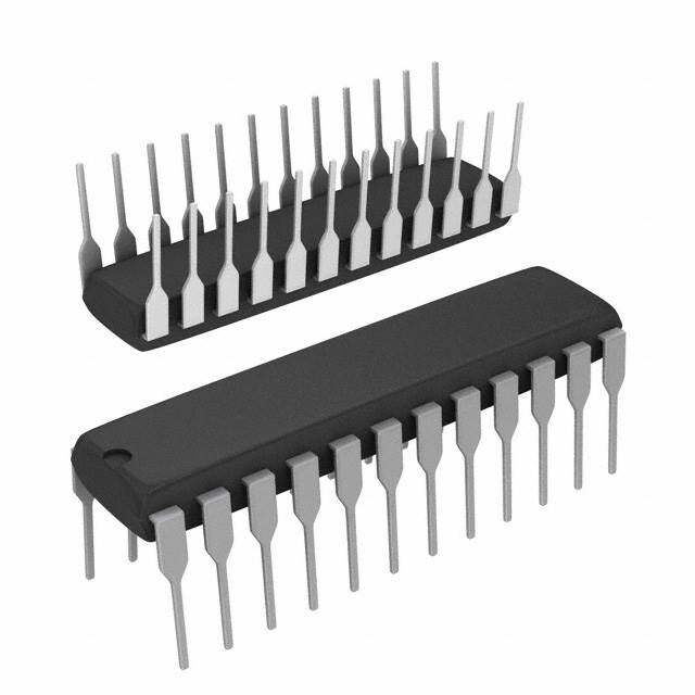
ICGOO电子元器件商城为您提供DAC0808LCN/NOPB由Texas Instruments设计生产,在icgoo商城现货销售,并且可以通过原厂、代理商等渠道进行代购。 DAC0808LCN/NOPB价格参考。Texas InstrumentsDAC0808LCN/NOPB封装/规格:数据采集 - 数模转换器, 8 位 数模转换器 1 16-PDIP。您可以下载DAC0808LCN/NOPB参考资料、Datasheet数据手册功能说明书,资料中有DAC0808LCN/NOPB 详细功能的应用电路图电压和使用方法及教程。
DAC0808LCN/NOPB 是由 Texas Instruments(德州仪器)生产的一款8位电压输出数模转换器(DAC)。它属于数据采集系统中的数模转换器类别,广泛应用于需要将数字信号转换为模拟信号的场景。以下是 DAC0808LCN/NOPB 的一些典型应用场景:

1. 工业控制:
   在工业自动化领域,DAC0808 可用于将数字控制信号转换为模拟信号,以驱动执行器、阀门或电机控制器。例如,调节温度控制系统中的加热元件电压或控制生产线上的机械臂动作。

2. 音频设备:
   该器件可用于简单的音频信号生成,例如合成波形或产生基础音调。尽管其分辨率仅为8位,可能不适用于高保真音频应用,但在低精度要求的场景中仍然实用。

3. 医疗设备:
   在某些医疗仪器中,如心电图(ECG)或脉搏血氧仪的校准模块,DAC0808 可以用来生成参考模拟信号,确保测量结果的准确性。

4. 测试与测量设备:
   用于生成可编程的测试信号,例如在示波器校准或信号发生器中提供标准电压输出。

5. 通信系统:
   在基础通信系统中,DAC0808 能够将数字编码的数据流转换为模拟信号,以便通过模拟信道传输信息。

6. 教育与科研:
   由于其简单易用且成本较低,DAC0808 常被用作教学工具,帮助学生理解数模转换的基本原理。同时,它也适合小型科研项目中的信号生成需求。

7. 消费电子产品:
   在早期的一些家用电子设备中,DAC0808 可能被用来实现基本的功能性模拟信号输出,例如亮度调节、对比度调整等。

需要注意的是,DAC0808 的性能相对有限,最大分辨率为8位,因此更适合对精度要求不高但注重成本和可靠性的应用场合。对于更高精度或更复杂的应用,可以考虑使用更先进的 DAC 器件。
| 参数 | 数值 |
| 产品目录 | 集成电路 (IC)半导体 |
| 描述 | IC CONVERTER D/A 8BIT 16-DIP数模转换器- DAC 8B A/D Cnvtr |
| 产品分类 | |
| 品牌 | Texas Instruments |
| 产品手册 | |
| 产品图片 |
|
| rohs | 符合RoHS无铅 / 符合限制有害物质指令(RoHS)规范要求 |
| 产品系列 | 数据转换器IC,数模转换器- DAC,Texas Instruments DAC0808LCN/NOPB- |
| 数据手册 | |
| 产品型号 | DAC0808LCN/NOPB |
| 产品目录页面 | |
| 产品种类 | 数模转换器- DAC |
| 位数 | 8 |
| 供应商器件封装 | 16-PDIP |
| 其它名称 | *DAC0808LCN/NOPB |
| 包装 | 管件 |
| 商标 | Texas Instruments |
| 安装类型 | 通孔 |
| 封装 | Tube |
| 封装/外壳 | 16-DIP(0.300",7.62mm) |
| 封装/箱体 | PDIP-16 |
| 工作温度 | 0°C ~ 75°C |
| 工厂包装数量 | 25 |
| 建立时间 | 150ns |
| 数据接口 | 并联 |
| 标准包装 | 25 |
| 电压源 | 双 ± |
| 系列 | DAC0808 |
| 转换器数 | 1 |
| 输出数和类型 | 1 电流,单极 |
| 采样率(每秒) | - |


PDF Datasheet 数据手册内容提取
DAC0808 DAC0808 8-Bit D/A Converter Literature Number: SNAS539A
D May1999 A C 0 8 0 8 DAC0808 8 - 8-Bit D/A Converter B i t General Description Features D The DAC0808 is an 8-bit monolithic digital-to-analog con- n Relativeaccuracy: ±0.19%errormaximum /A verter(DAC)featuringafullscaleoutputcurrentsettlingtime n Fullscalecurrentmatch: ±1LSBtyp of 150 ns while dissipating only 33 mW with ±5V supplies. n Fastsettlingtime:150nstyp C aNpoplriecafetiroennscesinccuerrtehnetf(uIlRlEsFc)alterimoumtpinugtciusrrreenqtuiisretdypficoarllmyo±s1t n NcoomnipnavteibrtliengdigitalinputsareTTLandCMOS on v LSB of 255 I /256. Relative accuracies of better than REF n Highspeedmultiplyinginputslewrate:8mA/µs e ±0.19% assure 8-bit monotonicity and linearity while zero n Powersupplyvoltagerange: ±4.5Vto ±18V r laecvceulraocuytpfuotrcIurre‡n2t mofAl.esTshethpaonw4erµsAuppprloyvicduersre8n-tsbitofzethroe n Lowpowerconsumption:33mW @ ±5V ter REF DAC0808 is independent of bit codes, and exhibits essen- tially constant device characteristics over the entire supply voltagerange. TheDAC0808willinterfacedirectlywithpopularTTL,DTLor CMOS logic levels, and is a direct replacement for the MC1508/MC1408. For higher speed applications, see DAC0800datasheet. Block and Connection Diagrams DS005687-1 Dual-In-LinePackage DS005687-2 TopView OrderNumberDAC0808 SeeNSPackageM16AorN16A ©2001NationalSemiconductorCorporation DS005687 www.national.com
8 0 8 Block and Connection Diagrams (Continued) 0 C A D Small-OutlinePackage DS005687-13 Ordering Information ACCURACY OPERATING TEMPERATURERANGE NPACKAGE(N16A) SOPACKAGE (Note1) (M16A) 8-bit 0˚C£ T £ +75˚C DAC0808LCN MC1408P8 DAC0808LCM A Note1: Devicesmaybeorderedbyusingeitherordernumber. www.national.com 2
D Absolute Maximum Ratings A (Note 2) StorageTemperatureRange −65˚Cto+150˚C C 0 If Military/Aerospace specified devices are required, LeadTemp.(Soldering,10seconds) 8 0 pleasecontacttheNationalSemiconductorSalesOffice/ Dual-In-LinePackage(Plastic) 260˚C 8 Distributorsforavailabilityandspecifications. Dual-In-LinePackage(Ceramic) 300˚C PowerSupplyVoltage SurfaceMountPackage V +18V VaporPhase(60seconds) 215˚C CC DC V −18V Infrared(15seconds) 220˚C EE DC DigitalInputVoltage,V5–V12 −10V to+18V DC DC Operating Ratings AppliedOutputVoltage,V −11V to+18V O DC DC ReferenceCurrent,I14 5mA TemperatureRange TMIN£ TA£ TMAX ReferenceAmplifierInputs,V14,V15 VCC,VEE DAC0808 0£ TA£ +75˚C PowerDissipation(Note4) 1000mW ESDSusceptibility(Note5) TBD Electrical Characteristics (V = 5V,V = −15V ,V /R14 = 2mA,andalldigitalinputsathighlogiclevelunlessotherwisenoted.) CC EE DC REF Symbol Parameter Conditions Min Typ Max Units E RelativeAccuracy(ErrorRelative (Figure4) % r toFullScaleI ) O DAC0808LC(LM1408-8) ±0.19 % SettlingTimetoWithin1⁄2LSB TA=25˚C(Note7), 150 ns (Includest ) (Figure5) PLH t ,t PropagationDelayTime T = 25˚C,(Figure5) 30 100 ns PLH PHL A TCI OutputFullScaleCurrentDrift ±20 ppm/˚C O MSB DigitalInputLogicLevels (Figure3) V HighLevel,Logic“1” 2 V IH DC V LowLevel,Logic“0” 0.8 V IL DC MSB DigitalInputCurrent (Figure3) HighLevel V = 5V 0 0.040 mA IH LowLevel V = 0.8V −0.003 −0.8 mA IL I ReferenceInputBiasCurrent (Figure3) −1 −3 µA 15 OutputCurrentRange (Figure3) V = −5V 0 2.0 2.1 mA EE V = −15V,T = 25˚C 0 2.0 4.2 mA EE A I OutputCurrent V = 2.000V, O REF R14 = 1000W , (Figure3) 1.9 1.99 2.1 mA OutputCurrent,AllBitsLow (Figure3) 0 4 µA OutputVoltageCompliance(Note3) E £ 0.19%,T = 25˚C r A V =−5V,I =1mA −0.55,+0.4 V EE REF DC V Below−10V −5.0,+0.4 V EE DC SRI ReferenceCurrentSlewRate (Figure6) 4 8 mA/µs REF OutputCurrentPowerSupply −5V£ V £ −16.5V 0.05 2.7 µA/V EE Sensitivity PowerSupplyCurrent(AllBits (Figure3) Low) I 2.3 22 mA CC I −4.3 −13 mA EE PowerSupplyVoltageRange T = 25˚C,(Figure3) A V 4.5 5.0 5.5 V CC DC V −4.5 −15 −16.5 V EE DC PowerDissipation 3 www.national.com
8 0 8 Electrical Characteristics (Continued) 0 C A (V = 5V,V = −15V ,V /R14 = 2mA,andalldigitalinputsathighlogiclevelunlessotherwisenoted.) CC EE DC REF D Symbol Parameter Conditions Min Typ Max Units AllBitsLow V = 5V,V = −5V 33 170 mW CC EE V = 5V,V = −15V 106 305 mW CC EE AllBitsHigh V = 15V,V = −5V 90 mW CC EE V = 15V,V = −15V 160 mW CC EE Note2: AbsoluteMaximumRatingsindicatelimitsbeyondwhichdamagetothedevicemayoccur.DCandACelectricalspecificationsdonotapplywhenoperating thedevicebeyonditsspecifiedoperatingconditions. Note3: Rangecontrolisnotrequired. Note4: ThemaximumpowerdissipationmustbederatedatelevatedtemperaturesandisdictatedbyTJMAX,q JA,andtheambienttemperature,TA.Themaximum allowablepowerdissipationatanytemperatureisPD=(TJMAX−TA)/q JAorthenumbergivenintheAbsoluteMaixmumRatings,whicheverislower.Forthisdevice, TJMAX=125˚C,andthetypicaljunction-to-ambientthermalresistanceofthedual-in-lineJpackagewhentheboardmountedis100˚C/W.Forthedual-in-lineN package,thisnumberincreasesto175˚C/WandforthesmalloutlineMpackagethisnumberis100˚C/W. Note5: Humanbodymodel,100pFdischargedthrougha1.5kW resistor. Note6: Allcurrentswitchesaretestedtoguaranteeatleast50%ofratedcurrent. Note7: Allbitsswitched. Note8: Pin-outnumbersfortheDAL080Xrepresentthedual-in-linepackage.Thesmalloutlinepackagepinoutdiffersfromthedual-in-linepackage. Typical Application DS005687-23 DS005687-3 FIGURE1.+10VOutputDigitaltoAnalogConverter(Note8) Typical Performance Characteristics V = 5V, V = −15V,T = 25˚C, unless otherwise noted CC EE A LogicInputCurrentvs BitTransferCharacteristics LogicThresholdVoltagevs InputVoltage Temperature DS005687-14 DS005687-15 DS005687-16 www.national.com 4
D Typical Performance Characteristics A VCC = 5V, VEE = −15V, TA = 25˚C, unless otherwise C noted (Continued) 0 8 0 8 OutputCurrentvsOutput OutputVoltageCompliance TypicalPowerSupply Voltage(OutputVoltage vsTemperature CurrentvsTemperature Compliance) DS005687-18 DS005687-17 DS005687-19 TypicalPowerSupply TypicalPowerSupply ReferenceInput CurrentvsVEE CurrentvsVCC FrequencyResponse DS005687-20 DS005687-21 DS005687-22 Unlessotherwisespecified:R14 = R15 = 1kW ,C = 15pF,pin16toV ;R = 50W ,pin4toground. EE L CurveA:LargeSignalBandwidthMethodofFigure7,V = 2Vp-poffset1Vaboveground. REF CurveB:SmallSignalBandwidthMethodofFigure7,R = 250W ,V = 50mVp-poffset200mVaboveground. L REF CurveC:LargeandSmallSignalBandwidthMethodofFigure9(noopamp,R =50W ),R =50W ,V =2V,V =100mVp-p L S REF S centeredat0V. 5 www.national.com
8 0 8 0 DAC S005687-4 D 8) e ot N ( s e ri e S 8 0 8 0 C A D e h t of uit c r Ci nt e al v ui q E 2. E R U G FI www.national.com 6
D Test Circuits A C 0 8 0 8 DS005687-6 VIandI1applytoinputsA1–A8. Theresistortiedtopin15istotemperaturecompensatethebiascurrentandmaynotbenecessaryforallapplications. andAN=“1”ifANisathighlevel AN=“0”ifANisatlowlevel FIGURE3.NotationDefinitionsTestCircuit(Note8) DS005687-7 FIGURE4.RelativeAccuracyTestCircuit(Note8) 7 www.national.com
8 0 8 Test Circuits (Continued) 0 C A D DS005687-8 FIGURE5.TransientResponseandSettlingTime(Note8) DS005687-9 FIGURE6.ReferenceCurrentSlewRateMeasurement(Note8) DS005687-10 FIGURE7.PositiveV (Note8) REF www.national.com 8
D Test Circuits A (Continued) C 0 8 0 8 DS005687-11 FIGURE8.NegativeV (Note8) REF DS005687-12 FIGURE9.ProgrammableGainAmplifieror DigitalAttenuatorCircuit(Note8) Application Hints For bipolar reference signals, as in the multiplying mode, R15canbetiedtoanegativevoltagecorrespondingtothe minimuminputlevel.ItispossibletoeliminateR15withonly REFERENCEAMPLIFIERDRIVEANDCOMPENSATION asmallsacrificeinaccuracyandtemperaturedrift. The reference amplifier provides a voltage at pin 14 for The compensation capacitor value must be increased with converting the reference voltage to a current, and a increasesinR14tomaintainproperphasemargin;forR14 turn-around circuit or current mirror for feeding the ladder. valuesof1,2.5and5kW ,minimumcapacitorvaluesare15, Thereferenceamplifierinputcurrrent,I ,mustalwaysflow 14 37 and 75 pF. The capacitor may be tied to either V or into pin 14, regardless of the set-up method or reference EE ground,butusingV increasesnegativesupplyrejection. voltagepolarity. EE A negative reference voltage may be used if R14 is Connections for a positive voltage are shown in Figure7. grounded and the reference voltage is applied to R15 as The reference voltage source supplies the full current I . 14 shown in Figure8. A high input impedance is the main 9 www.national.com
8 0 8 Application Hints (Continued) der.Thereferencecurrentmaydriftwithtemperature,caus- 0 C ing a change in the absolute accuracy of output current. A advantageofthismethod.Compensationinvolvesacapaci- However,theDAC0808hasaverylowfull-scalecurrentdrift D tor to V on pin 16, using the values of the previous withtemperature. EE paragraph.Thenegativereferencevoltagemustbeatleast The DAC0808 series is guaranteed accurate to within ±1⁄2 4V above the VEE supply. Bipolar input signals may be LSB at a full-scale output current of 1.992 mA. This corre- handled by connecting R14 to a positive reference voltage sponds to a reference amplifier output current drive to the equaltothepeakpositiveinputlevelatpin15. laddernetworkof2mA,withthelossof1LSB(8µA)which WhenaDCreferencevoltageisused,capacitivebypassto istheladderremaindershuntedtoground.Theinputcurrent groundisrecommended.The5Vlogicsupplyisnotrecom- topin14hasaguaranteedvalueofbetween1.9and2.1mA, mendedasareferencevoltage.Ifawellregulated5Vsupply allowingsomemismatchintheNPNcurrentsourcepair.The whichdriveslogicistobeusedasthereference,R14should accuracy test circuit is shown in Figure4. The 12-bit con- bedecoupledbyconnectingitto5Vthroughanotherresistor verter is calibrated for a full-scale output current of 1.992 andbypassingthejunctionofthe2resistorswith0.1µFto mA.ThisisanoptionalstepsincetheDAC0808accuracyis ground. For reference voltages greater than 5V, a clamp essentially the same between 1.5 and 2.5 mA. Then the diodeisrecommendedbetweenpin14andground. DAC0808 circuits’full-scale current is trimmed to the same Ifpin14isdrivenbyahighimpedancesuchasatransistor value with R14 so that a zero value appears at the error current source, none of the above compensation methods amplifieroutput.Thecounterisactivatedandtheerrorband apply and the amplifier must be heavily compensated, de- maybedisplayedonanoscilloscope,detectedbycompara- creasingtheoverallbandwidth. tors,orstoredinapeakdetector. Two8-bitD-to-Aconvertersmaynotbeusedtoconstructa OUTPUTVOLTAGERANGE 16-bit accuracy D-to-Aconverter. 16-bit accuracy implies a Thevoltageonpin4isrestrictedtoarangeof−0.55to0.4V totalerrorof±1⁄2ofonepartin65,536or±0.00076%,which when V = −5V due to the current switching methods ismuchmoreaccuratethanthe ±0.019%specificationpro- EE employedintheDAC0808. videdbytheDAC0808. ThenegativeoutputvoltagecomplianceoftheDAC0808is MULTIPLYINGACCURACY extendedto−5Vwherethenegativesupplyvoltageismore negative than −10V. Using a full-scale current of 1.992 mA The DAC0808 may be used in the multiplying mode with and load resistor of 2.5 kW between pin 4 and ground will 8-bit accuracy when the reference current is varied over a yieldavoltageoutputof256levelsbetween0and−4.980V. range of 256:1. If the reference current in the multiplying Floatingpin1doesnotaffecttheconverterspeedorpower mode ranges from 16 µA to 4 mA, the additional error dissipation. However, the value of the load resistor deter- contributions are less than 1.6 µA. This is well within 8-bit mines the switching time due to increased voltage swing. accuracywhenreferredtofull-scale. Values of R up to 500W do not significantly affect perfor- Amonotonicconverterisonewhichsuppliesanincreasein L mance,buta2.5kW loadincreasesworst-casesettlingtime currentforeachincrementinthebinaryword.Typically,the to 1.2 µs (when all bits are switched ON). Refer to the DAC0808 is monotonic for all values of reference current subsequenttextsectiononSettlingTimeformoredetailson above0.5mA.Therecommendedrangeforoperationwitha outputloading. DCreferencecurrentis0.5to4mA. OUTPUTCURRENTRANGE SETTLINGTIME Theoutputcurrentmaximumratingof4.2mAmaybeused Theworst-caseswitchingconditionoccurswhenallbitsare only for negative supply voltages more negative than −8V, switched ON, which corresponds to a low-to-high transition duetotheincreasedvoltagedropacrosstheresistorsinthe forallbits.Thistimeistypically150nsforsettlingtowithin referencecurrentamplifier. ±1⁄2LSB,for8-bitaccuracy,and100nsto1⁄2LSBfor7and 6-bitaccuracy.TheturnOFFistypicallyunder100ns.These ACCURACY timesapplywhenR £ 500W andC £ 25pF. L O Absolute accuracy is the measure of each output current Extracaremustbetakeninboardlayoutsincethisisusually level with respect to its intended value, and is dependent thedominantfactorinsatisfactorytestresultswhenmeasur- upon relative accuracy and full-scale current drift. Relative ing settling time. Short leads, 100 µF supply bypassing for accuracy is the measure of each output current level as a low frequencies, and minimum scope lead length are all fractionofthefull-scalecurrent.Therelativeaccuracyofthe mandatory. DAC0808isessentiallyconstantwithtemperatureduetothe excellenttemperaturetrackingofthemonolithicresistorlad- www.national.com 10
D Physical Dimensions A inches (millimeters) unless otherwise noted C 0 8 0 8 SmallOutlinePackage OrderNumberDAC0808LCM NSPackageNumberM16A Dual-In-LinePackage OrderNumberDAC0808 NSPackageNumberN16A 11 www.national.com
r e Notes t r e v n o C A / D t i B - 8 8 0 8 0 C A D LIFESUPPORTPOLICY NATIONAL’S PRODUCTS ARE NOT AUTHORIZED FOR USE AS CRITICAL COMPONENTS IN LIFE SUPPORT DEVICES OR SYSTEMS WITHOUT THE EXPRESS WRITTEN APPROVAL OF THE PRESIDENT AND GENERAL COUNSELOFNATIONALSEMICONDUCTORCORPORATION.Asusedherein: 1. Life support devices or systems are devices or 2. A critical component is any component of a life systems which, (a) are intended for surgical implant support device or system whose failure to perform into the body, or (b) support or sustain life, and can be reasonably expected to cause the failure of whose failure to perform when properly used in the life support device or system, or to affect its accordance with instructions for use provided in the safetyoreffectiveness. labeling, can be reasonably expected to result in a significantinjurytotheuser. NationalSemiconductor NationalSemiconductor NationalSemiconductor NationalSemiconductor Corporation Europe AsiaPacificCustomer JapanLtd. Americas Fax: +49(0)180-5308586 ResponseGroup Tel: 81-3-5639-7560 Email:support@nsc.com Email: europe.support@nsc.com Tel:65-2544466 Fax:81-3-5639-7507 Deutsch Tel: +49(0)6995086208 Fax:65-2504466 English Tel: +44(0)8702402171 Email:ap.support@nsc.com www.national.com FrançaisTel: +33(0)141918790 Nationaldoesnotassumeanyresponsibilityforuseofanycircuitrydescribed,nocircuitpatentlicensesareimpliedandNationalreservestherightatanytimewithoutnoticetochangesaidcircuitryandspecifications.
IMPORTANTNOTICE TexasInstrumentsIncorporatedanditssubsidiaries(TI)reservetherighttomakecorrections,modifications,enhancements,improvements, andotherchangestoitsproductsandservicesatanytimeandtodiscontinueanyproductorservicewithoutnotice.Customersshould obtainthelatestrelevantinformationbeforeplacingordersandshouldverifythatsuchinformationiscurrentandcomplete.Allproductsare soldsubjecttoTI’stermsandconditionsofsalesuppliedatthetimeoforderacknowledgment. TIwarrantsperformanceofitshardwareproductstothespecificationsapplicableatthetimeofsaleinaccordancewithTI’sstandard warranty.TestingandotherqualitycontroltechniquesareusedtotheextentTIdeemsnecessarytosupportthiswarranty.Exceptwhere mandatedbygovernmentrequirements,testingofallparametersofeachproductisnotnecessarilyperformed. TIassumesnoliabilityforapplicationsassistanceorcustomerproductdesign.Customersareresponsiblefortheirproductsand applicationsusingTIcomponents.Tominimizetherisksassociatedwithcustomerproductsandapplications,customersshouldprovide adequatedesignandoperatingsafeguards. TIdoesnotwarrantorrepresentthatanylicense,eitherexpressorimplied,isgrantedunderanyTIpatentright,copyright,maskworkright, orotherTIintellectualpropertyrightrelatingtoanycombination,machine,orprocessinwhichTIproductsorservicesareused.Information publishedbyTIregardingthird-partyproductsorservicesdoesnotconstitutealicensefromTItousesuchproductsorservicesora warrantyorendorsementthereof.Useofsuchinformationmayrequirealicensefromathirdpartyunderthepatentsorotherintellectual propertyofthethirdparty,oralicensefromTIunderthepatentsorotherintellectualpropertyofTI. ReproductionofTIinformationinTIdatabooksordatasheetsispermissibleonlyifreproductioniswithoutalterationandisaccompanied byallassociatedwarranties,conditions,limitations,andnotices.Reproductionofthisinformationwithalterationisanunfairanddeceptive businesspractice.TIisnotresponsibleorliableforsuchaltereddocumentation.Informationofthirdpartiesmaybesubjecttoadditional restrictions. ResaleofTIproductsorserviceswithstatementsdifferentfromorbeyondtheparametersstatedbyTIforthatproductorservicevoidsall expressandanyimpliedwarrantiesfortheassociatedTIproductorserviceandisanunfairanddeceptivebusinesspractice.TIisnot responsibleorliableforanysuchstatements. TIproductsarenotauthorizedforuseinsafety-criticalapplications(suchaslifesupport)whereafailureoftheTIproductwouldreasonably beexpectedtocauseseverepersonalinjuryordeath,unlessofficersofthepartieshaveexecutedanagreementspecificallygoverning suchuse.Buyersrepresentthattheyhaveallnecessaryexpertiseinthesafetyandregulatoryramificationsoftheirapplications,and acknowledgeandagreethattheyaresolelyresponsibleforalllegal,regulatoryandsafety-relatedrequirementsconcerningtheirproducts andanyuseofTIproductsinsuchsafety-criticalapplications,notwithstandinganyapplications-relatedinformationorsupportthatmaybe providedbyTI.Further,BuyersmustfullyindemnifyTIanditsrepresentativesagainstanydamagesarisingoutoftheuseofTIproductsin suchsafety-criticalapplications. TIproductsareneitherdesignednorintendedforuseinmilitary/aerospaceapplicationsorenvironmentsunlesstheTIproductsare specificallydesignatedbyTIasmilitary-gradeor"enhancedplastic."OnlyproductsdesignatedbyTIasmilitary-grademeetmilitary specifications.BuyersacknowledgeandagreethatanysuchuseofTIproductswhichTIhasnotdesignatedasmilitary-gradeissolelyat theBuyer'srisk,andthattheyaresolelyresponsibleforcompliancewithalllegalandregulatoryrequirementsinconnectionwithsuchuse. TIproductsareneitherdesignednorintendedforuseinautomotiveapplicationsorenvironmentsunlessthespecificTIproductsare designatedbyTIascompliantwithISO/TS16949requirements.Buyersacknowledgeandagreethat,iftheyuseanynon-designated productsinautomotiveapplications,TIwillnotberesponsibleforanyfailuretomeetsuchrequirements. FollowingareURLswhereyoucanobtaininformationonotherTexasInstrumentsproductsandapplicationsolutions: Products Applications Audio www.ti.com/audio CommunicationsandTelecom www.ti.com/communications Amplifiers amplifier.ti.com ComputersandPeripherals www.ti.com/computers DataConverters dataconverter.ti.com ConsumerElectronics www.ti.com/consumer-apps DLP®Products www.dlp.com EnergyandLighting www.ti.com/energy DSP dsp.ti.com Industrial www.ti.com/industrial ClocksandTimers www.ti.com/clocks Medical www.ti.com/medical Interface interface.ti.com Security www.ti.com/security Logic logic.ti.com Space,AvionicsandDefense www.ti.com/space-avionics-defense PowerMgmt power.ti.com TransportationandAutomotive www.ti.com/automotive Microcontrollers microcontroller.ti.com VideoandImaging www.ti.com/video RFID www.ti-rfid.com OMAPMobileProcessors www.ti.com/omap WirelessConnectivity www.ti.com/wirelessconnectivity TIE2ECommunityHomePage e2e.ti.com MailingAddress:TexasInstruments,PostOfficeBox655303,Dallas,Texas75265 Copyright©2011,TexasInstrumentsIncorporated

 Datasheet下载


