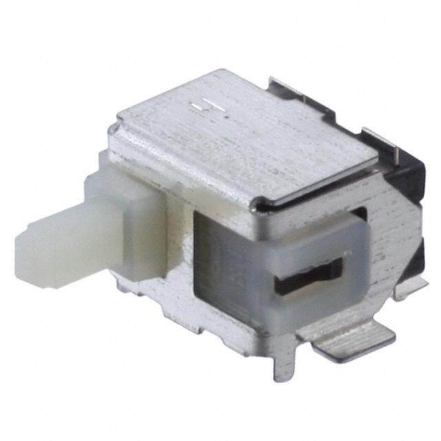
- 型号: D3SK-B1L
- 制造商: Omron Electronics LLC
- 库位|库存: xxxx|xxxx
- 要求:
| 数量阶梯 | 香港交货 | 国内含税 |
| +xxxx | $xxxx | ¥xxxx |
查看当月历史价格
查看今年历史价格
D3SK-B1L产品简介:
ICGOO电子元器件商城为您提供D3SK-B1L由Omron Electronics LLC设计生产,在icgoo商城现货销售,并且可以通过原厂、代理商等渠道进行代购。 D3SK-B1L价格参考。Omron Electronics LLCD3SK-B1L封装/规格:快动,限位开关, 。您可以下载D3SK-B1L参考资料、Datasheet数据手册功能说明书,资料中有D3SK-B1L 详细功能的应用电路图电压和使用方法及教程。
| 参数 | 数值 |
| 产品目录 | |
| 描述 | SWITCH DETECT SPST-NC LEFT 5V |
| 产品分类 | |
| 品牌 | Omron Electronics Inc-EMC Div |
| 数据手册 | |
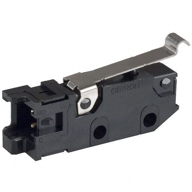
| 产品图片 |
|
| 产品型号 | D3SK-B1L |
| rohs | 无铅 / 符合限制有害物质指令(RoHS)规范要求 |
| 产品系列 | D3SK |
| 侵入防护 | - |
| 其它名称 | SW1543CT |
| 其它有关文件 | |
| 包装 | 剪切带 (CT) |
| 安装类型 | 表面贴装,直角 |
| 工作位置 | 0.185" (4.7mm) |
| 工作温度 | -25°C ~ 85°C |
| 差动行程 | - |
| 开关功能 | 开-瞬时 |
| 操作力,扭矩 | 41gf |
| 机械寿命 | 150,000 次循环 |
| 标准包装 | 1 |
| 特性 | 板导轨,左操纵杆 |
| 电气寿命 | 100,000 次循环 |
| 电路 | SPST-NC |
| 端子类型 | 鸥翼型 |
| 致动器类型 | 角拨动开关(检测器) |
| 超行程 | - |
| 释放力 | - |
| 预行程 | - |
| 额定电压-AC | - |
| 额定电压-DC | 5V |
| 额定电流 | 1mA(DC) |



PDF Datasheet 数据手册内容提取
D3SK Surface Mount Switch The smallest detection switch in the industry with high precision operation. (OMRON's data as of April 2008) (3.0 × 3.5 × 0.9 mm (W × D × H)) D 3 S ●Ultra small size and ultra low profile contributing K to down-sizing of sets devices. ●A unique mechanism enables high contact reliability and high precision operation. ●Long stroke improves easy installation. ●Meet a variety of applications by contact and lever variations. RoHS Compliant Model Number Legend Contact Form D3SK @1 @2@3 @4 ●SPST-NO 1. Contact form 3. Lever and Direction of Operation A: SPST-NO R: Right operating lever COM N.O COM N.O B: SPST-NC L: Left operating lever 2. Boss of Positioning 4. Packaging Specifications 0: without Boss None : 1,000 pcs. ●SPST-NC 1: with Boss -6 : 6,000 pcs. COM N.C COM N.C Note.The cover has the same electric potential as the COM terminal. List of Models Contact Specifications Direction of Operation Boss of Positioning Model Packing form* D3SK-A1R 1,000 pcs. With Boss D3SK-A1R-6 6,000 pcs. Right D3SK-A0R 1,000 pcs. Without Boss D3SK-A0R-6 6,000 pcs. SPST-NO D3SK-A1L 1,000 pcs. With Boss D3SK-A1L-6 6,000 pcs. Left D3SK-A0L 1,000 pcs. Without Boss D3SK-A0L-6 6,000 pcs. D3SK-B1R 1,000 pcs. With Boss D3SK-B1R-6 6,000 pcs. Right D3SK-B0R 1,000 pcs. Without Boss D3SK-B0R-6 6,000 pcs. SPST-NC D3SK-B1L 1,000 pcs. With Boss D3SK-B1L-6 6,000 pcs. Left D3SK-B0L 1,000 pcs. Without Boss D3SK-B0L-6 6,000 pcs. * Products are packed with embossed tape. 1
D3SK Surface Mount Switch Contact Specifications Ratings Contact Specifications Slide Rated voltage Resistive load Minimum applicable load 15 μA at 3 VDC 5 VDC 1 mA Note.The above rating values apply under the following test conditions. (1) Ambient temperature: 20±2°C (2) Ambient humidity: 65±5% (3) Operating frequency: 20 operations/min Characteristics D Permissible operating speed 1 to 300 mm/s 3 Permissible operating Mechanical 60 operations/min S K frequency Electrical 60 operations/min Insulation resistance 100 MΩ min. (at 100 VDC with insulation tester) Contact resistance (initial value) 3 Ω min. Dielectric strength Between terminals of the same polarity 100 VAC (50/60 Hz for 1 min) Vibration resistance *1 Malfunction 10 to 55 Hz, 1.5 mm double amplitude Durability 1000 m/s2 {approx. 100G} max. Shock resistance Malfunction *1 300 m/s2 {approx. 30G} max. Mechanical 150,000 operations min. (20 operations/min) Durability *2 Electrical 100,000 operations min. (20 operations/min) Ambient operating temperature -25 to +85°C (at ambient humidity 60% max.) (with no icing or condensation) Ambient operating humidity 85% max. (for +5 to +35°C) Weight Approx. 0.02 g Note.The data given above are initial values. *1. The given values apply for Total Travel Position. Close or open circuit of the contact is 1 ms max. *2. For testing conditions, consult your OMRON sales representative. Dimensions (Unit: mm) and Operating Characteristics The @ is replaced with the code for the contact form that you need. See the "List of Models" for available combinations of models. Model D3SK-@@R Operating Characteristics D3SK-@@L Operating Force OF Max. 0.4 N {41 gf} Free Position FP 4.95±0.15 mm Operating Position OP 4.7±0.2 mm Total Travel Position TTP 3.5±0.2 mm ●Right operating - without Boss D3SK-@0R A (0.8) 1.4 PCB land dimensions (reference) (0.46)Center of rotation 1.1 (TOP VIEW) B Center of rotation 3.10.8 0.250.41.65 Total Travel Position Operating Position Free Position 1.1 00..4515.65 3 0.39 2.2 0.9±0.05 4.4 0.5 0.36 Note 1.Unless otherwise specified, a tolerance of ±0.15 mm applies to all dimensions described in the above figure. Note 2.The operating characteristics are for operation in the A direction () and B direction (, ) has the same operation characteristic values as of the A direction. 2
D3SK Surface Mount Switch ●Left operating - without Boss D3SK-@0L A (0.8) PCB land dimensions (reference) (0.46) 1.4 Center of rotation 1.1 (TOP VIEW) B Center of rotation Free Position Operating Position Total Travel Position 0.8 0.25 0.41.653.1 1.1 00..4515.65 DS3 K 3 0.39 2.2 0.9±0.05 4.4 0.5 0.37 ●Right operating - with Boss D3SK-@1R A PCB mounting hole and land dimensions (reference) (0.8) (0.46)Center of rotation 1.1 1.4 (TOP VIEW) 0.4 B Center of rotation 2-0.7 + . 00 5 dia. 02.±60±.10C.005. 1d5ia. 3.10.8 0.250.41.65 Total Travel Position Operating Position Free Position 2.82±0.05 1.1 00..4515.65 0.9±0.05 0.39 3 24..24 0.5 0.37 ●Left operating - with Boss D3SK-@1L A (0.8) PCB mounting hole and land dimensions (reference) (0.46) 1.4 Center of rotation 1.1 (TOP VIEW) 0.4 B Center of rotation 2-0.7 + 0 0 . 0 5 dia. 02.6±0±C.01.005. 1d5ia. Free Position Operating Position Total Travel Position 0.8 0.25 0.41.653.1 2.82±0.051.1 00..4551.7 3 2.2 0.39 4.4 0.9±0.05 0.5 0.37 Note 1.Unless otherwise specified, a tolerance of ±0.15 mm applies to all dimensions described in the above figure. Note 2.The operating characteristics are for operation in the A direction () and B direction (, ) has the same operation characteristic values as of the A direction. Packaging Specifications Standards Conforms to JEITA 1.50+ 00.10dia. holes 2 4±0.1 Tape, carrier (1.8) (19) Label Feed direction Package QQttyy 16,,000000 ppccss..//rreeeell 8±0.1 1.8±0.1 6.9 12±0.30 Drawing direction Standard package Qty: 1,000 pcs./reel Reel 13 dia. 380 dia. 6,000 pcs./reel 3
D3SK Surface Mount Switch Precautions ★Please refer to "Common Precautions" for correct use. Caution Correct Use ●Electrical Ratings ●Mounting (cid:129)Confirm the contact load in order to select an appropriate (cid:129)The cover has the same electric potential as the COM switch rating. terminal. Do not short-circuit the cover with a NO or NC (cid:129)Do not apply an excessive electrical load to the contacts, terminal when mounting the cover. otherwise the contacts may weld, resulting in a short circuit or D burning. Cover 3 ●Terminal Connection S K (cid:129)Do not use flow soldering or hand soldering to solder terminals. (cid:129)Be careful of the following points. Incorrect handling may lead (cid:129)Conduct reflow soldering within the range shown in the to insufficient actuator return, Switch damage, or reduced terminal temperature profile below. durability. Some reflow soldering devices have extremely high peak - Set the operating body in line with the direction of the values. Do a test in advance to confirm proper soldering actuator movement, and make sure that the operating conditions. body is completely separate from the actuator when the (cid:129)Do not conduct reflow soldering more than twice. Also provide Switch is in the free position (FP). When the actuator is a time interval of at least five minutes between the first and operated from the crosswise direction of the Switch, make second reflow soldering processes to allow the Switch to sure that the corner of the operating body has a minimum return to room temperature. radius of R1. Heating the Switch continuously (without an interval) may cause the edges of the Switch to melt and degrade the characteristics. R1 min. (cid:129)When printing for a cream solder process, a 0.13 mm screen thickness is recommended. (cid:129)Be sure to provide local ventilation. Operating body MAX255°C - Set the Switch stroke to 70% to 100% of the overtravel 220°C (the difference between the operating position and the 180°C total travel position). 150°C - Do not subject the Switch to operations that involve strong impact. - Do not use the Switch as a stopper. - Do not apply excessive loads to the cover or operate the Preheating time Heating time actuator from a direction other than a specified operating 90 to 120 s 40 s max. direction. ●Printed Circuit Boards - Do not use an adhesive to secure the Switch. (cid:129)A lubricant is used in the Switch. Some of the lubricant may Special attention must be paid to the handling of printed circuit seep out because the Switch does not have an airtight boards after a Switch has been mounted onto them. Airborne construction. Consider this possibility with respect to the PCB particles may penetrate the interior of the Switch when usage conditions when designing or using the Switch. printed circuit boards are separated by cutting. Also, do not stack printed circuit boards that have Switches mounted on them. ●Application Environment (cid:129)Do not use the Switch in locations that are subject to toxic gas, ●Product Specification Details silicon gas, excessive dust, excessive dirt, high temperatures, This document provides only a partial list of specifications. It is high humidity, sudden temperature changes, water splashes, recommended that you request complete drawings and or oil splashes. specifications prior to purchasing or using the product. (cid:129)Otherwise, damage resulting by faulty contact of the Switch contacts, corrosion, or other causes, or other functional faults may occur. ●Insulation and Wiring Be sure that the installation conditions provide a sufficient insulation distance between Switch terminals and other metal parts, lands, etc. ●Cleaning The Switch does not have an airtight construction, and it must not be cleaned with cleaning fluids. Malfunctions may occur if the cleaning fluid penetrates the interior of the Switch together with flux or foreign matter from the surface of the PCB. ●Confirmation with Actual Equipment Be sure to confirm the quality of the product under the load and environmental conditions that will be used during actual applications. 4
D3SK Surface Mount Switch D 3 S K (cid:129) Application examples provided in this document are for reference only. In actual applications, confirm equipment functions and safety before using the product. (cid:129) Consult your OMRON representative before using the product under conditions which are not described in the manual or applying the product to nuclear control systems, railroad systems, aviation systems, vehicles, combustion systems, medical equipment, amusement machines, safety equipment, and other systems or equipment that may have a serious influence on lives and property if used improperly. Make sure that the ratings and performance characteristics of the product provide a margin of safety for the system or equipment, and be sure to provide the system or equipment with double safety mechanisms. Note: Do not use this document to operate the Unit. OMRON Corporation ELECTRONIC AND MECHANICAL COMPONENTS COMPANY Contact: www.omron.com/ecb Cat. No.B115-E1-03 1113(0207)(O) 5

 Datasheet下载


