
 Datasheet下载
- 型号: CY7C1461AV33-133AXC
- 制造商: Cypress Semiconductor
- 库位|库存: xxxx|xxxx
- 要求:
| 数量阶梯 | 香港交货 | 国内含税 |
| +xxxx | $xxxx | ¥xxxx |
查看当月历史价格
查看今年历史价格
CY7C1461AV33-133AXC产品简介:
ICGOO电子元器件商城为您提供CY7C1461AV33-133AXC由Cypress Semiconductor设计生产,在icgoo商城现货销售,并且可以通过原厂、代理商等渠道进行代购。 CY7C1461AV33-133AXC价格参考。Cypress SemiconductorCY7C1461AV33-133AXC封装/规格:存储器, SRAM - 同步 存储器 IC 36Mb (1M x 36) 并联 133MHz 6.5ns 100-TQFP(14x20)。您可以下载CY7C1461AV33-133AXC参考资料、Datasheet数据手册功能说明书,资料中有CY7C1461AV33-133AXC 详细功能的应用电路图电压和使用方法及教程。
| 参数 | 数值 |
| 产品目录 | 集成电路 (IC)半导体 |
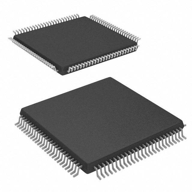
| 描述 | IC SRAM 36MBIT 133MHZ 100TQFP静态随机存取存储器 36Mb 3.3V 133Mhz 1Mx36 Flow-Thru 静态随机存取存储器 |
| 产品分类 | |
| 品牌 | Cypress Semiconductor Corp |
| 产品手册 | |
| 产品图片 |
|
| rohs | 符合RoHS无铅 / 符合限制有害物质指令(RoHS)规范要求 |
| 产品系列 | 内存,静态随机存取存储器,Cypress Semiconductor CY7C1461AV33-133AXCNoBL™ |
| 数据手册 | http://www.cypress.com/?docID=38529 |
| 产品型号 | CY7C1461AV33-133AXC |
| PCN组件/产地 | http://www.cypress.com/?docID=47158http://www.cypress.com/?docID=48115http://www.cypress.com/?docID=49741 |
| 产品种类 | 静态随机存取存储器 |
| 供应商器件封装 | 100-TQFP(14x20) |
| 其它名称 | 428-3251 |
| 包装 | 托盘 |
| 商标 | Cypress Semiconductor |
| 存储器类型 | SRAM - 同步 |
| 存储容量 | 36M(1M x 36) |
| 存储类型 | SDR |
| 安装风格 | SMD/SMT |
| 封装 | Tray |
| 封装/外壳 | 100-LQFP |
| 封装/箱体 | TQFP-100 |
| 工作温度 | 0°C ~ 70°C |
| 工厂包装数量 | 72 |
| 接口 | 并联 |
| 最大工作温度 | + 70 C |
| 最大工作电流 | 310 mA |
| 最大时钟频率 | 133 MHz |
| 最小工作温度 | 0 C |
| 标准包装 | 72 |
| 格式-存储器 | RAM |
| 电压-电源 | 2.375 V ~ 3.6 V |
| 电源电压-最大 | 3.6 V |
| 电源电压-最小 | 3.135 V |
| 类型 | Synchronous |
| 系列 | CY7C1461AV33 |
| 组织 | 1 M x 36 |
| 访问时间 | 6.5 ns |
| 速度 | 133MHz |


- 商务部:美国ITC正式对集成电路等产品启动337调查
- 曝三星4nm工艺存在良率问题 高通将骁龙8 Gen1或转产台积电
- 太阳诱电将投资9.5亿元在常州建新厂生产MLCC 预计2023年完工
- 英特尔发布欧洲新工厂建设计划 深化IDM 2.0 战略
- 台积电先进制程称霸业界 有大客户加持明年业绩稳了
- 达到5530亿美元!SIA预计今年全球半导体销售额将创下新高
- 英特尔拟将自动驾驶子公司Mobileye上市 估值或超500亿美元
- 三星加码芯片和SET,合并消费电子和移动部门,撤换高东真等 CEO
- 三星电子宣布重大人事变动 还合并消费电子和移动部门
- 海关总署:前11个月进口集成电路产品价值2.52万亿元 增长14.8%


PDF Datasheet 数据手册内容提取
Please note that Cypress is an Infineon Technologies Company. The document following this cover page is marked as “Cypress” document as this is the company that originally developed the product. Please note that Infineon will continue to offer the product to new and existing customers as part of the Infineon product portfolio. Continuity of document content The fact that Infineon offers the following product as part of the Infineon product portfolio does not lead to any changes to this document. Future revisions will occur when appropriate, and any changes will be set out on the document history page. Continuity of ordering part numbers Infineon continues to support existing part numbers. Please continue to use the ordering part numbers listed in the datasheet for ordering. www.infineon.com
THIS SPEC IS OBSOLETE Spec No: 38-05 356 Spec Title: C Y7C 1461AV33/CY7C1463AV33, 36-MBIT (1M X 36/2M X 18) FLOW-THROUGH SRAM WITH NOBL(TM) ARCHITECTURE Replaced by: None
CY7C1461AV33 CY7C1463AV33 36-Mbit (1M × 36/2M × 18) Flow-Through SRAM with NoBL™ Architecture 336-Mbit (1M × 36/2M × 18) Flow-Through SRAM with NoBL™ Architecture Features Functional Description ■No Bus Latency™ (NoBL™) architecture eliminates dead The CY7C1461AV33/CY7C1463AV33 are 3.3V, cycles between write and read cycles 1M×36/2M×18 Synchronous Flow-Through Burst SRAMs designed specifically to support unlimited true back-to-back read ■Supports up to 133 MHz bus operations with zero wait states and write operations without the insertion of wait states. The ❐Data is transferred on every clock CY7C1461AV33/CY7C1463AV33 is equipped with the advanced NoBL logic required to enable consecutive read and write ■Pin compatible and functionally equivalent to ZBT™ devices operations with data being transferred on every clock cycle. This ■Internally self timed output buffer control to eliminate the need feature dramatically improves the throughput of data through the to use OE SRAM, especially in systems that require frequent write-read transitions. ■Registered inputs for flow through operation All synchronous inputs pass through input registers controlled by ■Byte write capability the rising edge of the clock. The clock input is qualified by the ■3.3 V and 2.5 V I/O power supply Clock Enable (CEN) signal, which when deasserted suspends operation and extends the previous clock cycle. Maximum ■Fast clock-to-output times access delay from the clock rise is 6.5 ns (133 MHz device). ❐6.5 ns (for 133 MHz device) Write operations are controlled by the two or four Byte Write ■Clock Enable (CEN) pin to enable clock and suspend operation Select (BWX) and a Write Enable (WE) input. All writes are conducted with on-chip synchronous self timed write circuitry. ■Synchronous self timed writes Three synchronous Chip Enables (CE , CE , CE ) and an 1 2 3 ■Asynchronous Output Enable asynchronous Output Enable (OE) provide for easy bank selection and output tri-state control. To avoid bus contention, ■CY7C1461AV33, CY7C1463AV33 available in the output drivers are synchronously tri-stated during the data JEDEC-standard Pb-free 100-pin TQFP package. portion of a write sequence. ■Three chip enables for simple depth expansion For a complete list of related documentation, click here. ■Automatic power down feature available using ZZ mode or CE deselect ■Burst capability – linear or interleaved burst order ■Low standby power Selection Guide Description 133 MHz Unit Maximum Access Time 6.5 ns Maximum Operating Current 310 mA Maximum CMOS Standby Current 120 mA CypressSemiconductorCorporation • 198 Champion Court • SanJose, CA 95134-1709 • 408-943-2600 Document Number: 38-05356 Rev. *O Revised July 26, 2016
CY7C1461AV33 CY7C1463AV33 Logic Block Diagram – CY7C1461AV33 A0, A1, A ADDRESS REGISTER A1 D1 Q1 A1' A0 A0' MODE D0 Q0 BURST CLK C CE ADV/LD LOGIC CEN C WRITE ADDRESS REGISTER O U T D P S A U E T T ADV/LD N A BWA WRITE REGISTRY WRITE MAERMROARYY ES S UB DQs BBWWBC ANDC DOANTTAR OCLO HLOERGEICNCY DRIVERS MA TEE EFF DDQQPPAB BWD PS RI RS DDQQPPCD WE N E G INPUT E REGISTER OE READ LOGIC CE1 CE2 CE3 SLEEP ZZ CONTROL Document Number: 38-05356 Rev. *O Page 2 of 24
CY7C1461AV33 CY7C1463AV33 Logic Block Diagram – CY7C1463AV33 A0, A1, A ADDRESS REGISTER A1 D1 Q1 A1' A0 A0' MODE D0 Q0 BURST CLK C CE ADV/LD LOGIC CEN C WRITE ADDRESS REGISTER O U T D P S A U E T T ADV/LD N A MEMORY S B BWA WRITE REGISTRY WRITE ARRAY E S U DQs BWB ANDC ODNATTARO CLO LHOEGRIECNCY DRIVERS MA TEE EFF DDQQPPAB P R R S I S WE N E G INPUT E REGISTER OE READ LOGIC CE1 CE2 CE3 ZZ SLEEP CONTROL Document Number: 38-05356 Rev. *O Page 3 of 24
CY7C1461AV33 CY7C1463AV33 Contents Pin Configurations ...........................................................5 Thermal Resistance ........................................................13 Pin Definitions ..................................................................7 AC Test Loads and Waveforms .....................................13 Functional Overview ........................................................8 Switching Characteristics ..............................................14 Single Read Accesses ................................................8 Switching Waveforms ....................................................15 Burst Read Accesses ..................................................8 Ordering Information ......................................................18 Single Write Accesses .................................................8 Ordering Code Definitions .........................................18 Burst Write Accesses ..................................................8 Package Diagrams ..........................................................19 Sleep Mode .................................................................9 Acronyms ........................................................................20 Interleaved Burst Address Table .................................9 Document Conventions .................................................20 Linear Burst Address Table .........................................9 Units of Measure .......................................................20 ZZ Mode Electrical Characteristics ..............................9 Document History Page .................................................21 Truth Table ......................................................................10 Sales, Solutions, and Legal Information ......................24 Truth Table for Read/Write ............................................11 Worldwide Sales and Design Support .......................24 Truth Table for Read/Write ............................................11 Products ....................................................................24 Maximum Ratings ...........................................................12 PSoC® Solutions ......................................................24 Operating Range .............................................................12 Cypress Developer Community .................................24 Electrical Characteristics ...............................................12 Technical Support .....................................................24 Capacitance ....................................................................13 Document Number: 38-05356 Rev. *O Page 4 of 24
CY7C1461AV33 CY7C1463AV33 Pin Configurations Figure 1. 100-pin TQFP (14 × 20 × 1.4 mm) pinout D L A A CE1 CE2 BWD BWC BWB BWA CE3 VDD VSS CLK WE CEN OE ADV/ A A A A 0 0 9 8 7 6 5 4 3 2 1 0 9 8 7 6 5 4 3 2 1 1 9 9 9 9 9 9 9 9 9 9 8 8 8 8 8 8 8 8 8 DQPC 1 80 DQPB DQC 2 79 DQB DQC 3 78 DQB VDDQ 4 77 VDDQ VSS 5 76 VSS BYTE C DQC 6 75 DQB DQC 7 74 DQB BYTE B DQC 8 73 DQB DQC 9 72 DQB VSS 10 71 VSS VDDQ 11 70 VDDQ DQC 12 69 DQB DQC 13 68 DQB NC 14 67 V SS VDD 15 CY7C1461AV33 66 NC NC 16 65 V DD VSS 17 64 ZZ DQD 18 63 DQA DQD 19 62 DQA VDDQ 20 61 VDDQ VSS 21 60 VSS BYTE D DQD 22 59 DQA DQD 23 58 DQA DQD 24 57 DQA BYTE A DQD 25 56 DQA VSS 26 55 VSS VDDQ 27 54 VDDQ DQD 28 53 DQA DQD 29 52 DQA DQPD 30 51 DQPA 1 2 3 4 5 6 7 8 9 0 1 2 3 4 5 6 7 8 9 0 3 3 3 3 3 3 3 3 3 4 4 4 4 4 4 4 4 4 4 5 ODE A A A A A1 A0 88M 44M VSS VDD 72M A A A A A A A A M C/2 C/1 NC/ N N Document Number: 38-05356 Rev. *O Page 5 of 24
CY7C1461AV33 CY7C1463AV33 Pin Configurations (continued) Figure 2. 100-pin TQFP (14 × 20 × 1.4 mm) pinout D L A A CE1 CE2 NC NC BWB BWA CE3 VDD VSS CLK WE CEN OE ADV/ A A A A 0 0 9 8 7 6 5 4 3 2 1 0 9 8 7 6 5 4 3 2 1 1 9 9 9 9 9 9 9 9 9 9 8 8 8 8 8 8 8 8 8 NC 1 80 A NC 2 79 NC NC 3 78 NC VDDQ 4 77 VDDQ VSS 5 76 VSS NC 6 75 NC NC 7 74 DQP A DQB 8 73 DQA DQB 9 72 DQA VSS 10 71 VSS VDDQ 11 70 VDDQ DQB 12 69 DQA DQB 13 68 DQA BYTE A NC 14 67 V SS VDD 15 CY7C1463AV33 66 NC BYTE B NC 16 65 V DD VSS 17 64 ZZ DQB 18 63 DQA DQB 19 62 DQA VDDQ 20 61 VDDQ VSS 21 60 VSS DQB 22 59 DQA DQB 23 58 DQA DQPB 24 57 NC NC 25 56 NC VSS 26 55 VSS VDDQ 27 54 VDDQ NC 28 53 NC NC 29 52 NC NC 30 51 NC 1 2 3 4 5 6 7 8 9 0 1 2 3 4 5 6 7 8 9 0 3 3 3 3 3 3 3 3 3 4 4 4 4 4 4 4 4 4 4 5 DE A A A A A1 A0 M M VSS VDD M A A A A A A A A O 8 4 2 M C/28 C/14 NC/7 N N Document Number: 38-05356 Rev. *O Page 6 of 24
CY7C1461AV33 CY7C1463AV33 Pin Definitions Pin Name I/O Description A , A , A Input- Address Inputs. Used to select one of the address locations. Sampled at the rising edge of the CLK. 0 1 Synchronous A are fed to the two-bit burst counter. [1:0] BWA, BWB, Input- Byte Write Inputs, Active LOW. Qualified with WE to conduct writes to the SRAM. Sampled on the BW , BW Synchronous rising edge of CLK. C D WE Input- Write Enable Input, Active LOW. Sampled on the rising edge of CLK if CEN is active LOW. This signal Synchronous must be asserted LOW to initiate a write sequence. ADV/LD Input- Advance or Load Input. Used to advance the on-chip address counter or load a new address. When Synchronous HIGH (and CEN is asserted LOW) the internal burst counter is advanced. When LOW, a new address can be loaded into the device for an access. After deselecting, drive ADV/LD LOW to load a new address. CLK Input- Clock Input. Used to capture all synchronous inputs to the device. CLK is qualified with CEN. CLK is Clock only recognized if CEN is active LOW. CE Input- Chip Enable 1 Input, Active LOW. Sampled on the rising edge of CLK. Used in conjunction with CE 1 2 Synchronous and CE to select or deselect the device. 3 CE Input- Chip Enable 2 Input, Active HIGH. Sampled on the rising edge of CLK. Used in conjunction with CE 2 1 Synchronous and CE to select or deselect the device. 3 CE Input- Chip Enable 3 Input, Active LOW. Sampled on the rising edge of CLK. Used in conjunction with CE 3 1 Synchronous andCE to select or deselect the device. 2 OE Input- Output Enable, Asynchronous Input, Active LOW. Combined with the synchronous logic block inside Asynchronous the device to control the direction of the I/O pins. When LOW, the I/O pins are allowed to behave as outputs. When deasserted HIGH, I/O pins are tri-stated and act as input data pins. OE is masked during the data portion of a write sequence, during the first clock when emerging from a deselected state, and when the device is deselected. CEN Input- Clock Enable Input, Active LOW. When asserted LOW the clock signal is recognized by the SRAM. Synchronous When deasserted HIGH the clock signal is masked. Because deasserting CEN does not deselect the device, use CEN to extend the previous cycle when required. ZZ Input- ZZ “Sleep” Input. This active HIGH input places the device in a non time critical sleep condition with Asynchronous data integrity preserved. During normal operation, this pin has to be LOW or left floating. ZZ pin has an internal pull down. DQ I/O- Bidirectional Data I/O lines. As inputs, they feed into an on-chip data register that is triggered by the s Synchronous rising edge of CLK. As outputs, they deliver the data contained in the memory location specified by the addresses presented during the previous clock rise of the read cycle. The direction of the pins is controlled by OE. When OE is asserted LOW, the pins behave as outputs. When HIGH, DQ and s DQP are placed in a tri-state condition.The outputs are automatically tri-stated during the data portion [A:D] of a write sequence, during the first clock when emerging from a deselected state, and when the device is deselected, regardless of the state of OE. DQPX I/O- Bidirectional Data Parity I/O Lines. Functionally, these signals are identical to DQs. During write Synchronous sequences, DQP is controlled by BW correspondingly. X X MODE Input Strap Mode Input. Selects the burst order of the device. When tied to Gnd selects linear burst sequence. When Pin tied to V or left floating selects interleaved burst sequence. DD V Power Supply Power Supply Inputs to the Core of the Device. DD V I/O Power Power Supply for I/O Circuitry. DDQ Supply V Ground Ground for the Device. SS NC N/A No Connects. Not internally connected to the die. NC/72M N/A Not Connected to the Die. Can be tied to any voltage level. NC/144M N/A Not Connected to the Die. Can be tied to any voltage level. NC/288M N/A Not Connected to the Die. Can be tied to any voltage level. Document Number: 38-05356 Rev. *O Page 7 of 24
CY7C1461AV33 CY7C1463AV33 Pin Definitions (continued) Pin Name I/O Description NC/576M N/A Not Connected to the Die. Can be tied to any voltage level. NC/1G N/A Not Connected to the Die. Can be tied to any voltage level. Functional Overview SRAM, as described in the Single Read Accesses section. The sequence of the burst counter is determined by the MODE input The CY7C1461AV33/CY7C1463AV33 is a synchronous flow signal. A LOW input on MODE selects a linear burst mode, a through burst SRAM designed specifically to eliminate wait HIGH selects an interleaved burst sequence. Both burst states during Write-Read transitions. All synchronous inputs counters use A0 and A1 in the burst sequence, and wraps pass through input registers controlled by the rising edge of the around when incremented sufficiently. A HIGH input on ADV/LD clock. The clock signal is qualified with the clock enable input increments the internal burst counter regardless of the state of signal (CEN). If CEN is HIGH, the clock signal is not recognized chip enable inputs or WE. WE is latched at the beginning of a and all internal states are maintained. All synchronous burst cycle. Therefore, the type of access (read or write) is operations are qualified with CEN. Maximum access delay from maintained throughout the burst sequence. the clock rise (t ) is 6.5 ns (133 MHz device). CDV Single Write Accesses Accesses can be initiated by asserting all three chip enables (CE , CE , CE ) active at the rising edge of the clock. If CEN is Write access are initiated when the following conditions are 1 2 3 active LOW and ADV/LD is asserted LOW, the address satisfied at clock rise: (1) CEN is asserted LOW, (2) CE1, CE2, presented to the device is latched. The access can either be a and CE3 are ALL asserted active, and (3) the write signal WE is read or write operation, depending on the status of the write asserted LOW. The address presented to the address bus is enable (WE). BW can be used to conduct byte write operations. loaded into the address register. The write signals are latched X into the control logic block. The data lines are automatically Write operations are qualified by the Write Enable (WE). All tri-stated regardless of the state of the OE input signal. This writes are simplified with on-chip synchronous self timed write allows the external logic to present the data on DQs and DQP . circuitry. X On the next clock rise the data presented to DQs and DQP (or Three synchronous chip enables (CE , CE , CE ) and an X 1 2 3 a subset for byte write operations, see Truth Table on page 10 asynchronous output enable (OE) simplify depth expansion. All for details) inputs is latched into the device and the write is operations (reads, writes, and deselects) are pipelined. ADV/LD complete. Additional accesses (read/write/deselect) can be must be driven LOW after the device is deselected to load a new initiated on this cycle. address for the next operation. The data written during the write operation is controlled by BW X Single Read Accesses signals. The CY7C1461AV33/CY7C1463AV33 provides byte write capability that is described in the truth table. Asserting the (WE) A read access is initiated when these conditions are satisfied at with the selected byte write select input selectively writes to only clock rise: the desired bytes. Bytes not selected during a byte write ■CEN is asserted LOW operation remains unaltered. A synchronous self timed write mechanism is provided to simplify the write operations. Byte ■CE1, CE2, and CE3 are ALL asserted active write capability is included to greatly simplify Read/Modify/Write sequences, which can be reduced to simple byte write ■The write enable input signal WE is deasserted HIGH operations. ■ADV/LD is asserted LOW Because the CY7C1461AV33/CY7C1463AV33 is a common I/O The address presented to the address inputs is latched into the device, data must not be driven into the device when the outputs address register and presented to the memory array and control are active. The OE can be deasserted HIGH before presenting logic. The control logic determines that a read access is in data to the DQs and DQP inputs. This tri-states the output X progress and allows the requested data to propagate to the drivers. As a safety precaution, DQs and DQP are automatically X output buffers. The data is available within 6.5 ns (133 MHz tri-stated during the data portion of a write cycle, regardless of device) provided OE is active LOW. After the first clock of the the state of OE. read access, the output buffers are controlled by OE and the internal control logic. OE must be driven LOW for the device to Burst Write Accesses drive out the requested data. On the subsequent clock, another The CY7C1461AV33/CY7C1463AV33 has an on-chip burst operation (Read/Write/Deselect) can be initiated. When the counter that provides the ability to supply a single address and SRAM is deselected at clock rise by one of the chip enable conduct up to four write operations without reasserting the signals, its output is tri-stated immediately. address inputs. ADV/LD must be driven LOW to load the initial address, as described in the Single Write Accesses on page 8. Burst Read Accesses When ADV/LD is driven HIGH on the subsequent clock rise, the The CY7C1461AV33/CY7C1463AV33 has an on-chip burst chip enables (CE , CE , and CE ) and WE inputs are ignored 1 2 3 counter that provides the ability to supply a single address and and the burst counter is incremented. The correct BW inputs X conduct up to four reads without reasserting the address inputs. must be driven in each cycle of the burst write, to write the correct ADV/LD must be driven LOW to load a new address into the bytes of data. Document Number: 38-05356 Rev. *O Page 8 of 24
CY7C1461AV33 CY7C1463AV33 Sleep Mode The ZZ input pin is an asynchronous input. Asserting ZZ places Interleaved Burst Address Table the SRAM in a power conservation sleep mode. Two clock cycles (MODE = Floating or V ) are required to enter into or exit from this sleep mode. When in DD this mode, data integrity is guaranteed. Accesses pending when First Second Third Fourth entering the sleep mode are not considered valid nor is the Address Address Address Address completion of the operation guaranteed. The device must be A1:A0 A1:A0 A1:A0 A1:A0 deselected prior to entering the sleep mode. CE1, CE2, and CE3, 00 01 10 11 must remain inactive for the duration of tZZREC after the ZZ input returns LOW. 01 00 11 10 10 11 00 01 11 10 01 00 Linear Burst Address Table (MODE = GND) First Second Third Fourth Address Address Address Address A1:A0 A1:A0 A1:A0 A1:A0 00 01 10 11 01 10 11 00 10 11 00 01 11 00 01 10 ZZ Mode Electrical Characteristics Parameter Description Test Conditions Min Max Unit I Sleep mode standby current ZZ > V – 0.2 V – 100 mA DDZZ DD t Device operation to ZZ ZZ > V – 0.2 V – 2t ns ZZS DD CYC t ZZ recovery time ZZ < 0.2 V 2t – ns ZZREC CYC t ZZ active to sleep current This parameter is sampled – 2t ns ZZI CYC t ZZ Inactive to exit sleep current This parameter is sampled 0 – ns RZZI Document Number: 38-05356 Rev. *O Page 9 of 24
CY7C1461AV33 CY7C1463AV33 Truth Table The truth table for CY7C1461AV33/CY7C1463AV33 follows. Operation [1, 2, 3, 4, 5, 6, 7] Address Used CE1 CE2 CE3 ZZ ADV/LD WE BWX OE CEN CLK DQ Deselect Cycle None H X X L L X X X L L->H Tristate Deselect Cycle None X X H L L X X X L L->H Tristate Deselect Cycle None X L X L L X X X L L->H Tristate Continue Deselect Cycle None X X X L H X X X L L->H Tristate Read Cycle (Begin Burst) External L H L L L H X L L L->H Data Out (Q) Read Cycle (Continue Burst) Next X X X L H X X L L L->H Data Out (Q) NOP/Dummy Read External L H L L L H X H L L->H Tristate (Begin Burst) Dummy Read (Continue Burst) Next X X X L H X X H L L->H Tristate Write Cycle (Begin Burst) External L H L L L L L X L L->H Data In (D) Write Cycle (Continue Burst) Next X X X L H X L X L L->H Data In (D) NOP/Write Abort (Begin Burst) None L H L L L L H X L L->H Tristate Write Abort (Continue Burst) Next X X X L H X H X L L->H Tristate Ignore Clock Edge (Stall) Current X X X L X X X X H L->H – Sleep Mode None X X X H X X X X X X Tristate Notes 1. X = “Don't Care.” H = logic HIGH, L = logic LOW. BWx = L signifies at least one byte write select is active, BWx = Valid signifies that the desired byte write selects are asserted, see truth table for details. 2. Write is defined by BWX, and WE. See truth table for read or write. 3. When a write cycle is detected, all IOs are tristated, even during byte writes. 4. The DQs and DQPX pins are controlled by the current cycle and the OE signal. OE is asynchronous and is not sampled with the clock. 5. CEN = H, inserts wait states. 6. Device powers up deselected and the IOs in a tri-state condition, regardless of OE. 7. OE is asynchronous and is not sampled with the clock rise. It is masked internally during write cycles. During a read cycle DQs and DQPX = Tri-state when OE is inactive or when the device is deselected, and DQs and DQPX = data when OE is active. Document Number: 38-05356 Rev. *O Page 10 of 24
CY7C1461AV33 CY7C1463AV33 Truth Table for Read/Write [8, 9] Function (CY7C1461AV33) WE BW BW BW BW A B C D Read H X X X X Write – No Bytes Written L H H H H Write Byte A – (DQ and DQP ) L L H H H A A Write Byte B – (DQ and DQP ) L H L H H B B Write Byte C – (DQ and DQP ) L H H L H C C Write Byte D – (DQ and DQP ) L H H H L D D Write All Bytes L L L L L Truth Table for Read/Write Function (CY7C1463AV33) [8, 9] WE BW BW b a Read H X X Write – No Bytes Written L H H Write Byte a – (DQ andDQP ) L H L a a Write Byte b – (DQ andDQP ) L L H b b Write Both Bytes L L L Notes 8. X = “Don't Care.” H = logic HIGH, L = logic LOW. BWx = L signifies at least one byte write select is active, BWx = Valid signifies that the desired byte write selects are asserted, see truth table for details. 9. Table only lists a partial listing of the byte write combinations. Any combination of BWX is valid. Appropriate write is done based on which byte write is active. Document Number: 38-05356 Rev. *O Page 11 of 24
CY7C1461AV33 CY7C1463AV33 Maximum Ratings DC Input Voltage ................................–0.5 V to V + 0.5 V DD Current into Outputs (LOW) ........................................20 mA Exceeding maximum ratings may impair the useful life of the device. These user guidelines are not tested. Static Discharge Voltage (MIL-STD-883, Method 3015) ................................ > 2001 V Storage Temperature ...............................–65 C to +150 C Latch Up Current .................................................. > 200 mA Ambient Temperature with Power Applied .........................................–55 C to +125 C Operating Range Supply Voltage on V Relative to GND .....–0.5 V to +4.6 V DD Ambient Range V V Supply Voltage on VDDQ Relative to GND ....–0.5 V to +VDD Temperature DD DDQ DC Voltage Applied to Outputs Commercial 0 °C to +70 °C 3.3 V– 5% / 2.5 V – 5% to in Tri-State ........................................–0.5 V to VDDQ + 0.5 V Industrial –40 °C to +85 °C + 10% VDD Electrical Characteristics Over the Operating Range Parameter [10, 11] Description Test Conditions Min Max Unit V Power supply voltage 3.135 3.6 V DD V I/O supply voltage for 3.3 V I/O 3.135 V V DDQ DD for 2.5 V I/O 2.375 2.625 V V Output HIGH voltage for 3.3 V I/O, I = –4.0 mA 2.4 – V OH OH for 2.5 V I/O, I = –1.0 mA 2.0 – V OH V Output LOW voltage for 3.3 V I/O, I = 8.0 mA – 0.4 V OL OL for 2.5 V I/O, I = 1.0 mA – 0.4 V OL V Input HIGH voltage[10] for 3.3 V I/O 2.0 V + 0.3 V V IH DD for 2.5 V I/O 1.7 V + 0.3 V V DD V Input LOW voltage[10] for 3.3 V I/O –0.3 0.8 V IL for 2.5 V I/O –0.3 0.7 V I Input leakage current except ZZ GND V V –5 5 A X I DDQ and MODE Input current of MODE Input = V –30 – A SS Input = V – 5 A DD Input current of ZZ Input = V –5 – A SS Input = V – 30 A DD I Output leakage current GND V V Output Disabled –5 5 A OZ I DDQ, I V operating supply current V = Max, I = 0 mA, 7.5 ns cycle, – 310 mA DD DD DD OUT f = f = 1/t 133 MHz MAX CYC I Automatic CE power down V = Max, Device Deselected, 7.5 ns cycle, – 180 mA SB1 DD current – TTL Inputs V V or V V ; f = f , 133 MHz IN IH IN IL MAX Inputs Switching I Automatic CE power down V = Max, Device Deselected, 7.5 ns cycle, – 120 mA SB2 DD current – CMOS Inputs V 0.3 V or V > V – 0.3 V, 133 MHz IN IN DD f = 0, Inputs Static I Automatic CE power down V = Max, Device Deselected, 7.5 ns cycle, – 180 mA SB3 DD current – CMOS Inputs V 0.3 V or V > V – 0.3 V 133 MHz IN IN DDQ f = f , Inputs Switching MAX I Automatic CE Power down V = Max, Device Deselected, 7.5 ns cycle, – 135 mA SB4 DD current – TTL Inputs V V – 0.3 V or V 0.3 V, 133 MHz IN DD IN f = 0, Inputs Static Notes 10.Overshoot: VIH(AC) < VDD + 1.5 V (Pulse width less than tCYC/2), undershoot: VIL(AC) > –2 V (Pulse width less than tCYC/2). 11.TPower-up: Assumes a linear ramp from 0 V to VDD(min) within 200 ms. During this time VIH < VDD and VDDQ < VDD. Document Number: 38-05356 Rev. *O Page 12 of 24
CY7C1461AV33 CY7C1463AV33 Capacitance Parameter [12] Description Test Conditions 100-pin TQFP Unit Max C Input capacitance T = 25 C, f = 1 MHz, 6.5 pF IN A V = 3.3 V, V = 2.5 V C Clock input capacitance DD DDQ 3 pF CLK C Input/Output capacitance 5.5 pF IO Thermal Resistance Parameter [12] Description Test Conditions 100-pin TQFP Unit Package Thermal resistance Test conditions follow standard test methods and 25.21 °C/W JA (junction to ambient) procedures for measuring thermal impedance, according to EIA/JESD51. Thermal resistance 2.28 °C/W JC (junction to case) AC Test Loads and Waveforms Figure 3. AC Test Loads and Waveforms 3.3 V I/O Test Load R = 317 OUTPUT 3.3 V ALL INPUT PULSES OUTPUT VDDQ 90% Z0= 50 90% RL= 50 10% 10% 5pF GND INCLUDING R = 351 1ns 1ns V = 1.5 V JIG AND T SCOPE (a) (b) (c) 2.5 V I/O Test Load R = 1667 2.5 V OUTPUT ALL INPUT PULSES V DDQ OUTPUT 90% Z0= 50 90% RL= 50 10% 10% 5pF GND INCLUDING R = 1538 1ns 1ns VT= 1.25 V JIG AND (a) SCOPE (b) (c) Note 12.Tested initially and after any design or process change that may affect these parameters. Document Number: 38-05356 Rev. *O Page 13 of 24
CY7C1461AV33 CY7C1463AV33 Switching Characteristics Over the Operating Range 133 MHz Parameter [13, 14] Description Unit Min Max t [15] 1 – ms POWER Clock t Clock Cycle Time 7.5 – ns CYC t Clock HIGH 2.5 – ns CH t Clock LOW 2.5 – ns CL Output Times t Data Output Valid after CLK Rise – 6.5 ns CDV t Data Output Hold after CLK Rise 2.5 – ns DOH t Clock to Low Z [16, 17, 18] 2.5 – ns CLZ t Clock to High Z [16, 17, 18] – 3.8 ns CHZ t OE LOW to Output Valid – 3.0 ns OEV t OE LOW to Output Low Z [16, 17, 18] 0 – ns OELZ t OE HIGH to Output High Z [16, 17, 18] – 3.0 ns OEHZ Setup Times t Address Setup before CLK Rise 1.5 – ns AS t ADV/LD Setup before CLK Rise 1.5 – ns ALS t WE, BW Setup before CLK Rise 1.5 – ns WES X tCENS CEN Setup before CLK Rise 1.5 – ns t Data Input Setup before CLK Rise 1.5 – ns DS t Chip Enable Setup before CLK Rise 1.5 – ns CES Hold Times t Address Hold after CLK Rise 0.5 – ns AH t ADV/LD Hold after CLK Rise 0.5 – ns ALH t WE, BW Hold after CLK Rise 0.5 – ns WEH X t CEN Hold after CLK Rise 0.5 – ns CENH t Data Input Hold after CLK Rise 0.5 – ns DH t Chip Enable Hold after CLK Rise 0.5 – ns CEH Notes 13.Timing reference level is 1.5 V when VDDQ = 3.3 V and is 1.25 V when VDDQ = 2.5 V. 14.Test conditions shown in (a) of Figure 3 on page 13 unless otherwise noted. 15.This part has a voltage regulator internally; tPOWER is the time that the power needs to be supplied above VDD(minimum) initially, before a read or write operation can be initiated. 16.tCHZ, tCLZ,tOELZ, and tOEHZ are specified with AC test conditions shown in part (b) of Figure 3 on page 13. Transition is measured ±200 mV from steady-state voltage. 17.At any voltage and temperature, tOEHZ is less than tOELZ and tCHZ is less than tCLZ to eliminate bus contention between SRAMs when sharing the same data bus. These specifications do not imply a bus contention condition, but reflect parameters guaranteed over worst case user conditions. Device is designed to achieve HighZ prior to LowZ under the same system conditions. 18.This parameter is sampled and not 100% tested. Document Number: 38-05356 Rev. *O Page 14 of 24
CY7C1461AV33 CY7C1463AV33 Switching Waveforms Figure 4. Read/Write Waveforms [19, 20, 21] 1 2 tCYC 3 4 5 6 7 8 9 10 CLK tCENS tCENH tCH tCL CEN tCES tCEH CE ADV/LD WE BWX ADDRESS A1 A2 A3 A4 A5 A6 A7 tAS tAH tCDV tCLZ tDOH tOEV tCHZ DQ D(A1) D(A2) D(A2+1) Q(A3) Q(A4) Q(A4+1) D(A5) Q(A6) D(A7) tDS tDH tOEHZ tDOH OE tOELZ COMMAND WRITE WRITE BURST READ READ BURST WRITE READ WRITE DESELECT D(A1) D(A2) WRITE Q(A3) Q(A4) READ D(A5) Q(A6) D(A7) D(A2+1) Q(A4+1) DON’T CARE UNDEFINED Notes 19.For this waveform ZZ is tied LOW. 20.When CE is LOW, CE1 is LOW, CE2 is HIGH and CE3 is LOW. When CE is HIGH, CE1 is HIGH or CE2 is LOW or CE3 is HIGH. 21.Order of the burst sequence is determined by the status of the MODE (0 = Linear, 1 = Interleaved). Burst operations are optional. Document Number: 38-05356 Rev. *O Page 15 of 24
CY7C1461AV33 CY7C1463AV33 Switching Waveforms (continued) Figure 5. NOP, STALL, and DESELECT Cycles [22, 23, 24] 1 2 3 4 5 6 7 8 9 10 CLK CEN CE ADV/LD WE BW[A:D] ADDRESS A1 A2 A3 A4 A5 tCHZ DQ D(A1) Q(A2) Q(A3) D(A4) Q(A5) tDOH COMMAND WRITE READ STALL READ WRITE STALL NOP READ DESELECT CONTINUE D(A1) Q(A2) Q(A3) D(A4) Q(A5) DESELECT DON’T CARE UNDEFINED Notes 22.For this waveform ZZ is tied LOW. 23.When CE is LOW, CE1 is LOW, CE2 is HIGH and CE3 is LOW. When CE is HIGH, CE1 is HIGH or CE2 is LOW or CE3 is HIGH. 24.The IGNORE CLOCK EDGE or STALL cycle (Clock 3) illustrates CEN being used to create a pause. A write is not performed during this cycle. Document Number: 38-05356 Rev. *O Page 16 of 24
CY7C1461AV33 CY7C1463AV33 Switching Waveforms (continued) Figure 6. ZZ Mode Timing [25, 26] CLK tZZ tZZREC ZZ t ZZI I SUPPLY I DDZZ t RZZI ALL INPUTS DESELECT or READ Only (except ZZ) Outputs (Q) High-Z DON’T CARE Notes 25.Device must be deselected when entering ZZ mode. See truth table for all possible signal conditions to deselect the device. 26.DQs are in High Z when exiting ZZ sleep mode. Document Number: 38-05356 Rev. *O Page 17 of 24
CY7C1461AV33 CY7C1463AV33 Ordering Information Cypress offers other versions of this type of product in different configurations and features. The following table contains only the list of parts that are currently available. For a complete listing of all options, visit the Cypress website at www.cypress.com and refer to the product summary page at http://www.cypress.com/products, or contact your local sales representative. Cypress maintains a worldwide network of offices, solution centers, manufacturer’s representatives and distributors. To find the office closest to you, visit us at http://www.cypress.com/go/datasheet/offices. Speed Package Operating Ordering Code Part and Package Type (MHz) Diagram Range 133 CY7C1461AV33-133AXC 51-85050 100-pin TQFP (14 × 20 × 1.4 mm) Pb-free Commercial CY7C1463AV33-133AXC CY7C1461AV33-133AXI 51-85050 100-pin TQFP (14 × 20 × 1.4 mm) Pb-free lndustrial Ordering Code Definitions CY 7 C 146X A V33 - 133 A X X Temperature range: X = C or I C = Commercial; I = Industrial X = Pb-free; X Absent = Leaded Package Type: A = 100-pin TQFP Speed Grade: 133 MHz V33 = 3.3 V Process Technology: A 90 nm Technology Part Identifier: 146X = 1461 or 1463 1461 = FT, 1 Mb × 36 (36 Mb) 1463 = FT, 2 Mb × 18 (36 Mb) Technology Code: C = CMOS Marketing Code: 7 = SRAM Company ID: CY = Cypress Document Number: 38-05356 Rev. *O Page 18 of 24
CY7C1461AV33 CY7C1463AV33 Package Diagrams Figure 7. 100-pin TQFP (14 × 20 × 1.4 mm) A100RA Package Outline, 51-85050 51-85050 *E Document Number: 38-05356 Rev. *O Page 19 of 24
CY7C1461AV33 CY7C1463AV33 Acronyms Document Conventions Units of Measure Acronym Description CE Chip Enable Symbol Unit of Measure CEN Clock Enable °C degree Celsius CMOS Complementary Metal Oxide Semiconductor MHz megahertz I/O Input/Output µA microampere mA milliampere LSB Least Significant Bit mV millivolt MSB Most Significant Bit mm millimeter NoBL No Bus Latency ms millisecond OE Output Enable ns nanosecond SRAM Static Random Access Memory ohm TQFP Thin Quad Flat Pack % percent TTL Transistor-Transistor Logic pF picofarad WE Write Enable V volt W watt Document Number: 38-05356 Rev. *O Page 20 of 24
CY7C1461AV33 CY7C1463AV33 Document History Page Document Title: CY7C1461AV33/CY7C1463AV33, 36-Mbit (1M × 36/2M × 18) Flow-Through SRAM with NoBL™ Architecture Document Number: 38-05356 Orig. of Revision ECN No. Issue Date Description of Change Change ** 254911 See ECN SYT New data sheet. Part number changed from previous revision (New and old part number differ by the letter “A”). *A 300131 See ECN SYT Updated Features (Removed 150 MHz and 117 MHz frequencies related information). Updated Selection Guide (Removed 150 MHz and 117 MHz frequencies related information). Updated Electrical Characteristics (Removed 150 MHz and 117 MHz frequencies related information). Updated Thermal Resistance (Replaced values of and parameters JA JC from TBD to 25.21 °C/W and 2.58 °C/W respectively for 100-pin TQFP package). Updated Switching Characteristics (Removed 150 MHz and 117 MHz frequencies related information). Updated Ordering Information (Added Pb-free information for 100-pin TQFP, 165-ball FBGA and 209-ball FBGA packages, added “Pb-free BG and BZ packages availability” comment below the Ordering Information). *B 320813 See ECN SYT Updated Pin Configurations (Changed H9 pin from V to V for 209-ball SSQ SS FBGA). Updated Electrical Characteristics (Changed the test condition for V OL parameter from V = Min. to V = Max., replaced the TBD’s with their DD DD respective values for I , I , I , I and I parameters). DD SB1 SB2 SB3 SB4 Updated Thermal Resistance (Replaced values of and parameters JA JC from TBD to respective Thermal Values for 165-ball FBGA and 209-ball FBGA Packages). Updated Capacitance (Changed values of C , C and C parameters to IN CLK I/O 6.5 pF, 3 pF and 5.5 pF from 5 pF, 5 pF and 7 pF for 100-pin TQFP Package). Updated Ordering Information (Removed “Pb-free BG packages availability” comment below the Ordering Information). *C 331551 See ECN SYT Updated Pin Configurations (Modified Address Expansion balls in the pinouts for 165-ball FBGA and 209-ball FBGA Packages according to JEDEC standards). Updated Pin Definitions. Updated Functional Overview (Updated ZZ Mode Electrical Characteristics (Changed maximum value of I parameter from TBD to 100 mA)). DDZZ Updated Operating Range (Added Industrial Temperature Range). Updated Electrical Characteristics (Updated test conditions for V and V OL OH parameters, changed maximum value of I parameter from 100 mA to SB2 120mA, changed maximum value of I parameter from 110 mA to 135 mA SB4 respectively). Updated Capacitance (Changed values of C , C and C parameters to IN CLK I/O 7pF, 7 pF and 6 pF from 5 pF, 5 pF and 7 pF for 165-ball FBGA Package). Updated Ordering Information (By shading and unshading MPNs according to availability). Document Number: 38-05356 Rev. *O Page 21 of 24
CY7C1461AV33 CY7C1463AV33 Document History Page (continued) Document Title: CY7C1461AV33/CY7C1463AV33, 36-Mbit (1M × 36/2M × 18) Flow-Through SRAM with NoBL™ Architecture Document Number: 38-05356 Orig. of Revision ECN No. Issue Date Description of Change Change *D 417547 See ECN RXU Changed status from Preliminary to Final. Changed address of Cypress Semiconductor Corporation from “3901 North First Street” to “198 Champion Court”. Updated Electrical Characteristics (Updated Note 11 (Changed test condition from V < V toV V ), changed “Input Load Current except ZZ and IH DD IH DD MODE” to “Input Leakage Current except ZZ and MODE”, changed minimum value of I parameter (corresponding to Input current of MODE (Input = V )) X SS from –5 A to –30 A, changed maximum value of I parameter (corresponding X to Input current of MODE (Input = V )) from 30 A to 5 A respectively, DD changed minimum value of I parameter (corresponding to Input current of ZZ X (Input = V )) from –30 A to –5 A, changed maximum value of I parameter SS X (corresponding to Input current of ZZ (Input = V )) from 5 A to 30 A DD respectively). Updated Ordering Information (Updated part numbers, replaced Package Name column with Package Diagram in the Ordering Information table). Updated Package Diagrams. *E 473650 See ECN VKN Updated Maximum Ratings (Added the Maximum Rating for Supply Voltage on V Relative to GND). DDQ Updated TAP AC Switching Characteristics (Changed minimum value of t TH and t parameters from 25 ns to 20 ns, changed maximum value of t TL TDOV parameter from 5 ns to 10 ns). Updated Ordering Information (Updated part numbers). *F 1274733 See ECN VKN / Updated Switching Waveforms (Updated Figure5 (Corrected typo)). AESA *G 2499107 See ECN VKN / Updated Logic Block Diagram – CY7C1465AV33 (Corrected typo). PYRS *H 2897278 03/22/2010 NJY Updated Ordering Information (Removed obsolete part numbers). Updated Package Diagrams. *I 3208774 03/29/2011 NJY Updated Ordering Information (Updated part numbers) and added Ordering Code Definitions. Updated Package Diagrams. Updated to new template. *J 3309506 07/12/2011 OSN Updated Package Diagrams. Added Acronyms and Units of Measure. Document Number: 38-05356 Rev. *O Page 22 of 24
CY7C1461AV33 CY7C1463AV33 Document History Page (continued) Document Title: CY7C1461AV33/CY7C1463AV33, 36-Mbit (1M × 36/2M × 18) Flow-Through SRAM with NoBL™ Architecture Document Number: 38-05356 Orig. of Revision ECN No. Issue Date Description of Change Change *K 3591743 05/10/2012 NJY / PRIT Updated Features (Removed CY7C1465AV33 related information, removed 165-ball FBGA package, 209-ball FBGA package related information). Updated Functional Description (Removed CY7C1465AV33 related information, removed the Note “For best practices recommendations, refer to the Cypress application note System Design Guidelines on www.cypress.com.” and its reference). Updated Selection Guide (Removed 100 MHz frequency related information). Removed Logic Block Diagram – CY7C1465AV33. Updated Pin Configurations (Removed 165-ball FBGA package (corresponding to CY7C1461AV33 and CY7C1463AV33), 209-ball FBGA package (corresponding to CY7C1465AV33) related information). Updated Pin Definitions (Removed JTAG related information). Updated Functional Overview (Removed CY7C1465AV33 related information). Updated Truth Table (Removed CY7C1465AV33 related information). Removed Truth Table for Read/Write (Corresponding to CY7C1465AV33). Removed IEEE 1149.1 Serial Boundary Scan (JTAG). Removed TAP Controller State Diagram. Removed TAP Controller Block Diagram. Removed TAP Timing. Removed TAP AC Switching Characteristics. Removed 3.3 V TAP AC Test Conditions. Removed 3.3 V TAP AC Output Load Equivalent. Removed 2.5 V TAP AC Test Conditions. Removed 2.5 V TAP AC Output Load Equivalent. Removed TAP DC Electrical Characteristics and Operating Conditions. Removed Identification Register Definitions. Removed Scan Register Sizes. Removed Identification Codes. Removed Boundary Scan Order (Corresponding to 165-ball FBGA package). Removed Boundary Scan Order (Corresponding to 209-ball FBGA package). Updated Electrical Characteristics (Removed 100 MHz frequency related information). Updated Capacitance (Removed 209-ball FBGA package related information). Updated Thermal Resistance (Removed 209-ball FBGA package related information). Updated Switching Characteristics (Removed 100 MHz frequency related information). Updated Package Diagrams (Removed 165-ball FBGA package, 209-ball FBGA package related information). Replaced all instances of IO with I/O across the document. *L 3690005 07/24/2012 PRIT No technical updates. Completing Sunset Review. *M 4572829 11/18/2014 PRIT Updated Functional Description: Added “For a complete list of related documentation, click here.” at the end. Updated Package Diagrams: spec 51-85050 – Changed revision from *D to *E. *N 4865506 07/30/2015 PRIT Updated to new template. Completing Sunset Review. *O 5373812 07/26/2016 PRIT Obsolete document. Completing Sunset Review. Document Number: 38-05356 Rev. *O Page 23 of 24
CY7C1461AV33 CY7C1463AV33 Sales, Solutions, and Legal Information Worldwide Sales and Design Support Cypress maintains a worldwide network of offices, solution centers, manufacturer’s representatives, and distributors. To find the office closest to you, visit us at Cypress Locations. Products PSoC® Solutions Automotive cypress.com/go/automotive psoc.cypress.com/solutions Clocks & Buffers cypress.com/go/clocks PSoC 1 | PSoC 3 | PSoC 4 | PSoC 5LP Interface cypress.com/go/interface Cypress Developer Community Lighting & Power Control cypress.com/go/powerpsoc Community | Forums | Blogs | Video | Training Memory cypress.com/go/memory Technical Support PSoC cypress.com/go/psoc cypress.com/go/support Touch Sensing cypress.com/go/touch USB Controllers cypress.com/go/USB Wireless/RF cypress.com/go/wireless © Cypress Semiconductor Corporation, 2004-2016. The information contained herein is subject to change without notice. Cypress Semiconductor Corporation assumes no responsibility for the use of any circuitry other than circuitry embodied in a Cypress product. Nor does it convey or imply any license under patent or other rights. Cypress products are not warranted nor intended to be used for medical, life support, life saving, critical control or safety applications, unless pursuant to an express written agreement with Cypress. Furthermore, Cypress does not authorize its products for use as critical components in life-support systems where a malfunction or failure may reasonably be expected to result in significant injury to the user. The inclusion of Cypress products in life-support systems application implies that the manufacturer assumes all risk of such use and in doing so indemnifies Cypress against all charges. Any Source Code (software and/or firmware) is owned by Cypress Semiconductor Corporation (Cypress) and is protected by and subject to worldwide patent protection (United States and foreign), United States copyright laws and international treaty provisions. Cypress hereby grants to licensee a personal, non-exclusive, non-transferable license to copy, use, modify, create derivative works of, and compile the Cypress Source Code and derivative works for the sole purpose of creating custom software and or firmware in support of licensee product to be used only in conjunction with a Cypress integrated circuit as specified in the applicable agreement. Any reproduction, modification, translation, compilation, or representation of this Source Code except as specified above is prohibited without the express written permission of Cypress. Disclaimer: CYPRESS MAKES NO WARRANTY OF ANY KIND, EXPRESS OR IMPLIED, WITH REGARD TO THIS MATERIAL, INCLUDING, BUT NOT LIMITED TO, THE IMPLIED WARRANTIES OF MERCHANTABILITY AND FITNESS FOR A PARTICULAR PURPOSE. Cypress reserves the right to make changes without further notice to the materials described herein. Cypress does not assume any liability arising out of the application or use of any product or circuit described herein. Cypress does not authorize its products for use as critical components in life-support systems where a malfunction or failure may reasonably be expected to result in significant injury to the user. The inclusion of Cypress’ product in a life-support systems application implies that the manufacturer assumes all risk of such use and in doing so indemnifies Cypress against all charges. Use may be limited by and subject to the applicable Cypress software license agreement. Document Number: 38-05356 Rev. *O Revised July 26, 2016 Page 24 of 24 NoBL and No Bus Latency are trademarks of Cypress Semiconductor Corporation. ZBT is a trademark of Integrated Device Technology, Inc. All products and company names mentioned in this document may be the trademarks of their respective holders.