 Datasheet下载
- 型号: CXA-0549
- 制造商: TDK
- 库位|库存: xxxx|xxxx
- 要求:
| 数量阶梯 | 香港交货 | 国内含税 |
| +xxxx | $xxxx | ¥xxxx |
查看当月历史价格
查看今年历史价格
CXA-0549产品简介:
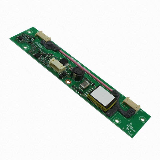
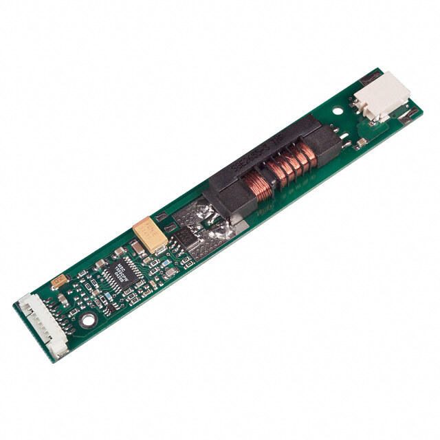
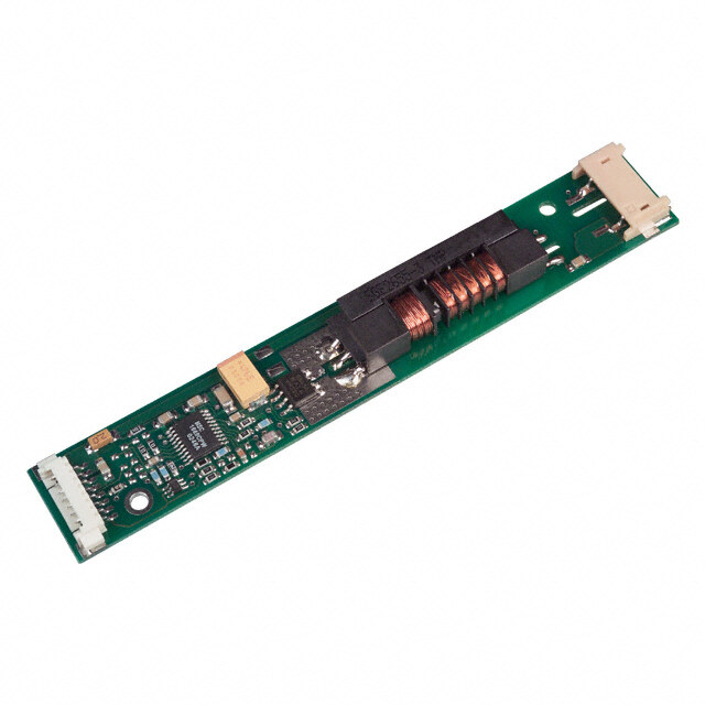
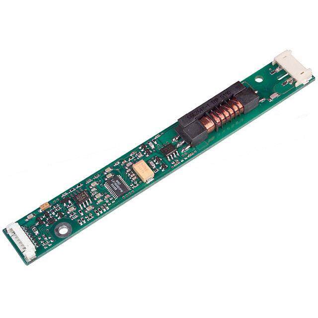
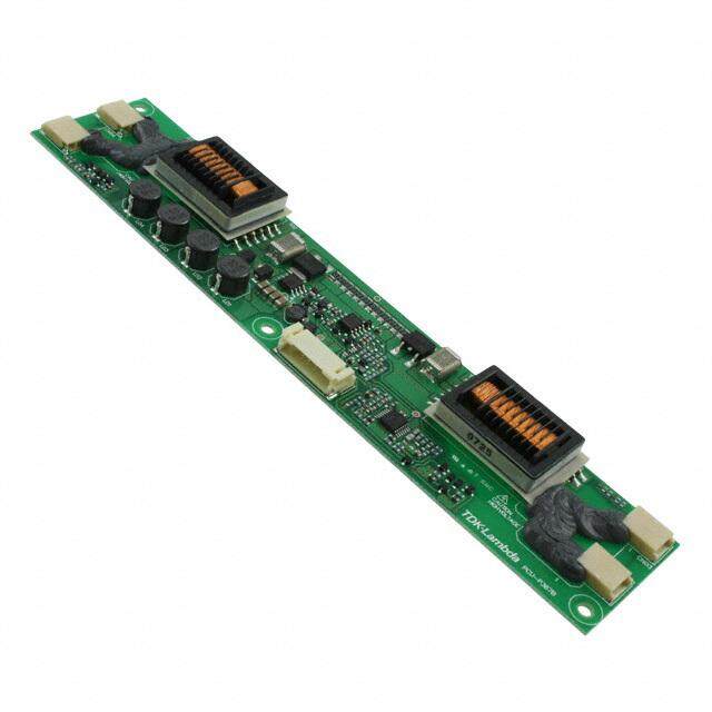
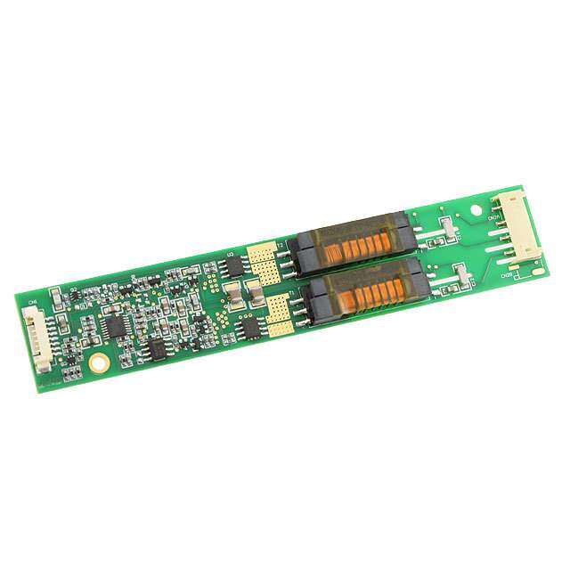
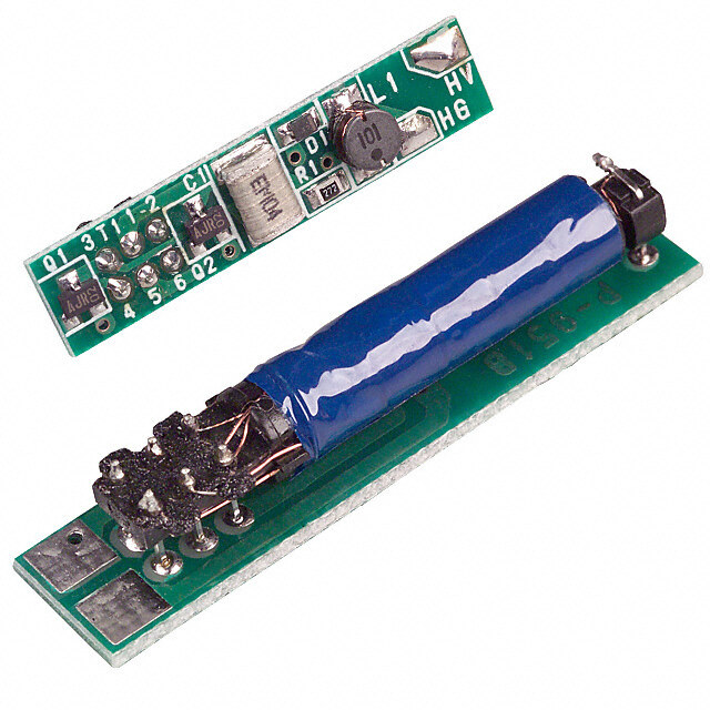
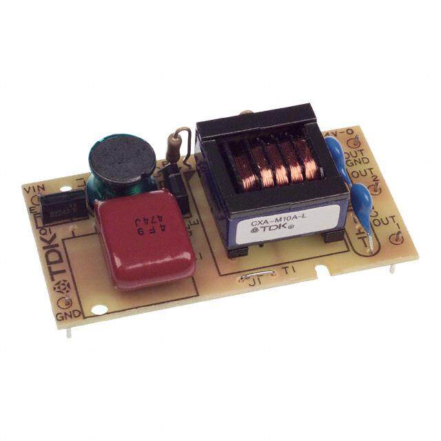
ICGOO电子元器件商城为您提供CXA-0549由TDK设计生产,在icgoo商城现货销售,并且可以通过原厂、代理商等渠道进行代购。 CXA-0549价格参考。TDKCXA-0549封装/规格:反相器, CCFL 和 UV 灯 Inverter 10.8 ~ 13.2V Input 1500V Output 5.51" 长 x 1.18" 宽 x 0.31" 高(140mm x 30mm x 8mm) 底座安装。您可以下载CXA-0549参考资料、Datasheet数据手册功能说明书,资料中有CXA-0549 详细功能的应用电路图电压和使用方法及教程。
| 参数 | 数值 |
| 产品目录 | |
| 描述 | INVERTER 12V-INPUT 1500V-OUTPUTEL/CCFL 逆变器和配件 Dimming |
| 产品分类 | |
| 品牌 | TDK |
| 产品手册 | |
| 产品图片 |
|
| rohs | 符合RoHS无铅 / 符合限制有害物质指令(RoHS)规范要求 |
| 产品系列 | EL/CCFL 逆变器和配件,TDK CXA-0549- |
| mouser_ship_limit | 该产品可能需要其他文件才能进口到中国。 |
| 数据手册 | |
| 产品型号 | CXA-0549 |
| 产品目录页面 | |
| 产品种类 | EL/CCFL 逆变器和配件 |
| 其它名称 | 445-5393 |
| 功能 | Dimming Inverter |
| 商标 | TDK |
| 大小/尺寸 | 5.51" 长 x 1.18" 宽 x 0.31" 高(140mm x 30mm x 8mm) |
| 安装类型 | 底座安装 |
| 封装 | Bulk |
| 工厂包装数量 | 40 |
| 标准包装 | 40 |
| 电压-输入 | 10.8 ~ 13.2V |
| 类型 | 用于 CCFL 和 UV 灯的逆变器 |
| 输入电压 | 10.8 V to 13.2 V |
| 输入电流 | 6 A |
| 输出 | 1500V |
| 输出电压 | 1.25 kV |
| 输出端数量 | 2 |


- 商务部:美国ITC正式对集成电路等产品启动337调查
- 曝三星4nm工艺存在良率问题 高通将骁龙8 Gen1或转产台积电
- 太阳诱电将投资9.5亿元在常州建新厂生产MLCC 预计2023年完工
- 英特尔发布欧洲新工厂建设计划 深化IDM 2.0 战略
- 台积电先进制程称霸业界 有大客户加持明年业绩稳了
- 达到5530亿美元!SIA预计今年全球半导体销售额将创下新高
- 英特尔拟将自动驾驶子公司Mobileye上市 估值或超500亿美元
- 三星加码芯片和SET,合并消费电子和移动部门,撤换高东真等 CEO
- 三星电子宣布重大人事变动 还合并消费电子和移动部门
- 海关总署:前11个月进口集成电路产品价值2.52万亿元 增长14.8%
PDF Datasheet 数据手册内容提取
MESSRS : Product Drawing CUSTOMER'S PRODUCT NAME: TDK PRODUCT NAME: DC/AC INVERTER UNIT CXA-0549 TENTATIVE *Notice Product Drawing is not contract. This is only technical data. This technical data may change internal description without any notice. When you design final product please request us specification through our sales or distributors. After you receive the specification, the contract is effective on signature of the specification. TDK-Lambda Corporation PREPARED BY APPROVED BY AUTHORIZED BY April . 20 . 2010 April . 20 . 2010 April . 20 . 2010 S.Goya K.Yamaishi H.Masuoka DWG.No. CTR-3835-A
Precautionary Notes Regarding the Use of This Inverter When using this product, give due consideration to the precautionary notes described below and ensure a safe design. Inappropriate use may result in electric shock, injury or fire. Warning (cid:121)This product is subject to high voltage. Do not touch it while the power is on. E Failing to do so may result in electric shock. Caution (cid:121)This product is designed for lighting Cold Cathode Fluorescent LampVs. Do not use it with any other load. (cid:121)Store this product under the conditions defined in the specification document. (cid:121)Do not store this product in an environment where dust, dirt or corrosive gas(salt,acid,base, etc.) is present. (cid:121)This product is subject to high voltage. If there is a possibility that the user may touch the product, provide a proper warning indication in order to draw the user'sI attention. (cid:121)This product is designed for use with general electronic equipment. If it is to be used with medical equipment that directly affecTts human life or for the control of transportation equipment to which passengers entrust their lives, provide thorough fail-safe measures. (cid:121)Consult us before using if this product is to be installed in a habitual vibration environment (vehicel, etc.). (cid:121)Avoid using this product under high temperatures or high humidity or in an environment in which dust, dirt or any corrosive gas (salt,acid,base, etc.) is present. A Also,be careful not to allow the formation of dew condensation. It may result in damage or electric shock. (cid:121)If the product does not have a built-in protective circuit (circuit breaker, fuse, etc.), it is recommended that a fuse be used at the input stage to prevent the generation of smoke or fire in the event of a malfunction. Even when the product has a built-in protective circuit (circuit breaker, fuse, etc.), T the circuit may not function properly due to inappropriate operating conditions or power-supply capacity. It is recommended that an appropriate protective circuit (circuit breaker, fuse, etc.) be provided separately from the built-in circuit. (cid:121)Use the product only within the specified input voltage, output power, output voltage and operating temperature ranges. ENxceeding these values may result in damage, etc. (cid:121)Provide a measure for the prevention of surge voltage due to lightning, etc. Abnormal voltage may result in damage, etc. (cid:121)To prevent problems from occurring as a result of a short circuit in the high voltage section, be sure to take appropriate measures to prevent the entry of foreign substances into the inverter after it is installed. (cid:121)This product is not designed to provide resistance to radiation. E (cid:121)In order to protect the inverter from vibration and shock, be sure to use all the mounting holes when installing the inverter. (cid:121)Ripples could be superimposed on the voltage and the current in the input source connected to the inverter , depending on the impedance in the input source, wiring, etc. When you select an inTput source, please check waveforms, etc on the final set. (cid:121)Please use all the mounting holes, because to defend the converter from vibration and impact. Handling Precautions (cid:121)This product uses thin wires. Observe the following precautions and handle it with care so as not to cause wire breakage. Broken wire may result in damage, etc. (cid:153)Do not stack multiple products on top of one another. (cid:153)Do not allow the product to come in contact with tools, etc. (cid:121)Do not apply excessive stress during installation. It may cause chipping and cracking,resulting in damage, etc. (cid:121)Provide clearance between the high-voltage section of this product and the frame body on which the product is installed and also the conductor section as on page 2 , [1] ”Outline” . (cid:121)Do not use the product after it has been dropped because there is the possibility that components have been damaged. No. MATERIALS NAME QU MATERIAL REMARK PRODUCT NAME or MODEL,TITLE DC-AC INVERTER UNIT CXA-0549 NAME OF DRAWING DRAWING No. PAGE TDK-Lambda Product Drawing CTR-3835-A 1 <The specifications may be changed without any notice.> TSB-08-01-05(00) form-6(A4)
1. Part Name The part name is CXA-0549. 2. Contents Item AEttched view Page 1.Appearance,Structure and Dimensions Outline Vrefer to [1] 3 Pin configration refer to [1] 4 2.Characteristics I T Absolute Maximum Ratings refer to [2] 5 3.Electrical Characteristics refer to [3] 5 A 4.Test circuit refer to [4] 6 5.Reliability Test refer to [5] 7 T 6.Packing and Marking refer to [6] 8 7.Others N Test Cond Std Warranty refer to [7] 8 Others E T No. MATERIALS NAME QU MATERIAL REMARK PRODUCT NAME or MODEL,TITLE DC-AC INVERTER UNIT CXA-0549 NAME OF DRAWING DRAWING No. PAGE TDK-Lambda Product Drawing CTR-3835-A 2 <The specifications may be changed without any notice.> TSB-08-01-05(00) form-6(A4)
●Features● ・This inverter is for two lamps. It has Dimming function(PWM System) and Remote function. ・With lamp failure detector. Normal Operation : CN1-4=0V Some Lamps Open : CN1-4=5V ・The high-voltage area (terminals and patterns) is coated with silicone so as to avoid the defects caused by dust. ・This product is conformity to RoHS directive.(※) (※)Conformity to RoHS Directive:This means that, in conformity with EU EDirective 2002/95/EC, lead, cadmium, hexavalent chromium, and specific bromine-based flame retardants, PBB and PBDE, have not been used,except for exempted applications. [1] Outline 1-1. Outline SILICONE Label (Examlpe) TDK part VNo, Date code, Country of origin , TDK-Lambda Logo. UL mark TOP VIEW 140±0.5 5 3 70±0.5 0. (0.8) 66.5±0.3 I66.5±0.3 ±8.5 CN2 CN3 T 1 5 1 1 L1 CXA-0549 0.2 ±0. (4) CN1 T MD K A - DL a E9m ZIbN1d6 JaAPAN ±18 30 A 5 3 5-φ3±0.2 52.5±0.3 52.5±0.3 0. ± LEAD WIRE (High voltage generation area) 5 ③ ① ② ③ 3. Note1 .A slanted line department in an upTper figure expresses silicone application position. SIDE VIEW 8MAX X N 1) A 40mm 55mm ( M 8 (a:High Voltage generation area) (a:High Voltage generation area) 0. Unit:mm BOTTOM VIEW TAPE Weight:22.0g.typ. E T Sectional view SILICONE(SE9168RTV) LEAD WIRE(UL3239 10kV) SOLDER PWB ※Please secure 3mm or longer space distance from the high voltage generating area in all directions. Please see Note 1-3 for the details. No. Part Description Material Qu Remark ① PCB Composite (CEM-3) 1 UL94V-0 t=1.0 ② Input Connector CN1 S5B-PH-SM4-TB(LF)(SN) 1 JST ③ Output Connector CN2, CN3 SM02(8.0)B-BHS-1-TB(LF)(SN) 2 JST No. MATERIALS NAME QU MATERIAL REMARK PRODUCT NAME or MODEL,TITLE DC-AC INVERTER UNIT CXA-0549 NAME OF DRAWING DRAWING No. PAGE TDK-Lambda Product Drawing CTR-3835-A 3 <The specifications may be changed without any notice.> TSB-08-01-05(00) form-6(A4)
1-2. Connector Configuration Input side Output side : CN2 Pin No. Symbols Ratings Notes Pin No. Symbols Ratings Notes CN1-1 Vin 10.8~13.2V Input Voltage CN2-1 VHIGH1 (460Vrms) Output 1 CN1-2 GND 0V GND CN2-3 VLEOW1 (5V) Output 1 Return CN1-3 Vbr 0~2.5V Dimming Control Vst The warning output Output side : CN3 CN1-4 0V/5V 5V in abnormal (出力) circumstances Pin No. Symbols Ratings Notes V CN1-5 Vrmt -1~Vin+1V Remote Control CN3-1 VHIGH2 (460Vrms) Output 2 CN3-3 VLOW2 (5V) Output 2 Return I Note1-1. Marking of TDK part No, Date code, Country of origin,TDK-Lambda Logo, UL mark. 1) TDK part No., Date code, Country of origin, TDK-LaTmbda Logo, UL mark is marked on the transformer. 2) Date code example. (ex. Dec. 16. 2009) 9 Z 1 6 A Two digits of production day. One digit of production month. (Oct. : X, Nov. : Y, Dec. : Z). TLast digit of production year. 3) Country of origin code example. (ex. MADE IN JAPAN. MADE IN CHINA,MADE IN MALAYSIA). N Note1-2. For circuit connection, please prefer to test circuit diagram [4]. Note1-3. Please use minimum of 3mm clearance (all directions) between inverter high voltage area and any conductors. Please refer to mechanicEal drawing for marking of high voltage area. Note1-4. Open voltage (strike voltage) is measured across the transformer secondary winding at no load as the reading at the output connector would be less than the actual value. Note1-5. If the start up voltage falls below Cold Cathode Tube strike voltage, the CCFL will not light up easily specially at T lower ambient temperature. Please review mounting instruction to avoid any abnormal operation due to coupling/leakage capacitance of inverter high voltage area to any surrounding conductor. Fig1.High Voltage Code OK NG LCD Module LCD Module CN2,CN3 CN2,CN3 No. MATERIALS NAME QU MATERIAL REMARK PRODUCT NAME or MODEL,TITLE DC-AC INVERTER UNIT CXA-0549 NAME OF DRAWING DRAWING No. PAGE TDK-Lambda Product Drawing CTR-3835-A 4 <The specifications may be changed without any notice.> TSB-08-01-05(00) form-6(A4)
Note1-6. Please check your lamp characteristic for minimum operational current and set the limit point in your design to avoid flickering and/or abnormal operation. Note1-7. For proper operation of circuit protection (fuse or IC PROTECTOR),Please use minimum of 3.5A capacity for input power supply. Note1-8. Impedence from the wire connection can cause a ripple in the input. EThe product has an internal fuse of 1.75A. Please check that input current peak wave form does not exceed 1.75A. [2] Absolute maximum ratings V Items Symbols Specification Unit Notes Vin 0~14.4 Input Voltage Vrmt VDC Vbr 0~3 I Load Resistance RL1,2 85 kΩ T Operating Temp. range Ta -20~70 ℃ Storage Temp. range Ts -30~85 ℃ A A maximum wet ball temperature is 38°C Humidity range RH 95 %RH No dew. T [3]Electrical specifications Conditions Specifications Item Symbol Unit Vin(V) Vrmt(V) Vbr(V) Ta(℃) RL1(kΩ) / RL2(kΩ) MIN. TYP. MAX. Output Current Io1/2 12±0.1 5±0N.25 0 23±5 74±0.5 / 74±0.5 5.7 6.0 6.7 mArms (Dimming max.) Io1/2 12±1.2 5±0.25 0 -20 ~ 70 74±0.5 / 74±0.5 5.0 6.0 7.0 mArms Output Current Io1/2 12±0.1 5±0.25 2.5±0.5 23±5 74±0.5 / 74±0.5 1.2 2.0 2.8 mArms (Dimming min.) Input Current 1 Iin1 12±1.2 5±0.25 0 23±5 74±0.5 / 74±0.5 --- 0.59 0.84 A DC Input Current 2 Iin2 12±E1.2 0 ~ 0.4 0 23±5 74±0.5 / 74±0.5 --- --- 1.0 mA DC Frequency F1 12±1.2 5±0.25 0 23±5 74±0.5 / 74±0.5 38 43 48 kHz Frequency F2 12±1.2 5±0.25 2.5 23±5 74±0.5 / 74±0.5 254 305 356 Hz (Duty) Output Open Vopen 12±1.2 5±0.25 0 23±5 ∞ / ∞ 1.25 1.50 --- kVrms Voltage T 12±0.1 5±0.25 0 ~ 2.5 23±5 74±0.5 / ∞ 4.5 5.0 5.5 V DC 12±0.1 5±0.25 0 ~ 2.5 23±5 ∞ / 74±0.5 4.5 5.0 5.5 V DC Warning Signal Vst 12±0.1 5±0.25 0 ~ 2.5 23±5 ∞ / ∞ 4.5 5.0 5.5 V DC 12±0.1 5±0.25 0 ~ 2.5 23±5 74±0.5 / 74±0.5 --- --- 0.5 V DC No. MATERIALS NAME QU MATERIAL REMARK PRODUCT NAME or MODEL,TITLE DC-AC INVERTER UNIT CXA-0549 NAME OF DRAWING DRAWING No. PAGE TDK-Lambda Product Drawing CTR-3835-A 5 <The specifications may be changed without any notice.> TSB-08-01-05(00) form-6(A4)
[4] Test circuit F 1000:1 Iin F1 F2 Vin A CN1-1 CN2-1 Vin10.8~ - (Vin) (VHIGH1) 13.2V V- C7 CN3-1 E CN1-2 (VHIGH2) 0~ Vrmt Vst (GND) Q6 C8 2.5V V- V- V- CN1-3 RL2 RL1 ~V 0/5V Vbr (Vbr) V~A ~A Vopen Q7 Iout2 Iout1 CN1-4 (Vst) CN3-3 b (VLOW2) a CN1-5 CN2-3 SW1 (Vrmt) I(VLOW1) T RL1~2:Load resistance(7W or more) A Note.4-1.SW1(ON/OFF) Operation is as following; T SW1 Operation of unit a Operation b Non operation N Open Non operation Note4-2.Safety Function Note4-3.Safety Function E Alarm Signal Function V Digital Multiple Meter(ADVA NTEST R6451A or Conditions (CN1-4)※1 equivalent) A DC Current Meter(ADVANTEST R6451A or Normality 0.5V max. equivalent) T F Frequency Countor(ADVANTE ST R6452A or Load (Lamp) 4.5~5.5V equivalent) one open ~V True RMS Meter(KEITHLEY 2001 or Load (Lamp) equivalent.) 4.5~5.5V Two open A~ High Frequency Current Meet r(KEITHLEY 2001 or equivalent) 1000:1 High Voltage Probe (Tektronix P3000 or equivalent) ※1.When any of the load is opened, the alarm output becomes 5V. No. MATERIALS NAME QU MATERIAL REMARK PRODUCT NAME or MODEL,TITLE DC-AC INVERTER UNIT CXA-0549 NAME OF DRAWING DRAWING No. PAGE TDK-Lambda Product Drawing CTR-3835-A 6 <The specifications may be changed without any notice.> TSB-08-01-05(00) form-6(A4)
LCD module Connected chart (reference) DC-AC inverter LCD module Vrmt terminal circuit (Reference) VLOW A CN1-1 ランプ VHIGH ランプ Vin 10kΩ VHIGH 15.6kΩ VLOW A CEN1-5 10kΩ Vrmt 10kΩ IC1-3 IC2-8 V Connect the High Frequency Current Meter to the Low-Voltage (VLOW) side. [5] Reliability test I Following test items are assured. T Items Conditions Judgement Low Temp. -30°C 500h Non operational A -30°C 500h Low Temp.operational Load cond.:TYP High Temp. 85°C 500h Non operational T 80°C 500h High Temp.operational Load cond.:TYP -30°C to 80°C Heat shock 30Nmin.Each 100 Cycles Electrical and apperrance should be in the Humidity spec. 60°C 90~95%RH 500h (Non operational) 10~57Hz Amplitude 0.75mm or 9.8m/s2 58~500Hz 9.8m/s2 Vibration E Sweep:11min 60min each axis X,Y,Z 980m/s2 11ms Shock Harf-sine pulse T 1 time each axis ±X,Y,Z No. MATERIALS NAME QU MATERIAL REMARK PRODUCT NAME or MODEL,TITLE DC-AC INVERTER UNIT CXA-0549 NAME OF DRAWING DRAWING No. PAGE TDK-Lambda Product Drawing CTR-3835-A 7 <The specifications may be changed without any notice.> TSB-08-01-05(00) form-6(A4)
[6] Packing and Marking A shipping box is packaged to avoid from water or damage. Following items are printed on the box. 6-1. TDK part No. CXA-0549 6-2. Manufacture E 6-3. QTY. Packing style as under Fig. (160 going in with a standard.) V Styrofoam Corrugated cardboard Product I Styrofoam 40pcs in one tray X 4trays =160pcs/one box T Packing box. A Mariking (210mm) TDK part No. Manufacture QTY. T(340mm) (480mm) N Tape Marking E (Bottom View) T [7] Others 7-1.Test conditions Unless otherwise specified, the temperature to be (25±15)℃ and humidity to be (65±20) %RH. 7-2. Warranty Warranty shall be for one year after delivery, and those products causing failure during the warranty period and which failures are attributed to the manufacturer's responsibility shall be replaced at no charge. 7-3.Oters When any doubt arises about this specification, it shall be discussed and decided upon between both parties. Shipment inspection result sheet are subject to change without notice. No. MATERIALS NAME QU MATERIAL REMARK PRODUCT NAME or MODEL,TITLE DC-AC INVERTER UNIT CXA-0549 NAME OF DRAWING DRAWING No. PAGE TDK-Lambda Product Drawing CTR-3835-A 8 <The specifications may be changed without any notice.> TSB-08-01-05(00) form-6(A4)