ICGOO在线商城 > 变压器,变换器,变量器 > 专用变压器 > CTX210411-R
 Datasheet下载
- 型号: CTX210411-R
- 制造商: Bussmann/Cooper
- 库位|库存: xxxx|xxxx
- 要求:
| 数量阶梯 | 香港交货 | 国内含税 |
| +xxxx | $xxxx | ¥xxxx |
查看当月历史价格
查看今年历史价格
CTX210411-R产品简介:
ICGOO电子元器件商城为您提供CTX210411-R由Bussmann/Cooper设计生产,在icgoo商城现货销售,并且可以通过原厂、代理商等渠道进行代购。 CTX210411-R价格参考。Bussmann/CooperCTX210411-R封装/规格:专用变压器, 。您可以下载CTX210411-R参考资料、Datasheet数据手册功能说明书,资料中有CTX210411-R 详细功能的应用电路图电压和使用方法及教程。
Eaton品牌的CTX210411-R专用变压器是一款工业级设备,主要用于特定应用场景下的电力转换与隔离。以下是其主要应用场景及特点的简要说明:

1. 工业自动化领域:CTX210411-R适用于工厂自动化系统中的电力供应,为PLC(可编程逻辑控制器)、传感器、执行器等设备提供稳定的电压和电流。它能够有效隔离干扰信号,确保控制系统稳定运行。

2. 医疗设备供电:在医疗行业中,该型号变压器可用于诊断设备(如X光机、超声波设备)或治疗设备(如手术器械、监护仪)的电源部分。其高精度的电压转换能力和电气隔离特性符合医疗设备对安全性和可靠性的严格要求。

3. 通信设施:CTX210411-R适合用于通信基站、数据中心等场景,为通信模块、服务器和其他电子设备提供高质量的电源支持。它可以减少电磁干扰,并保护敏感设备免受电网波动的影响。

4. 实验室仪器:在科研和检测领域,此变压器常用于精密仪器(如分析仪、测试台)的电源配置中。它能输出稳定的交流电,满足实验环境对电源纯净度的需求。

5. 家用电器与消费电子产品:部分CTX210411-R也可能被设计成适配高端家电或音频/视频设备的电源组件,以提升产品的性能表现并延长使用寿命。

6. 新能源技术:随着绿色能源的发展,这款变压器还可能应用于太阳能逆变器、风力发电机组件以及其他可再生能源相关产品中,作为辅助电源或信号处理单元的一部分。

总之,Eaton CTX210411-R专用变压器凭借其卓越的性能参数和可靠性,在众多需要精确控制和安全隔离的场合发挥重要作用。具体应用还需根据实际需求和技术规格进一步确认。
| 参数 | 数值 |
| 产品目录 | |
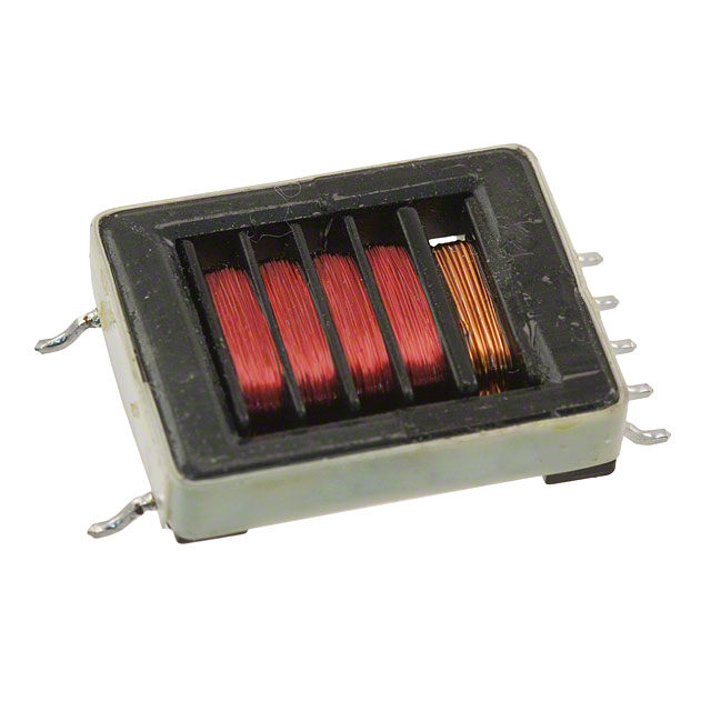
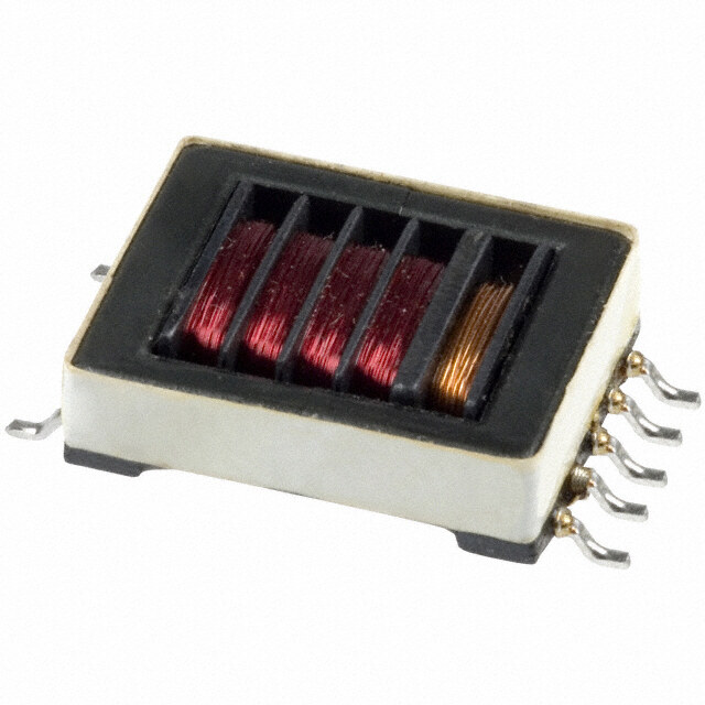
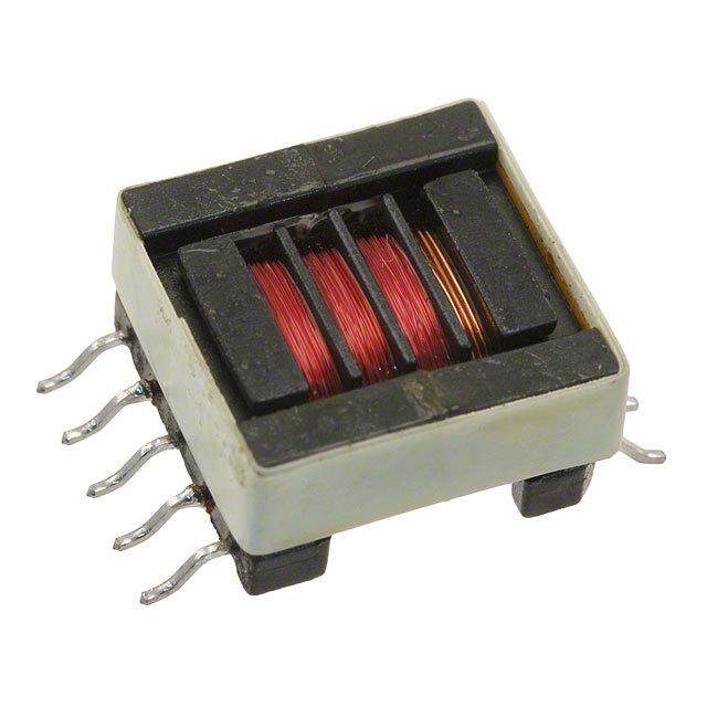
| 描述 | TRANSFORMER CCFL 4W 10V 7MA SMD电源变压器 4W 20uH 0.16ohms |
| 产品分类 | |
| 品牌 | Eaton Bussmann |
| 产品手册 | |
| 产品图片 |
|
| rohs | 符合RoHS无铅 / 符合限制有害物质指令(RoHS)规范要求 |
| 产品系列 | 电源变压器,Bussmann / Eaton CTX210411-R- |
| mouser_ship_limit | 该产品可能需要其他文件才能进口到中国。 |
| 数据手册 | |
| 产品型号 | CTX210411-R |
| 一次绕组 | Dual Primary Winding |
| 二次绕组 | Single Secondary Winding |
| 产品 | CCFL Transformers |
| 产品种类 | |
| 其它名称 | 513-1728 |
| 初级电压额定值 | 10 V |
| 功率额定值 | 4 VA |
| 单位重量 | 5.443 g |
| 商标 | Bussmann / Eaton |
| 大小/尺寸 | 21.00mm 长 x 16.50mm 宽 |
| 安装类型 | 表面贴装 |
| 安装风格 | SMD/SMT |
| 宽度 | 16.5 mm |
| 封装 | Bulk |
| 工作温度范围 | 0 C to + 70 C |
| 工厂包装数量 | 70 |
| 标准包装 | 70 |
| 次级电压额定值 | 1.34 kV |
| 电感 | 20µH |
| 端接类型 | SMD/SMT |
| 配套使用产品/相关产品 | CCFL 电源 |
| 长度 | 26 mm |
| 高度 | 5.5 mm |
| 高度-安装(最大值) | 5.50mm |


- 商务部:美国ITC正式对集成电路等产品启动337调查
- 曝三星4nm工艺存在良率问题 高通将骁龙8 Gen1或转产台积电
- 太阳诱电将投资9.5亿元在常州建新厂生产MLCC 预计2023年完工
- 英特尔发布欧洲新工厂建设计划 深化IDM 2.0 战略
- 台积电先进制程称霸业界 有大客户加持明年业绩稳了
- 达到5530亿美元!SIA预计今年全球半导体销售额将创下新高
- 英特尔拟将自动驾驶子公司Mobileye上市 估值或超500亿美元
- 三星加码芯片和SET,合并消费电子和移动部门,撤换高东真等 CEO
- 三星电子宣布重大人事变动 还合并消费电子和移动部门
- 海关总署:前11个月进口集成电路产品价值2.52万亿元 增长14.8%


PDF Datasheet 数据手册内容提取
Effective October 2015 Technical Data 4303 Supersedes March 2007 CCFL Transformers Cold cathode fluorescent lamp inverter transformers Applications • CCFL power supplies Environmental data • Storage temperature range: -40°C to +85°C • Operating ambient temperature range: 0°C to +70°C Packaging Product description • Supplied in bulk packaging • Transformers for use in CCFL power supplies, available in through-hole and surface mount Pb recess or gull wing versions, incorporating floating or fixed secondary technology • Supply output current up to 30 milli-Amps • Frequency range from 40 to 80 KHz • Deliver output power from 2.5 to 14 Watts • Operate in royer and other topologies • Ferrite core material
Technical Data 4303 CCFL Transformers Effective October 2015 Cold cathode fluorescent lamp inverter transformers Product specifications DCRp DCRs Vpri Vsec Is Schematic Pout ohms ohms TR volts volts max Vpri Vsec Mechanical PCB pad Part number diagram watts Lp uH1 max max Ns/Np max2 max2 A rms abnormal3 abnormal3 dimensions layout 2.5 Watt Versions CTX110652-R A 2.5 43 0.220 285 67 20 1340 .005 30 2000 A A CTX110655-R B 2.5 43 0.220 285 67 20 1340 .005 30 2000 A A CTX110657-R B 2.5 26 0.190 285 86 15 1340 .005 23 2000 A A CTX110659-R B 2.5 19 0.220 285 100 13 1340 .005 23 2000 A A CTX210652-R A 2.5 43 0.220 285 67 20 1340 .005 30 2000 B B CTX210655-R B 2.5 43 0.220 285 67 20 1340 .005 30 2000 B B CTX210657-R B 2.5 26 0.212 285 86 15 1340 .005 23 2000 B B CTX210659-R B 2.5 19 0.190 285 100 13 1340 .005 23 2000 B B 2.5 Watt Versions CTX210403-R C 4 44 0.220 165 50 26 1340 .007 40 2000 C C CTX210407-R C 4 27 0.160 220 86 15 1340 .007 23 2000 C C CTX210409-R C 4 20 0.160 220 100 13 1340 .007 23 2000 C C CTX210411-R C 4 20 0.160 330 125 10 1340 .007 16 2000 C C CTX310403-R C 4 44 0.220 165 50 26 1340 .007 40 2000 D D CTX310407-R C 4 27 0.160 220 86 15 1340 .007 23 2000 D D CTX310409-R C 4 20 0.160 220 100 13 1340 .007 23 2000 D D CTX310411-R C 4 20 0.160 330 125 10 1340 .007 16 2000 D D 6 Watt Versions CTX110600-R D 6 44 0.160 176 67 20 1340 .011 30 2000 E E CTX110603-R C 6 44 0.160 132 50 26 1340 .011 40 2000 E E CTX110605-R C 6 44 0.160 176 67 20 1340 .011 30 2000 E E CTX110607-R C 6 27 0.132 176 86 15 1340 .011 23 2000 E E CTX110609-R C 6 20 0.132 176 100 13 1340 .011 23 2000 E E CTX110611-R C 6 20 0.132 291 125 11 1340 .011 16 2000 E E CTX210600-R D 6 44 0.160 176 67 20 1340 .011 30 2000 F C CTX210603-R C 6 44 0.160 132 50 26 1340 .011 40 2000 F C CTX210605-R C 6 44 0.160 176 67 20 1340 .011 30 2000 F C CTX210607-R C 6 27 0.132 176 86 15 1340 .011 23 2000 F C CTX210609-R C 6 20 0.132 176 100 13 1340 .011 23 2000 F C CTX210611-R C 6 20 0.132 291 125 11 1340 .011 16 2000 F C 14 Watt Versions CTX410805-R E 14 24 0.030 262 67 20 1340 .030 30 2000 G F CTX410807-R E 14 16 0.024 272 86 15 1340 .030 23 2000 G F CTX410809-R E 14 16 0.024 314 100 13 1340 .030 23 2000 G F 1. Inductances are nominal values 2. Continuous RMS Voltage 3. Maximum Instantaneous RMS Voltage 2 www.eaton.com/elx
CCFL Transformers Technical Data 4303 Cold cathode fluorescent lamp inverter transformers Effective October 2015 Dimensions–mm 2.5 Watt Versions Mechanical A Mechanical B Pad Layout A Pad Layout B TOP VIEW TOP VIEW Schematic A Schematic B 4 Watt Versions Mechanical C Mechanical D Pad Layout C Pad Layout D TOP VIEW TOP VIEW Schematic C www.eaton.com/elx 3
Technical Data 4303 CCFL Transformers Effective October 2015 Cold cathode fluorescent lamp inverter transformers Dimensions–mm 6 Watt Versions Mechanical E Mechanical F Pad Layout E Pad Layout C TOP VIEW TOP VIEW Schematic D Schematic C 14 Watt Versions Schematic E Pad Layout F Mechanical G BOTTOM VIEW 4 www.eaton.com/elx
CCFL Transformers Technical Data 4303 Cold cathode fluorescent lamp inverter transformers Effective October 2015 Through-hole wave solder profile Reflow soldering not recommended t p Tp First Wave Second Wave e ur atTsmax erTstyp p m e TTsmin Preheat area Cool down area Time Reference EN 61760-1:2006 Profile Feature Standard SnPb Solder Lead (Pb) Free Solder Preheat • Temperature min. (Tsmin) 100°C 100°C • Temperature typ. (Tstyp) 120°C 120°C • Temperature max. (Tsmax) 130°C 130°C • Time (Tsmin to Tsmax) (ts) 70 seconds 70 seconds D preheat to max Temperature 150°C max. 150°C max. Peak temperature (TP)* 235°C – 260°C 250°C – 260°C Time at peak temperature (tp) 10 seconds max 10 seconds max 5 seconds max each wave 5 seconds max each wave Ramp-down rate ~ 2 K/s min ~ 2 K/s min ~3.5 K/s typ ~3.5 K/s typ ~5 K/s max ~5 K/s max Time 25°C to 25°C 4 minutes 4 minutes Manual solder 350°C, 4-5 seconds. (by soldering iron), generally manual, hand soldering is not recommended. www.eaton.com/elx 5
Technical Data 4303 CCFL Transformers Effective October 2015 Cold cathode fluorescent lamp inverter transformers Surface mount solder reflow profile Wave and manual soldering not recommended TP Table 1 - Standard SnPb Solder (Tc) TC -5°C Max. Ramp Up Rate = 3°C/s tP Volume Volume Package mm3 mm3 Max. Ramp Down Rate = 6°C/s Thickness <350 ≥350 TL <2.5mm) 235°C 220°C Preheat t ≥2.5mm 220°C 220°C A e Tsmax atur Table 2 - Lead (Pb) Free Solder (Tc) per Volume Volume Volume Tem Tsmin ts PThacickkangees s m<3m503 m35m03 - 2000 m>2m003 0 <1.6mm 260°C 260°C 260°C 1.6 – 2.5mm 260°C 250°C 245°C >2.5mm 250°C 245°C 245°C 25°C Time 25°C to Peak Time Reference JDEC J-STD-020D Profile Feature Standard SnPb Solder Lead (Pb) Free Solder Preheat and Soak • Temperature min. (Tsmin) 100°C 150°C • Temperature max. (Tsmax) 150°C 200°C • Time (Tsmin to Tsmax) (ts) 60-120 Seconds 60-120 Seconds Average ramp up rate Tsmax to Tp 3°C/ Second Max. 3°C/ Second Max. Liquidous temperature (Tl) 183°C 217°C Time at liquidous (tL) 60-150 Seconds 60-150 Seconds Peak package body temperature (TP)* Table 1 Table 2 Time (tp)** within 5 °C of the specified classification temperature (Tc) 20 Seconds** 30 Seconds** Average ramp-down rate (Tp to Tsmax) 6°C/ Second Max. 6°C/ Second Max. Time 25°C to Peak Temperature 6 Minutes Max. 8 Minutes Max. * Tolerance for peak profile temperature (Tp) is defined as a supplier minimum and a user maximum. ** Tolerance for time at peak profile temperature (tp) is defined as a supplier minimum and a user maximum. Life Support Policy: Eaton does not authorize the use of any of its products for use in life support devices or systems without the express written approval of an officer of the Company. Life support systems are devices which support or sustain life, and whose failure to perform, when properly used in accordance with instructions for use provided in the labeling, can be reasonably expected to result in significant injury to the user. Eaton reserves the right, without notice, to change design or construction of any products and to discontinue or limit distribution of any products. Eaton also reserves the right to change or update, without notice, any technical information contained in this bulletin. Eaton Electronics Division 1000 Eaton Boulevard Cleveland, OH 44122 United States www.eaton.com/elx © 2015 Eaton All Rights Reserved Eaton is a registered trademark. Printed in USA Publication No. PM-4303 All other trademarks are property October 2015 of their respective owners.