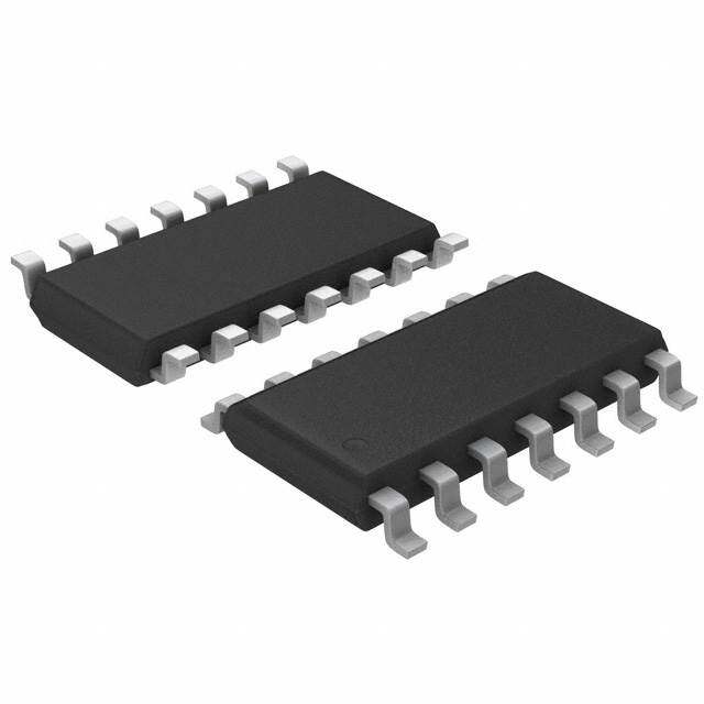
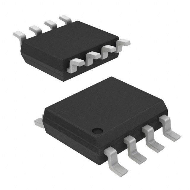
ICGOO在线商城 > 集成电路(IC) > 线性 - 放大器 - 仪表,运算放大器,缓冲器放大器 > CS3002-ISZ
- 型号: CS3002-ISZ
- 制造商: Cirrus Logic
- 库位|库存: xxxx|xxxx
- 要求:
| 数量阶梯 | 香港交货 | 国内含税 |
| +xxxx | $xxxx | ¥xxxx |
查看当月历史价格
查看今年历史价格
CS3002-ISZ产品简介:
ICGOO电子元器件商城为您提供CS3002-ISZ由Cirrus Logic设计生产,在icgoo商城现货销售,并且可以通过原厂、代理商等渠道进行代购。 CS3002-ISZ价格参考。Cirrus LogicCS3002-ISZ封装/规格:线性 - 放大器 - 仪表,运算放大器,缓冲器放大器, 通用 放大器 2 电路 满摆幅 8-SOIC。您可以下载CS3002-ISZ参考资料、Datasheet数据手册功能说明书,资料中有CS3002-ISZ 详细功能的应用电路图电压和使用方法及教程。
Cirrus Logic Inc. 的 CS3002-ISZ 是一款高性能、低功耗的仪表放大器,适用于多种精密测量和信号调理应用场景。以下是该型号的主要应用场景:

1. 医疗设备:
   - 在心电图(ECG)、脑电图(EEG)和其他生物医学传感器中,CS3002-ISZ 可以提供高精度的信号放大,确保微弱的生物电信号能够被准确采集和处理。
   - 由于其低噪声和高共模抑制比(CMRR),它非常适合用于需要高信噪比和稳定性的医疗监测设备。

2. 工业自动化:
   - 在工业控制系统中,CS3002-ISZ 可用于传感器信号的放大和调理,例如温度、压力、位移等传感器输出的微弱信号。
   - 它的高线性度和稳定性使得它在工业环境中的数据采集系统中表现出色,能够有效减少外界干扰对测量结果的影响。

3. 音频处理:
   - 在专业音频设备中,CS3002-ISZ 可用于麦克风前置放大器,提供高增益和低失真的信号放大。
   - 它的低噪声特性确保了音频信号的纯净度,适合用于高端音响设备、录音设备和广播系统。

4. 测试与测量仪器:
   - 在示波器、万用表和其他精密测量仪器中,CS3002-ISZ 可以作为前端放大器,提高测量精度和可靠性。
   - 其高输入阻抗和低失调电压特性使其特别适合用于高精度的电压测量和信号分析。

5. 消费电子:
   - 在智能家居设备、可穿戴设备和其他消费电子产品中,CS3002-ISZ 可用于传感器接口电路,提供稳定的信号放大功能。
   - 它的小尺寸和低功耗特性使其非常适合用于便携式和电池供电的设备,延长电池寿命并减小设备体积。

总之,CS3002-ISZ 凭借其卓越的性能和广泛的适用性,在多个领域中都能发挥重要作用,特别是在需要高精度、低噪声和低功耗的应用场景中表现尤为突出。
| 参数 | 数值 |
| -3db带宽 | - |
| 产品目录 | 集成电路 (IC)半导体 |
| 描述 | IC OPAMP INSTR RRO 8SOIC运算放大器 - 运放 Dual Noise-Optimized Op Amp |
| 产品分类 | Linear - Amplifiers - Instrumentation, OP Amps, Buffer Amps集成电路 - IC |
| 品牌 | Cirrus Logic |
| 产品手册 | |
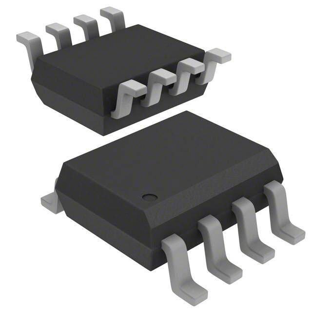
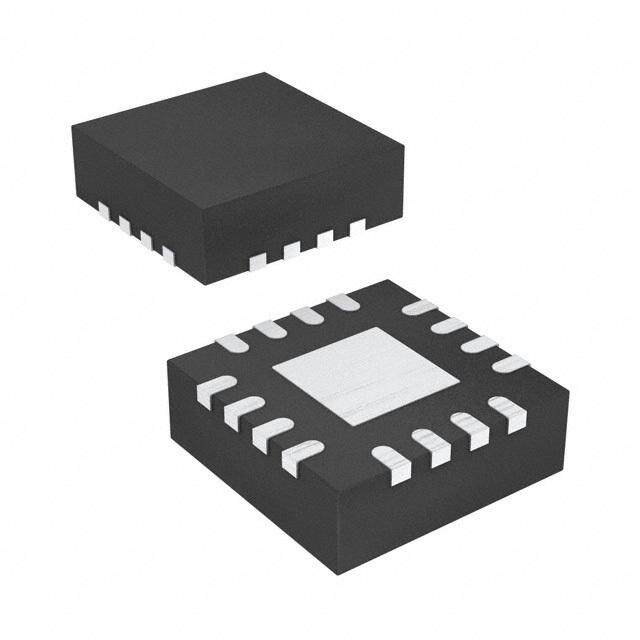
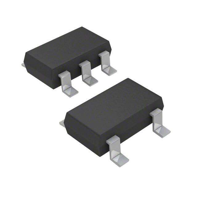
| 产品图片 |
|
| rohs | 符合RoHS无铅 / 符合限制有害物质指令(RoHS)规范要求 |
| 产品系列 | 放大器 IC,运算放大器 - 运放,Cirrus Logic CS3002-ISZ- |
| 数据手册 | |
| 产品型号 | CS3002-ISZ |
| 产品目录页面 | |
| 产品种类 | 运算放大器 - 运放 |
| 供应商器件封装 | 8-SOIC |
| 共模抑制比—最小值 | 115 dB |
| 关闭 | No Shutdown |
| 其它名称 | 598-1141-5 |
| 包装 | 管件 |
| 压摆率 | 5 V/µs |
| 双重电源电压 | +/- 3 V |
| 商标 | Cirrus Logic |
| 商标名 | CS3002 |
| 增益带宽积 | - |
| 安装类型 | 表面贴装 |
| 安装风格 | SMD/SMT |
| 封装 | Tube |
| 封装/外壳 | 8-SOIC(0.154",3.90mm 宽) |
| 封装/箱体 | SOIC-8 |
| 工作温度 | -40°C ~ 85°C |
| 工作电源电压 | 2.7 V to 6.7 V, +/- 1.35 V to +/- 3.35 V |
| 工厂包装数量 | 100 |
| 放大器类型 | Precision Amplifier |
| 最大双重电源电压 | +/- 3.35 V |
| 最大工作温度 | + 85 C |
| 最小双重电源电压 | +/- 1.35 V |
| 最小工作温度 | - 40 C |
| 标准包装 | 100 |
| 电压-电源,单/双 (±) | 2.7 V ~ 6.7 V, ±1.35 V ~ 3.35 V |
| 电压-输入失调 | 10µV |
| 电流-电源 | 3.6mA |
| 电流-输入偏置 | 100pA |
| 电流-输出/通道 | - |
| 电源电流 | 4.8 mA |
| 电路数 | 2 |
| 系列 | CS3002 |
| 转换速度 | 5 V/us |
| 输入偏压电流—最大 | 1 nA |
| 输入参考电压噪声 | 6 nV |
| 输入补偿电压 | 10 uV |
| 输出类型 | 满摆幅 |
| 通道数量 | 2 Channel |
| 配用 | /product-detail/zh/CDB30XX/598-1495-ND/2024804 |



PDF Datasheet 数据手册内容提取
CS3001 CS3002 Precision Low Voltage Amplifier; DC to 2 kHz Features Description (cid:1) Low Offset: 10 µV Max The CS3001 single amplifier and the CS3002 dual am- (cid:1) Low Drift: 0.05 µV/°C Max plifier are designed for precision amplification of low (cid:1) level signals and are ideally suited to applications that Low Noise require very high closed loop gains. These amplifiers – 6 nV/√Hz@ 0.5 Hz achieve excellent offset stability, super high open loop – 0.1 to 10 Hz= 125 nVp-p gain,andlownoiseovertimeandtemperature.Thede- vices also exhibit excellent CMRR and PSRR. The – 1/fcorner @ 0.08 Hz (cid:1) commonmodeinputrangeincludesthenegativesupply Open-Loop Voltage Gain rail.Theamplifiersoperatewithanytotalsupplyvoltage – 1000 Trillion Typ from2.7Vto6.7V(±1.35V to±3.35V). – 10 Billion Min Pin Configurations (cid:1) Rail-to-Rail Output Swing (cid:1) 1.8 mA Supply Current (cid:1) CS3001 CS3002 Slew rate: 5 V/µs Applications PWDN 1 8 NC Out A 1 8 V+ (cid:1) -In 2 - 7 V+ -In A 2 -A+ 7 Out B Thermocouple/Thermopile Amplifiers (cid:1) +In 3 + 6 Output +In A 3 +B- 6 -In B Load Cell and Bridge Transducer Amplifiers (cid:1) V- 4 5 NC V- 4 5 +In B Precision Instrumentation (cid:1) 8-leadSOIC 8-leadSOIC Battery-Powered Systems Noise vs. Frequency (Measured) CS3001 DexterResearch 100 Thermopile1M R2 64.9k z √H 10 /V n R1 C1 100 0.015µµµµF 1 0.001 0.01 0.1 1 10 Frequency (Hz) Thermopile Amplifier with a Gain of 650 V/V Thisdocumentcontainsinformationforanewproduct. Preliminary Product Information CirrusLogicreservestherighttomodifythisproductwithoutnotice. CirrusLogic,Inc. http://www.cirrus.com Copyright CirrusLogic,Inc.2002 OCT‘02 (AllRightsReserved) DS490PP1 1
CS3001 CS3002 TABLE OF CONTENTS 1. CHARACTERISTICSAND SPECIFICATIONS ...................................................3 1.1 ElectricalCharacteristics ......................................................................................3 1.2 AbsoluteMaximumRatings .................................................................................4 2. PERFORMANCE PLOTS .........................................................................................4 3. CS3001/CS3002OVERVIEW ...................................................................................7 3.1 OpenLoopGain andPhaseResponse ..................................................................7 3.2 OpenLoopGain andStabilityCompensation ......................................................8 3.3 Powerdown (PDWN) .........................................................................................10 3.4 Applications ........................................................................................................11 4. PACKAGE DRAWING ...........................................................................................13 5. ORDERING INFORMATION ...............................................................................14 LIST OF FIGURES Figure1.NoisevsFrequency(Measured).........................................................................4 Figure2.0.01Hzto10HzNoise .......................................................................................4 Figure3.NoisevsFrequency ............................................................................................4 Figure4.OffsetVoltageStability(DCto3.2Hz) ...............................................................4 Figure5.OpenLoopGainandPhasevsFrequency.........................................................5 Figure6.OpenLoopGainandPhasevsFrequency(Expanded) .....................................5 Figure7.InputBiasCurrentvsSupplyVoltage(CS3002).................................................6 Figure8.InputBiasCurrentvsCommonModeVoltage ...................................................6 Figure9.CS3001/CS3002OpenLoopGainandPhaseResponse ..................................7 Figure10.Non-InvertingGainConfiguration .....................................................................8 Figure11.Non-InvertingGainConfigurationwithCompensation......................................9 Figure12.LoopGainPlot:UnityGainandwithPole-ZeroCompensation ......................10 Figure13.ThermopileAmplifierwithaGainof650V/V ..................................................11 Figure14.LoadCellBridgeAmplifierandA/DConverter ...............................................12 ContactingCirrusLogicSupport ForallproductquestionsandinquiriescontactaCirrusLogicSalesRepresentative. Tofindonenearest yougoto<http://www.cirrus.com/corporate/contacts/sales.cfm> IMPORTANTNOTICE "Preliminary"productinformationdescribesproductsthatareinproduction,butforwhichfullcharacterizationdataisnotyetavailable. "Advance"productinfor- mationdescribesproductsthatareindevelopmentandsubjecttodevelopmentchanges.CirrusLogic,Inc.anditssubsidiaries("Cirrus")believethattheinfor- mationcontainedinthisdocumentisaccurateandreliable.However,theinformationissubjecttochangewithoutnoticeandisprovided"ASIS"withoutwarranty ofanykind(expressorimplied).Customersareadvisedtoobtainthelatestversionofrelevantinformationtoverify,beforeplacingorders,thatinformationbeing reliedoniscurrentandcomplete.Allproductsaresoldsubjecttothetermsandconditionsofsalesuppliedatthetimeoforderacknowledgment,includingthose pertainingtowarranty,patentinfringement,andlimitationofliability.NoresponsibilityisassumedbyCirrusfortheuseofthisinformation,includinguseofthis informationasthebasisformanufactureorsaleofanyitems,orforinfringementofpatentsorotherrightsofthirdparties.ThisdocumentisthepropertyofCirrus andbyfurnishingthisinformation,Cirrusgrantsnolicense,expressorimpliedunderanypatents,maskworkrights,copyrights,trademarks,tradesecretsor otherintellectualpropertyrights.Cirrusownsthecopyrightsoftheinformationcontainedhereinandgivesconsentforcopiestobemadeoftheinformationonly forusewithinyourorganizationwithrespecttoCirrusintegratedcircuitsorotherpartsofCirrus.Thisconsentdoesnotextendtoothercopyingsuchascopying forgeneraldistribution,advertisingorpromotionalpurposes,orforcreatinganyworkforresale. AnexportpermitneedstobeobtainedfromthecompetentauthoritiesoftheJapaneseGovernmentifanyoftheproductsortechnologiesdescribedinthisma- terialandcontrolledunderthe"ForeignExchangeandForeignTradeLaw"istobeexportedortakenoutofJapan.Anexportlicenseand/orquotaneedstobe obtainedfromthecompetentauthoritiesoftheChineseGovernmentifanyoftheproductsortechnologiesdescribedinthismaterialissubjecttothePRCForeign TradeLawandistobeexportedortakenoutofthePRC. CERTAINAPPLICATIONSUSINGSEMICONDUCTORPRODUCTSMAYINVOLVEPOTENTIALRISKSOFDEATH,PERSONALINJURY,ORSEVERE PROPERTYORENVIRONMENTALDAMAGE("CRITICALAPPLICATIONS").CIRRUSPRODUCTSARENOTDESIGNED,AUTHORIZED,ORWARRANT- EDTOBESUITABLEFORUSEINLIFE-SUPPORTDEVICESORSYSTEMSOROTHERCRITICALAPPLICATIONS.INCLUSIONOFCIRRUSPRODUCTS INSUCHAPPLICATIONSISUNDERSTOODTOBEFULLYATTHECUSTOMER'SRISK. CirrusLogic,Cirrus,andtheCirrusLogiclogodesignsaretrademarksofCirrusLogic,Inc.Allotherbrandandproductnamesinthisdocumentmaybetrade- marksorservicemarksoftheirrespectiveowners. 2
CS3001 CS3002 1. CHARACTERISTICS AND SPECIFICATIONS 1.1 Electrical Characteristics V+=+5V,V-=0V,VCM=2.5V(Note1) CS3001/CS3002 Parameter Min Typ Max Unit InputOffsetVoltage (Note2) (cid:127) - - ±10 µV AverageInputOffsetDrift (Note2) (cid:127) - ±0.01 ±0.05 µV/ºC LongTermInput Offset VoltageStability (Note3) InputBiasCurrent T =25ºC - ±100 ±200 pA A (cid:127) ±1000 pA InputOffsetCurrent T =25ºC - ±200 ±400 pA A (cid:127) ±2000 pA InputNoiseVoltageDensityR =100Ω,f =1Hz - 6 nV/ Hz S 0 R =100Ω,f =1kHz - 6 nV/ Hz S 0 InputNoiseVoltage 0.1to10Hz - 125 nV p-p InputNoiseCurrentDensityf =1Hz - 2 pA/ Hz 0 InputNoiseCurrent 0.1to10Hz - 40 pA p-p InputCommonModeVoltageRange (cid:127) -0.1 - (V+)-1.25 V CommonModeRejectionRatio(dc) (Note4) (cid:127) 115 120 - dB PowerSupplyRejectionRatio (cid:127) 120 136 - dB LargeSignalVoltageGain R =2kΩ toV+/2 (Note5) (cid:127) 200 300 - dB L OutputVoltageSwing R =2kΩ toV+/2 (cid:127) +4.7 - - V L R =100kΩtoV+/2 +4.99 V L SlewRate R =2k, 100pF 5 - V/µs L OverloadRecoveryTime - 100 - µs SupplyCurrentperAmplifier (cid:127) - 1.8 2.4 mA PWDN active(CS3001Only) (Note6) (cid:127) 15 µA PWDN Threshold (Note6) (cid:127) (V+)-1.0 - - V Start-upTime (Note7) (cid:127) - 9 12 ms Notes: 1. Symbol“(cid:127)”denotesspecificationappliesover-40to+85° C. 2. Thisparameterisguaranteedbydesignandlaboratorycharacterization.Thermocoupleeffectsprohibit accuratemeasurementof theseparametersinautomatictestsystems. 3. 1000-hourlifetestdata@125°Cindicatesrandomlydistributedvariationapproximatelyequalto measurementrepeatabilityof1µV. 4. Measuredwithinthespecifiedcommonmoderangelimits. 5. Guaranteedwithintheoutputlimitsof(V+-0.3V)to(V-+0.3V).Testedwithproprietaryproductiontest method. 6. PWDNinputhasaninternalpullupresistortoV+ofapproximately800kΩandisthemajorsourceof currentconsumptionwhenPWDNisactivelow. 7. Thedevicehasacontrolledstart-upbehaviorduetoitscomplexopenloopgaincharacteristics.Start- uptimeapplieswhensupplyvoltageisappliedorwhenPDWNisreleased. 3
CS3001 CS3002 1.2 Absolute Maximum Ratings Parameter Min Typ Max Unit SupplyVoltage [(V+)-(V-)] 6.8 V InputVoltage V--0.3 V++0.3 V StorageTemperatureRange -65 +150 ºC 2. PERFORMANCE PLOTS 1000 Noise vs. Frequency (Measured) 100 100 z H √ /V √Hz 10 n 10 /V n 1 1 10 100 1K 10K 100K 1M 10M 0.001 0.01 0.1 1 10 Frequency (Hz) Frequency (Hz) Figure1. NoisevsFrequency(Measured) Figure3. NoisevsFrequency 100 100 75 σ= 13 nV 50 50 25 nV 0 nV-250 -50 -50 -75 -100 0 1 2 3 4 5 6 7 8 9 10 -100 TIME (Sec) Time (1 Hour) Figure2. 0.01Hzto10HzNoise Figure4. OffsetVoltageStability(DCto3.2Hz) 4
CS3001 CS3002 Performance Plots (Cont.) 500 400 300 ) s Gain e 200 ) e B gr 100 d e ( D 0 n ai e ( -100 G s a -200 h P Phase -300 -400 -500 1 10 100 1K 10K 100K 1M 10M Frequency (Hz) Figure5. OpenLoopGainandPhasevsFrequency 100 80 60 ) B d ( n 40 ai G 20 0 -45 -90 ) s e -135 e r g e -180 D ( e -225 s a h -270 P -315 -360 10K 100K 1M 10M Figure6. OpenLoopGainandPhasevsFrequency(Expanded) 5
CS3001 CS3002 Performance Plots (Cont.) -150 )A -100 A1- p A1+ ( tn -50 BA12-+ e r B1+ ru 0 A2- C sa -50 iB tu -100 B2- p nI -150 CM = 0 V B2+ -200 ±1.35 ±2 ±2.5 ±3.35 Supply Voltage (±V) Figure7. InputBiasCurrentvsSupplyVoltage(CS3002) V 5 . 2 = 3 ntM 2 eC rro 1 u 0 t C d -1 s e az -2 Biali -3 m r 0 1 2 3 4 5 o N Common Mode Voltage (Vs = 5V) Figure8. InputBiasCurrentvsCommonModeVoltage 6
CS3001 CS3002 3. CS3001/CS3002 OVERVIEW foramplifyingsmallsignalswithlargegainsinap- plications where the output of the amplifier can be The CS3001/CS3002 amplifiers are designed for band-limited tofrequencies below 2kHz. precision measurement of signals from DC to 2kHz when operating from a supply voltage of 3.1 Open Loop Gain and Phase +2.7 V to +6.7V (± 1.35to ± 3.35V).Theampli- Response fiers are designed with a patented architecture that Figure 9illustratestheopenloopgainandphasere- utilizesmultipleamplifierstages toyieldveryhigh sponse of the CS3001/CS3002. The gain slope of openloopgainatfrequenciesof10kHzandbelow. the amplifier is about –100 dB/decade between The amplifiers yield low noise and low offset drift 500Hz and 60 kHz and transitions to –20 dB/de- whileconsumingrelativelylowsupplycurrent.An cade between 60 kHz and its unity gain crossover increase in noise floor above 2 kHz is the result of frequencyatabout4.8MHz.Phasemarginatunity intermediate stages oftheamplifierbeingoperated gain is about 70 degrees; gain margin is about at very low currents. The amplifiers are intended 20dB. 100 80 -100 dB/ dec 60 ) B d ( n 40 ai -20 dB/ dec G 20 0 -45 -90 ) s e -135 e r g e -180 D ( e -225 s a h -270 P -315 -360 10K 100K 1M 10M Figure9. CS3001/CS3002OpenLoopGainandPhaseResponse 7
CS3001 CS3002 3.2 Open Loop Gain and Stability 50pF. This capacitance adds an additional pole in Compensation the loop gain transfer function at a frequency of The CS3001 and CS3002 achieve ultra-high open f= 1/(2πR*C ) where R is the parallel combina- in loop gain. Figure10 illustrates the amplifier in a tionofR1andR2 (R1 || R2).AhighervalueforR non-inverting gain configuration. The open loop producesapoleatalowerfrequency,thusreducing gain and phase plots indicate that the amplifier is the phase margin. R1 is recommended to be less stableforclosed-loopgainslessthan50V/V.Fora than or equal to 100 ohms, which results in a pole gainof50,thephasemarginisbetween40°and60° at 30MHz or higher. If a higher value ofR1 is de- depending upon the loading conditions. As shown sired, a compensation capacitor (C2) should be inFigure 11onpage9,theopamphasaninputca- added in parallel with R2. C2 should be chosen pacitance at the + and – signal inputs of typically such thatR2*C2 ≥ R1*C . in R S Vin Vo R2 R1 Figure10. Non-InvertingGainConfiguration 8
CS3001 CS3002 Vin C in 50 pF Vo 50 pF C in R2 ≥ R1 Choose C2 so that R2C2 R1C in C2 Figure11. Non-InvertingGainConfigurationwithCompensation The feedback capacitor C2 is required for closed- This indicates that the separation of the pole and loop gains greater than 50 V/V. The capacitor in- the zero is governed by the closed loop gain. It is troduces a pole and a zero in the loop gain transfer required that the zero falls on the steep slope function, (–100 dB/decade)oftheloopgainplotsothatthere is some gain higher than 0 dB (typically 20 dB) at the hand-over frequency (the frequency at which s – 1+----- the slope changes from – 100 dB/decade to z T = -------------------1----A –20dB/decade). s ol 1+----- p 1 1 1 P = -------------------------------------≅------------------------- for R »R 1 2π(R ||R )C 2π(R C ) 2 1 1 2 2 1 2 Z = -----------------1------------------ where A = R-----2- 1 2π(A×R )C R 1 2 1 9
CS3001 CS3002 The loop gain plot shown in Figure12 illustrates Capacitor C2 can be increased in value to limit the theunitygainconfiguration,andindicateshowthis amplifier’s rising noise above 2kHz. is modified when using the amplifier in a higher 3.3 Powerdown (PDWN) gain configuration with compensation. If it is con- The CS3001 single amplifier provides a power- figured for higher gain, for example, 60 dB, the down function on pin 1. If this pin is left open the x–axis will move up by 60 dB (line B). Capacitor amplifier will operate normally. If the powerdown C2 adds a zero and a pole. The modified plot indi- is asserted low, the amplifier will go into a low cates the effects of introducing the pole and zero power state. There is a pull-up resistor (approxi- duetocapacitorC2.Thepolecanbelocatedatany mately 800 k ohm) inside the amplifier from pin frequencyhigherthanthehand-overfrequency,the 1totheV+supply.Thecurrentthroughthispull-up zero has to be at a frequency lower than the hand- resistor is the main source of current drain in the overfrequencysoastoprovideadequategainmar- powerdownstate. gin. The separation between the pole and the zero is governed by the closed loop gain. The zero (z ) 3.4 Applications 1 occurs at the intersection of the –100 dB/decade The CS3001 and CS3002 amplifiers are optimum and –80 dB/decade slopes. The point X in the fig- forapplicationsthatrequirehighgainandlowdrift. ure should be at closed loop gain plus 20 dB gain Figure 13 illustrates a thermopile amplifier with a margin. The value for C2 = 1/(2πR1p1). Using gainof650V/V.Thethermopileoutputsonlyafew p1=1MHzworksverywellandisindependentof millivoltswhensubjectedtoinfraredradiation.The gain. As the closed loop gain is changed, the zero amplifieriscompensatedandbandlimitedbyC1in location is also modified if R1 remains fixed. combinationwith R2. -100 dB/dec ) n ai g g o z1 L T| ( p1 | -80 dB/dec X Margin B Desired Closed -20 dB/dec Loop Gain 50kHz 1MHz 5MHz FREQUENCY Figure12. LoopGainPlot:UnityGainandwithPole-ZeroCompensation 10
CS3001 CS3002 Figure 14 on page12 illustrates a load cell bridge fully differential ± 3.8 V into the CS5510/12 A/D amplifier with a gain of 768 V/V. The load cell is converter.This circuitoperates from +5V. excitedwith+5Vandhasa1mV/Vsensitivity.Its A similar circuit operating from +3 V can be full scale output signal is amplified to produce a constructed using the CS5540/CS5541 A/D con- verters. CS3001 DexterResearch Thermopile 1M R2 64.9k R1 C1 100 0.015µµµµF Thermopile Amplifier with a Gain of 650 V/V Figure13. ThermopileAmplifierwithaGainof650V/V 11
CS3001 CS3002 +5V +5V +5V VA 0.1µF V+ VREF CS + x768 100Ω µµµµ SDO AIN+ SCLK - 140kΩ 0.22µF CS5510/12 1mV/V 350Ω + - 365Ω 0.047µF 140kΩ 0.22µF Counter/Timer - AIN1 V- + 100Ω SCLK=10kHzto100 kH (32.768 SCLK = 10 ikHl)z to 100 kHz (32.768 nominal) Figure14. LoadCellBridgeAmplifierandA/DConverter 12
CS3001 CS3002 4. PACKAGE DRAWING 8L SOIC (150 MIL BODY) PACKAGE DRAWING E H 1 b D c SEATING ∝ PLANE A L e A1 INCHES MILLIMETERS DIM MIN MAX MIN MAX A 0.053 0.069 1.35 1.75 A1 0.004 0.010 0.10 0.25 B 0.013 0.020 0.33 0.51 C 0.007 0.010 0.19 0.25 D 0.189 0.197 4.80 5.00 E 0.150 0.157 3.80 4.00 e 0.040 0.060 1.02 1.52 H 0.228 0.244 5.80 6.20 L 0.016 0.050 0.40 1.27 ∝ 0° 8° 0° 8° JEDEC#:MS-012 13
CS3001 CS3002 5. ORDERING INFORMATION Part# TemperatureRange PackageDescription CS3001-IS -40°Cto+85°C 8-leadSOIC CS3002-IS -40°Cto+85°C 8-leadSOIC Note:AddtheletterRtothePart#toorderreels.Thereare2000piecesperreel. 14
• Notes (cid:127)
None
This datasheet has been downloaded from: www.DatasheetCatalog.com Datasheets for electronic components.
Mouser Electronics Authorized Distributor Click to View Pricing, Inventory, Delivery & Lifecycle Information: C irrus Logic: CS3001-IS CS3001-ISZ CS3001-ISZR CS3002-IS CS3002-ISZ CS3002-ISZR
 Datasheet下载


