ICGOO在线商城 > 电阻器 > 芯片电阻 - 表面安装 > CRHV2512AF12M0FKE5

 Datasheet下载
- 型号: CRHV2512AF12M0FKE5
- 制造商: Vishay
- 库位|库存: xxxx|xxxx
- 要求:
| 数量阶梯 | 香港交货 | 国内含税 |
| +xxxx | $xxxx | ¥xxxx |
查看当月历史价格
查看今年历史价格
CRHV2512AF12M0FKE5产品简介:
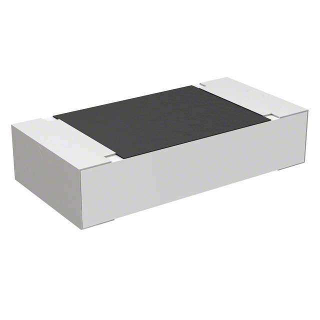
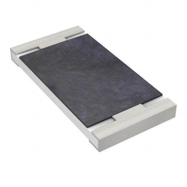
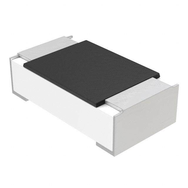
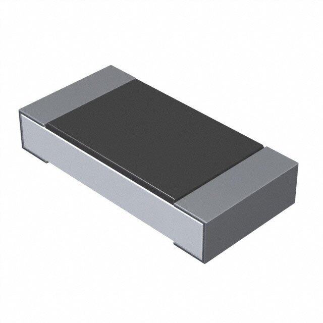
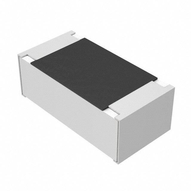
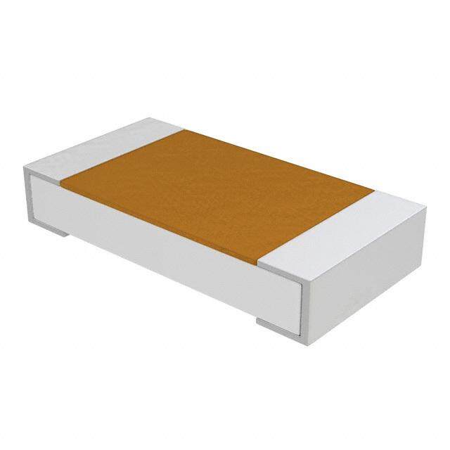
ICGOO电子元器件商城为您提供CRHV2512AF12M0FKE5由Vishay设计生产,在icgoo商城现货销售,并且可以通过原厂、代理商等渠道进行代购。 CRHV2512AF12M0FKE5价格参考¥14.32-¥18.15。VishayCRHV2512AF12M0FKE5封装/规格:芯片电阻 - 表面安装, 12 MOhms ±1% 1W 厚膜 芯片电阻 2512(6432 公制) 高电压 厚膜。您可以下载CRHV2512AF12M0FKE5参考资料、Datasheet数据手册功能说明书,资料中有CRHV2512AF12M0FKE5 详细功能的应用电路图电压和使用方法及教程。
| 参数 | 数值 |
| 产品目录 | |
| 描述 | RES 12.0M OHM 1% .7W 2512 HV |
| 产品分类 | |
| 品牌 | Vishay Dale |
| 数据手册 | |
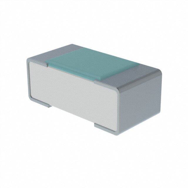
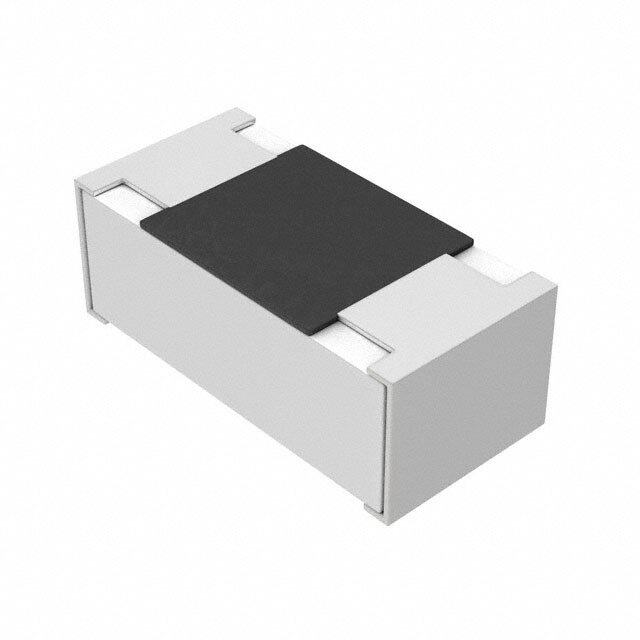
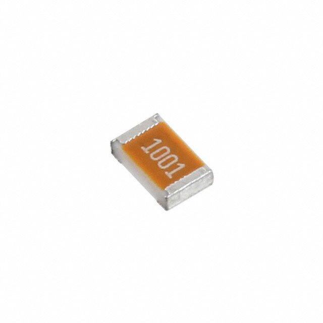
| 产品图片 |
|
| 产品型号 | CRHV2512AF12M0FKE5 |
| rohs | 无铅 / 符合限制有害物质指令(RoHS)规范要求 |
| 产品系列 | CRHV |
| 供应商器件封装 | 2512 |
| 其它名称 | CRHV12.0MECT |
| 功率(W) | 0.7W |
| 包装 | 剪切带 (CT) |
| 大小/尺寸 | 0.250" 长x 0.126" 宽(6.35mm x 3.20mm) |
| 容差 | ±1% |
| 封装/外壳 | 2512(6432 公制) |
| 成分 | 厚膜 |
| 标准包装 | 1 |
| 温度系数 | ±100ppm/°C |
| 特性 | - |
| 电阻(Ω) | 12M |
| 端子数 | 2 |
| 高度 | 0.027"(0.69mm) |


- 商务部:美国ITC正式对集成电路等产品启动337调查
- 曝三星4nm工艺存在良率问题 高通将骁龙8 Gen1或转产台积电
- 太阳诱电将投资9.5亿元在常州建新厂生产MLCC 预计2023年完工
- 英特尔发布欧洲新工厂建设计划 深化IDM 2.0 战略
- 台积电先进制程称霸业界 有大客户加持明年业绩稳了
- 达到5530亿美元!SIA预计今年全球半导体销售额将创下新高
- 英特尔拟将自动驾驶子公司Mobileye上市 估值或超500亿美元
- 三星加码芯片和SET,合并消费电子和移动部门,撤换高东真等 CEO
- 三星电子宣布重大人事变动 还合并消费电子和移动部门
- 海关总署:前11个月进口集成电路产品价值2.52万亿元 增长14.8%
PDF Datasheet 数据手册内容提取
CRHV www.vishay.com Vishay Techno Thick Film Chip Resistors, High Voltage FEATURES • High voltage up to 3000 V • Outstanding stability < 0.5 % Available • Flow solderable • Custom sizes available Available • Automatic placement capability • Tape and reel packaging available • Termination style: 3-sided wraparound termination or single termination flip chip standard; 5-sided wraparound termination available • Internationally standardized sizes • Suitable for solderable, epoxy bondable, or wire bondable applications • Termination material: solder-coated nickel barrier or solder coated non-magnetic terminations standard; gold, palladium silver, platinum gold, platinum silver or platinum palladium gold terminations available • Multiple styles, termination materials and configurations, allow wide design flexibility • Epoxy bondable or wire bondable non-magnetic terminations available • Material categorization: for definitions of compliance please see www.vishay.com/doc?99912 Note * This datasheet provides information about parts that are RoHS-compliant and / or parts that are non RoHS-compliant. For example, parts with lead (Pb) terminations are not RoHS-compliant. Please see the information / tables in this datasheet for details STANDARD ELECTRICAL SPECIFICATIONS MAXIMUM TEMPERATURE POWER RATING RESISTANCE GLOBAL WORKING TOLERANCE (3) COEFFICIENT (4) CASE SIZE P RANGE (2) MODEL 70 °C VOLTAGE (1) ± % (-55 °C to +155 °C) W V ± ppm/°C 2M to 100M 0.5 CRHV1206 1206 0.30 1500 2M to 1G 1, 2, 5, 10, 20 100 1.1G to 8G 2, 5, 10, 20 4M to 100M 0.5 CRHV1210 1210 0.45 1750 4M to 1G 1, 2, 5, 10, 20 100 1.1G to 10G 2, 5, 10, 20 6M to 100M 0.5 6M to 1G 1, 2, 5, 10, 20 CRHV2010 2010 0.50 2000 100 1.1G to 10G 2, 5, 10, 20 11G to 35G 5, 10, 20 10M to 100M 0.5 10M to 1G 1, 2, 5, 10, 20 CRHV2510 2510 0.60 2500 100 1.1G to 10G 2, 5, 10, 20 11G to 40G 5, 10, 20 12M to 100M 0.5 12M to 1G 1, 2, 5, 10, 20 CRHV2512 2512 1.0 3000 100 1.1G to 10G 2, 5, 10, 20 11G to 50G 5, 10, 20 Notes • For non-standard sizes, lower values or higher power rating requirement, contact factory (1) Continuous working voltage shall be P x R or maximum working voltage, whichever is less (2) Resistance values below 1 G are calibrated at 100 VDC, and values of 1 G and above are calibrated at 1000 VDC. Calibration at other voltages available upon request (3) Contact factory for tighter tolerances (4) Reference only: not for all values specified. Consult factory for your size and value. The TC for “AA” option is typically 200 ppm Revision: 18-Apr-17 1 Document Number: 68002 For technical questions, contact: te1resistors@vishay.com THIS DOCUMENT IS SUBJECT TO CHANGE WITHOUT NOTICE. THE PRODUCTS DESCRIBED HEREIN AND THIS DOCUMENT ARE SUBJECT TO SPECIFIC DISCLAIMERS, SET FORTH AT www.vishay.com/doc?91000
CRHV www.vishay.com Vishay Techno GLOBAL PART NUMBER INFORMATION New Global Part Numbering: CRHV1206AF100MFKFB (preferred part number format) C R H V 1 2 0 6 A F 1 0 0 M F K F B GLOBAL TERMINAL TERMINAL RESISTANCE SOLDER SIZE TOLERANCE TCR PACKAGING MODEL STYLE MATERIAL VALUE TERMINATION CRHV 1206 A = 3-sided F = nickel barrier M = M D = ± 0.5 % K = 100 ppm E = Sn100 B = bulk 1210 B = top only G = non-magnetic G = G F = ± 1 % L = 150 ppm F = Sn95/Ag5, HSD F = T/R 2010 C = 5-sided A = palladium 4M70 = 4.7 M G = ± 2 % N = 200 ppm N = No solder (full reel) 2510 silver 10M0 = 10 M J = ± 5 % R = 250 ppm S = Sn62/Pb36/Ag2, 1 = T/R 2512 B = platinum gold 1G00 = 1 G K = ± 10 % M = 300 ppm HSD (1000 pcs) C = gold M = ± 20 % W = 350 ppm T = Sn90/Pb10 5 = T/R D = platinum silver P = 500 ppm (500 pcs) E = platinum T = T/R palladium gold (250 pcs min.) W = waffle tray Historical Part Numbering: CRHV1206AF1006F100e2 (will continue to be accepted) CRHV 1206 A F 1006 F 100 e2 HISTORICAL TERM TERM RESISTANCE SOLDER SIZE TOLERANCE TCR MODEL STYLE MATERIAL VALUE TERMINATION Note • For additional information on packaging, refer to the Surface Mount Resistor Packaging document (www.vishay.com/doc?31543) MECHANICAL SPECIFICATIONS DERATING CURVE Resistive element Ruthenium oxide % 120 Encapsulation Glass n Substrate 96 % alumina wer i 100 o Scooldaetre-dc onaotne-dm naicgkneelt ibca treriremr ionra tsioonldse r ed P 80 Termination standard. Gold, palladium silver, platinum Rat 60 gold, platinum silver, platinum palladium gold terminations available. 40 Pure tin or tin/lead solder alloys standard. Solder finish Tin/silver or tin/lead/silver solder 20 alloys available. 0 - 55 - 25 0 25 50 75 100 125 155175 70 ENVIRONMENTAL SPECIFICATIONS Ambient Temperature in °C Operating Note -55 °C to +155 °C temperature • Reference only: Not for all values specified. Consult factory for Less than 0.5 % change when tested your size and value Life at full rated power Short time overload Less than 0.5 % R VOLTAGE COEFFICIENT OF RESISTANCE CHART SIZE VALUE () VCR (ppm/V) FURTHER INSTRUCTIONS CRHV1206 2M to 199M 25 Values over 200M, consult factory CRHV1210 4M to 200M 25 Values over 200M, consult factory 6M to 99M 15 CRHV2010 Values over 1G, consult factory 100M to 1G 20 10M to 99M 10 CRHV2510 Values over 1G, consult factory 100M to 1G 15 12M to 999M 10 CRHV2512 Values over 5G, consult factory 1G to 5G 25 Revision: 18-Apr-17 2 Document Number: 68002 For technical questions, contact: te1resistors@vishay.com THIS DOCUMENT IS SUBJECT TO CHANGE WITHOUT NOTICE. THE PRODUCTS DESCRIBED HEREIN AND THIS DOCUMENT ARE SUBJECT TO SPECIFIC DISCLAIMERS, SET FORTH AT www.vishay.com/doc?91000
CRHV www.vishay.com Vishay Techno DIMENSIONS in inches (millimeters) Termination Style A Termination Style B (3-sided wraparound) (Top conductor only) W W L L T T 0.025 [0.635] 0.025 [0.635] Max. Max. Termination Style C MODEL LENGTH (L) WIDTH (W) THICKNESS (T) (5-sided wraparound) ± 0.006 (0.152) ± 0.006 (0.152) ± 0.002 (0.051) W CRHV1206 0.125 0.063 0.025 L CRHV1210 0.125 0.100 0.025 T CRHV2010 0.200 0.100 0.025 0.025 [0.635] Max. CRHV2510 0.250 0.100 0.025 CRHV2512 0.250 0.126 0.025 TERMINATION TERMINATION TERMINATION STYLE/ SOLDER TERMINATION TYPE MATERIAL STYLE MATERIAL CODE CODE 3-sided (wraparound) AF E or T (standard); Nickel barrier Top only (flip chip) BF F or S (optional) (3) Solderable 5-sided (wraparound) CF 3-sided (wraparound) AG E or T (standard); Non-magnetic Top only (flip chip) BG F or S (optional) (3) 3-sided (wraparound) AE Epoxy bondable/ N (standard); Platinum palladium gold Top only (flip chip) BE solderable F or S (optional) (1) 5-sided (wraparound) CE 3-sided (wraparound) AC Wire bondable/ Gold Top only (flip chip) BC N Epoxy bondable 5-sided (wraparound) CC 3-sided (wraparound) AA Palladium silver (2) Top only (flip chip) BA 5-sided (wraparound) CA 3-sided (wraparound) AB Epoxy bondable Platinum gold Top only (flip chip) BB N 5-sided (wraparound) CB 3-sided (wraparound) AD Platinum silver Top only (flip chip) BD 5-sided (wraparound) CD Notes (1) Use solder termination N for applications requiring epoxy bondable mounting, and solder terminations F or S for applications requiring solderable mounting (2) While not recommended, palladium silver terminations could be used for solderable applications when using a solder alloy containing silver. If the solder paste being used to solder the palladium silver terminated parts to the boards does not have a silver-based composition, then the silver in the terminations could begin to leach when it is exposed to liquidus non-silver-based solders, causing the potential for solderability and/or solder joint issues (3) Standard solder plating for the nickel barrier and non-magnetic parts is solder terminations E or T. Hot solder dipped terminations F or S are also available PERFORMANCE TEST RESULTS TEST CONDITIONS OF TEST (TYPICAL TEST LOTS) Life MIL-STD-202, method 108, 1000 h rated power at +70 °C ± 0.5 % High temperature exposure MIL-STD-202, method 108 ± 0.2 % Low temperature operation MIL-PRF-55342, paragraph 4.8.5 ± 0.05 % Resistance to bonding exposure MIL-STD-202, methods 210 ± 0.1 % Moisture resistance MIL-PRF-55342, paragraph 4.8.9 ± 0.06% Solder mounting integrity MIL-PRF-55342, paragraph 4.8.13, 2 kg for 30 s No evidence of mechanical damage Solderability MIL-STD-202, method 208 95 % coverage Note • This summary is based on testing done on values up to 2 G Revision: 18-Apr-17 3 Document Number: 68002 For technical questions, contact: te1resistors@vishay.com THIS DOCUMENT IS SUBJECT TO CHANGE WITHOUT NOTICE. THE PRODUCTS DESCRIBED HEREIN AND THIS DOCUMENT ARE SUBJECT TO SPECIFIC DISCLAIMERS, SET FORTH AT www.vishay.com/doc?91000
Legal Disclaimer Notice www.vishay.com Vishay Disclaimer ALL PRODUCT, PRODUCT SPECIFICATIONS AND DATA ARE SUBJECT TO CHANGE WITHOUT NOTICE TO IMPROV E RELIABILITY, FUNCTION OR DESIGN OR OTHERWISE. Vishay Intertechnology, Inc., its affiliates, agents, and employees, and all persons acting on its or their behalf (collectively, “Vishay”), disclaim any and all liability for any errors, inaccuracies or incompleteness contained in any datasheet or in any other disclosure relating to any product. Vishay makes no warranty, representation or guarantee regarding the suitability of the products for any particular purpose o r the continuing production of any product. To the maximum extent permitted by applicable law, Vishay disclaims (i) any and all liability arising out of the application or use of any product, (ii) any and all liability, including without limitation special, consequential or incidental damages, and (iii) any and all implied warranties, including warranties of fitness for particular purpose, non-infringement and merchantability. Statements regarding the suitability of products for certain types of applications are based on Vishay’s knowledge of typical requirements that are often placed on Vishay products in generic applications. Such statements are not binding statements about the suitability of products for a particular application. It is the customer’s responsibility to validate that a particular product with the properties described in the product specification is suitable for use in a particular application. Parameters provided in datasheets and / or specifications may vary in different applications and performance may vary over time. All operating parameters, including typical parameters, must be validated for each customer application by the customer’s technical experts. Product specifications do not expand or otherwise modify Vishay’s terms and conditions of purchase, including but not limited to the warranty expressed therein. Except as expressly indicated in writing, Vishay products are not designed for use in medical, life-saving, or life-sustainin g applications or for any other application in which the failure of the Vishay product could result in personal injury or death. Customers using or selling Vishay products not expressly indicated for use in such applications do so at their own risk . Please contact authorized Vishay personnel to obtain written terms and conditions regarding products designed for such applications. No license, express or implied, by estoppel or otherwise, to any intellectual property rights is granted by this documen t or by any conduct of Vishay. Product names and markings noted herein may be trademarks of their respective owners. © 2019 VISHAY INTERTECHNOLOGY, INC. ALL RIGHTS RESERVED Revision: 01-Jan-2019 1 Document Number: 91000