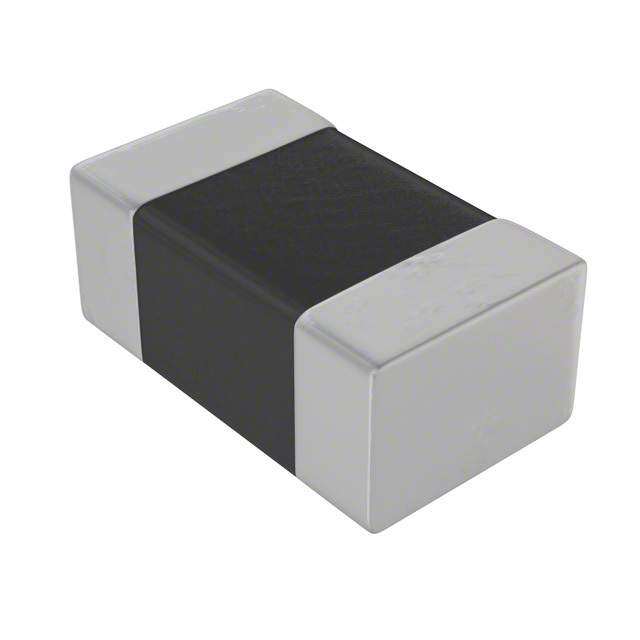
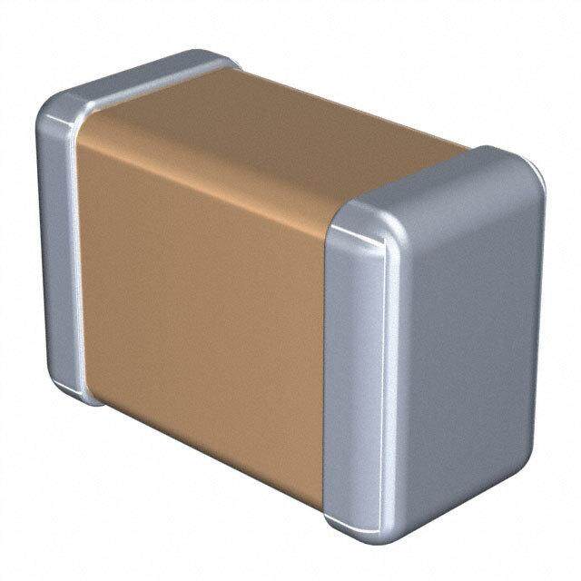
- 型号: CGA7K1X7R3D471M130KA
- 制造商: TDK
- 库位|库存: xxxx|xxxx
- 要求:
| 数量阶梯 | 香港交货 | 国内含税 |
| +xxxx | $xxxx | ¥xxxx |
查看当月历史价格
查看今年历史价格
CGA7K1X7R3D471M130KA产品简介:
ICGOO电子元器件商城为您提供CGA7K1X7R3D471M130KA由TDK设计生产,在icgoo商城现货销售,并且可以通过原厂、代理商等渠道进行代购。 CGA7K1X7R3D471M130KA价格参考。TDKCGA7K1X7R3D471M130KA封装/规格:陶瓷电容器, 470pF ±20% 2000V(2kV) 陶瓷电容器 X7R 1808(4520 公制)。您可以下载CGA7K1X7R3D471M130KA参考资料、Datasheet数据手册功能说明书,资料中有CGA7K1X7R3D471M130KA 详细功能的应用电路图电压和使用方法及教程。
| 参数 | 数值 |
| 产品目录 | |
| 描述 | CAP CER 470PF 2KV 20% X7R 1808 |
| 产品分类 | |
| 品牌 | TDK Corporation |
| 数据手册 | |
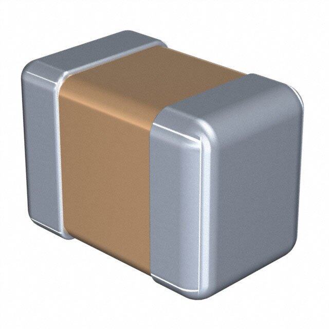
| 产品图片 |
|
| 产品型号 | CGA7K1X7R3D471M130KA |
| rohs | 无铅 / 符合限制有害物质指令(RoHS)规范要求 |
| RoHS指令信息 | |
| 产品系列 | CGA |
| 产品培训模块 | http://www.digikey.cn/PTM/IndividualPTM.page?site=cn&lang=zhs&ptm=26055http://www.digikey.cn/PTM/IndividualPTM.page?site=cn&lang=zhs&ptm=30284 |
| 其它名称 | 445-13085-1 |
| 包装 | 剪切带 (CT) |
| 厚度(最大值) | 0.059"(1.50mm) |
| 大小/尺寸 | 0.177" 长 x 0.079" 宽(4.50mm x 2.00mm) |
| 安装类型 | 表面贴装,MLCC |
| 容差 | ±20% |
| 封装/外壳 | 1808(4520 公制) |
| 工作温度 | -55°C ~ 125°C |
| 应用 | 自动 |
| 引线形式 | - |
| 引线间距 | - |
| 标准包装 | 1 |
| 温度系数 | X7R |
| 特性 | - |
| 特色产品 | http://www.digikey.com/cn/zh/ph/TDK/CGA-series-cap.html |
| 电压-额定 | 2000V(2kV) |
| 电容 | 470pF |
| 等级 | AEC-Q200 |
| 视频文件 | http://www.digikey.cn/classic/video.aspx?PlayerID=1364138032001&width=640&height=505&videoID=3113360146001 |
| 高度-安装(最大值) | - |





- 商务部:美国ITC正式对集成电路等产品启动337调查
- 曝三星4nm工艺存在良率问题 高通将骁龙8 Gen1或转产台积电
- 太阳诱电将投资9.5亿元在常州建新厂生产MLCC 预计2023年完工
- 英特尔发布欧洲新工厂建设计划 深化IDM 2.0 战略
- 台积电先进制程称霸业界 有大客户加持明年业绩稳了
- 达到5530亿美元!SIA预计今年全球半导体销售额将创下新高
- 英特尔拟将自动驾驶子公司Mobileye上市 估值或超500亿美元
- 三星加码芯片和SET,合并消费电子和移动部门,撤换高东真等 CEO
- 三星电子宣布重大人事变动 还合并消费电子和移动部门
- 海关总署:前11个月进口集成电路产品价值2.52万亿元 增长14.8%


PDF Datasheet 数据手册内容提取
MULTILAYER CERAMIC CHIP CAPACITORS December 2018 MULTILAYER CERAMIC CHIP CAPACITORS Automotive grade, high voltage (1,000V and over) CGA series CGA6 3225 [1210 inch] CGA7 4520 [1808 inch] CGA8 4532 [1812 inch] CGA9 5750 [2220 inch] * Dimensions code: JIS[EIA]
(2/7) MULTILAYER CERAMIC CHIP CAPACITORS REMINDERS FOR USING THESE PRODUCTS Before using these products, be sure to request the delivery specifications. SAFETY REMINDERS Please pay sufficient attention to the warnings for safe designing when using this products. REMINDERS 1. The products listed in this specification are intended for use in automotive applications under normal operation and usage conditions. The products are not designed or warranted to meet the requirements of the applications listed below, whose performance and/or quality requires a more stringent level of safety or reliability, or whose failure, malfunction or defect could cause serious damage to society, person or property. Please understand that we are not responsible for any damage or liability caused by use of the products in any of the applications below or for any other use exceeding the range or conditions set forth in this specification sheet. If you intend to use the products in the applications listed below or if you have special requirements exceeding the range or conditions set forth in this specification, please contact us. (1) Aerospace/aviation equipment (8) Public information-processing equipment (2) Transportation equipment (electric trains, ships, etc.) (9) Military equipment (3) Medical equipment (excepting Pharmaceutical Affairs Law (10) Electric heating apparatus, burning equipment classification Class1,2) (11) Disaster prevention/crime prevention equipment (4) Power-generation control equipment (12) Safety equipment (5) Atomic energy-related equipment (13) Other applications that are not considered general-purpose (6) Seabed equipment applications (7) Transportation control equipment When designing your equipment even for general-purpose applications, you are kindly requested to take into consideration securing protection circuit/device or providing backup circuits in your equipment. In addition, although the products listed in this specification are intended for use in automotive applications as described above, they are not prohibited to use in general electronic equipment, whose performance and/or quality doesn’t require a more stringent level of safety or reliability, or whose failure, malfunction or defect could not cause serious damage to society, person or property. Therefore, the description of this caution will be applied, when the products are used in general electronic equipment under a normal operation and usage conditions. 2. We may modify products or discontinue production of a product listed in this catalog without prior notification. 3. We provide “Delivery Specification” that explain precautions for the specifications and safety of each product listed in this catalog. We strongly recommend that you exchange these delivery specifications with customers that use one of these products. 4. If you plan to export a product listed in this catalog, keep in mind that it may be a restricted item according to the “Foreign Exchange and For- eign Trade Control Law”. In such cases, it is necessary to acquire export permission in harmony with this law. 5. Any reproduction or transferring of the contents of this catalog is prohibited without prior permission from our company. 6. We are not responsible for problems that occur related to the intellectual property rights or other rights of our company or a third party when you use a product listed in this catalog. We do not grant license of these rights. 7. This catalog only applies to products purchased through our company or one of our company’s official agencies. This catalog does not apply to products that are purchased through other third parties. Notice: Effective January 2013, TDK will use a new catalog number which adds product thickness and packaging specification detail. This new catalog number should be referenced on all catalog orders going forward, and is not applicable for OEM part number orders. Please be aware the last five digits of the catalog number will differ from the item description (internal control number) on the product label. Contact your local TDK Sales representative for more information. (Example) Catalog issued date Catalog number Item description (on delivery label) Prior to January 2013 C1608C0G1E103J(080AA) C1608C0G1E103JT000N January 2013 and later C1608C0G1E103J080AA C1608C0G1E103JT000N 20181227 / mlcc_automotive_highvoltage_en.fm
(3/7) MULTILAYER CERAMIC CHIP CAPACITORS CGA series Cl Pb Br High voltage (1,000V and over) RoHS REACH Halogen Lead SVHC-Free Free Free Type: CGA6/3225 [1210 inch], CGA7/4520 [1808 inch], CGA8/4532 [1812 inch], CGA9/5750 [2220 inch] ■SERIES OVERVIEW High voltage CGA series, automotive grade of TDK's multilayer ceramic chip capacitor, is a product which has realized the high withstanding volt- age characteristic by the unique inner structure. Voltage rating of 1,000V to 3,000V with capacitance range up to 33nF. ■FEATURES ■APPLICATIONS • Voltage rating of 1,000V, 2,000V and 3,000V (cid:129) Wireless Charging units such as DC-DC converter, Inverter, On board (cid:129) Operating temperature range: –55 to +125°C charger. (cid:129) C0G temperature characteristic which has excellent stable tempera- (cid:129) Decoupling, snubber and resonant circuit and so on of high voltage ture and DC-bias characteristcs is applicable. circuit. (cid:129) AEC-Q200 compliant. ■SHAPE & DIMENSIONS ■CAUTIONS Slit to improve L W washing flux T C P G B SD L Body length PB PA W Body width (cid:129) A slit of about 1mm on the circuit board is recommended to improve T Body height removal of the flux after soldering. B Terminal width (cid:129) Ensure that this product is completely dried following washing. G Terminal spacing (cid:129) Because this product will be subjected to high voltages, use only low- activity rosin flux (with 0.2% max. of chlorine). (cid:129) Using this product with aluminum circuit boards must be considered a special implementation because the high heat stress levels are involved. In case of using aluminum circuit boards, please contact TDK. Dimensions in mm Type L W T B CGA6 3.20±0.40 2.50±0.30 2.50±0.30 0.20 min. CGA7 4.50±0.40 2.00±0.20 2.00±0.20 0.20 min. CGA8 4.50±0.40 3.20±0.40 2.50±0.30 0.20 min. CGA9 5.70±0.40 5.00±0.40 2.80±0.30 0.20 min. Dimensional tolerances are typical values. Please be sure to request delivery specifications that provide further details on the features and specifications of the products for proper and safe use. Please note that the contents may change without any prior notice due to reasons such as upgrading. 20181227 / mlcc_automotive_highvoltage_en.fm
(4/7) MULTILAYER CERAMIC CHIP CAPACITORS ■CATALOG NUMBER CONSTRUCTION CGA 9 Q 1 C0G 3A 333 J 280 K C (1) (2) (3) (4) (5) (6) (7) (8) (9) (10) (11) (1) Series (6) Rated voltage (DC) Code Voltage (DC) (2) Dimensions L x W (mm) 3A 1,000V Code EIA Length Width Terminal width 3D 2,000V 6 CC1210 3.20 2.50 0.20min. 3F 3,000V 7 CC1808 4.50 2.00 0.20min. 8 CC1812 4.50 3.20 0.20min. (7) Nominal capacitance (pF) 9 CC2220 5.70 5.00 0.20min. The capacitance is expressed in three digit codes and in units of pico Farads (pF). The first and second digits identify the first and (3) Thickness code second significant figures of the capacitance. The third digit identi- Code Thickness fies the multiplier. R designates a decimal point. F 0.85 mm G 1.10 mm (Example)0R5 = 0.5pF K 1.30 mm 101 = 100pF L 1.60 mm 225 = 2,200,000pF = 2.2µF M 2.00 mm N 2.30 mm (8) Capacitance tolerance P 2.50 mm Code Tolerance Q 2.80 mm F ±1pF J ±5% (4) Voltage condition for life test K ±10% Symbol Condition M ±20% 1 1 × R.V. (9) Thickness (5) Temperature characteristics Code Thickness Temperature Temperature coefficient 085 0.85 mm Temperature range characteristics or capacitance change 110 1.10 mm C0G 0±30 ppm/°C –55 to +125°C 130 1.30 mm X7R ±15% –55 to +125°C 160 1.60 mm 200 2.00 mm 230 2.30 mm 250 2.50 mm 280 2.80 mm (10) Packaging style Code Style A 178mm reel, 4mm pitch K 178mm reel, 8mm pitch (11) Special reserved code Code Description A,C TDK internal code Please be sure to request delivery specifications that provide further details on the features and specifications of the products for proper and safe use. Please note that the contents may change without any prior notice due to reasons such as upgrading. 20181227 / mlcc_automotive_highvoltage_en.fm
(5/7) MULTILAYER CERAMIC CHIP CAPACITORS Capacitance range chart CGA6/3225 [1210 inch] Capacitance C0G 3A (pF) Code (1kV) 1,000 102 1,200 122 1,500 152 1,800 182 2,200 222 2,700 272 3,300 332 3,900 392 4,700 472 5,600 562 6,800 682 8,200 822 10,000 103 12,000 123 15,000 153 18,000 183 22,000 223 Standard thickness 2.00 mm 2.30 mm 2.50 mm Background gray: The product which is not recommended to a new design. ■ Please refer to the capacitance range table at P-7 for the details such as product thickness and capacitance tolerance. Capacitance range chart CGA7/4520 [1808 inch] Capacitance C0G X7R 3F 3D 3A (pF) Code (3kV) (2kV) (1kV) 10 100 12 120 15 150 18 180 22 220 27 270 33 330 39 390 47 470 56 560 68 680 82 820 100 101 470 471 1,000 102 Standard thickness 0.85 mm 1.10 mm 1.30 mm 1.60 mm 2.00 mm Background gray: The product which is not recommended to a new design. ■ Please refer to the capacitance range table at P-7 for the details such as product thickness and capacitance tolerance. Please be sure to request delivery specifications that provide further details on the features and specifications of the products for proper and safe use. Please note that the contents may change without any prior notice due to reasons such as upgrading. 20181227 / mlcc_automotive_highvoltage_en.fm
(6/7) MULTILAYER CERAMIC CHIP CAPACITORS Capacitance range chart CGA8/4532 [1812 inch] Capacitance C0G X7R 3F 3D 3A (pF) Code (3kV) (2kV) (1kV) 100 101 120 121 150 151 180 181 220 221 270 271 330 331 2,200 222 4,700 472 10,000 103 Standard thickness 1.30 mm 1.60 mm 2.00 mm 2.30 mm 2.50 mm Background gray: The product which is not recommended to a new design. ■ Please refer to the capacitance range table at P-7 for the details such as product thickness and capacitance tolerance. Capacitance range chart CGA9/5750 [2220 inch] Capacitance C0G 3A (pF) Code (1kV) 10,000 103 12,000 123 15,000 153 18,000 183 22,000 223 27,000 273 33,000 333 Standard thickness 2.80 mm Background gray: The product which is not recommended to a new design. ■ Please refer to the capacitance range table at P-7 for the details such as product thickness and capacitance tolerance. Please be sure to request delivery specifications that provide further details on the features and specifications of the products for proper and safe use. Please note that the contents may change without any prior notice due to reasons such as upgrading. 20181227 / mlcc_automotive_highvoltage_en.fm
(7/7) MULTILAYER CERAMIC CHIP CAPACITORS Capacitance range table Temperature characteristics: C0G (–55 to +125°C, 0±30ppm/°C) Thickness Capacitance Catalog number Capacitance Dimensions (mm) tolerance Rated voltage Edc: 3kV Rated voltage Edc: 1kV 10pF 4520 0.85±0.15 ±1pF CGA7F1C0G3F100F085KA 12pF 4520 0.85±0.15 ±10% CGA7F1C0G3F120K085KA 15pF 4520 1.10±0.20 ±10% CGA7G1C0G3F150K110KA 18pF 4520 1.10±0.20 ±10% CGA7G1C0G3F180K110KA 22pF 4520 1.10±0.20 ±10% CGA7G1C0G3F220K110KA 27pF 4520 1.60±0.20 ±10% CGA7L1C0G3F270K160KA 33pF 4520 1.60±0.20 ±10% CGA7L1C0G3F330K160KA 39pF 4520 1.60±0.20 ±10% CGA7L1C0G3F390K160KA 47pF 4520 1.60±0.20 ±10% CGA7L1C0G3F470K160KA 56pF 4520 2.00±0.20 ±10% CGA7M1C0G3F560K200KA 68pF 4520 2.00±0.20 ±10% CGA7M1C0G3F680K200KA 82pF 4520 2.00±0.20 ±10% CGA7M1C0G3F820K200KA 4520 2.00±0.20 ±10% CGA7M1C0G3F101K200KA 100pF 4532 1.60±0.20 ±10% CGA8L1C0G3F101K160KA 120pF 4532 1.60±0.20 ±10% CGA8L1C0G3F121K160KA 150pF 4532 1.60±0.20 ±10% CGA8L1C0G3F151K160KA 180pF 4532 1.60±0.20 ±10% CGA8L1C0G3F181K160KA 220pF 4532 2.00±0.20 ±10% CGA8M1C0G3F221K200KA 270pF 4532 2.30±0.20 ±10% CGA8N1C0G3F271K230KA 330pF 4532 2.50±0.30 ±10% CGA8P1C0G3F331K250KA 1nF 3225 2.00±0.20 ±5% CGA6M1C0G3A102J200AC 1.2nF 3225 2.00±0.20 ±5% CGA6M1C0G3A122J200AC 1.5nF 3225 2.00±0.20 ±5% CGA6M1C0G3A152J200AC 1.8nF 3225 2.00±0.20 ±5% CGA6M1C0G3A182J200AC 2.2nF 3225 2.00±0.20 ±5% CGA6M1C0G3A222J200AC 2.7nF 3225 2.00±0.20 ±5% CGA6M1C0G3A272J200AC 3.3nF 3225 2.00±0.20 ±5% CGA6M1C0G3A332J200AC 3.9nF 3225 2.00±0.20 ±5% CGA6M1C0G3A392J200AC 4.7nF 3225 2.00±0.20 ±5% CGA6M1C0G3A472J200AC 5.6nF 3225 2.00±0.20 ±5% CGA6M1C0G3A562J200AC 6.8nF 3225 2.00±0.20 ±5% CGA6M1C0G3A682J200AC 8.2nF 3225 2.30±0.20 ±5% CGA6N1C0G3A822J230AC 3225 2.50±0.30 ±5% CGA6P1C0G3A103J250AC 10nF 5750 2.80±0.30 ±5% CGA9Q1C0G3A103J280KC 3225 2.50±0.30 ±5% CGA6P1C0G3A123J250AC 12nF 5750 2.80±0.30 ±5% CGA9Q1C0G3A123J280KC 3225 2.50±0.30 ±5% CGA6P1C0G3A153J250AC 15nF 5750 2.80±0.30 ±5% CGA9Q1C0G3A153J280KC 3225 2.50±0.30 ±5% CGA6P1C0G3A183J250AC 18nF 5750 2.80±0.30 ±5% CGA9Q1C0G3A183J280KC 3225 2.50±0.30 ±5% CGA6P1C0G3A223J250AC 22nF 5750 2.80±0.30 ±5% CGA9Q1C0G3A223J280KC 27nF 5750 2.80±0.30 ±5% CGA9Q1C0G3A273J280KC 33nF 5750 2.80±0.30 ±5% CGA9Q1C0G3A333J280KC ■Gray item: The product which is not recommended to a new design. Capacitance range table Temperature characteristics: X7R (–55 to +125°C, ±15%) Thickness Capacitance Catalog number Capacitance Dimensions (mm) tolerance Rated voltage Edc: 2kV Rated voltage Edc: 1kV ±10% CGA7K1X7R3D471K130KA CGA7K1X7R3A471K130KA 470pF 4520 1.30±0.20 ±20% CGA7K1X7R3D471M130KA CGA7K1X7R3A471M130KA ±10% CGA7K1X7R3D102K130KA CGA7K1X7R3A102K130KA 1nF 4520 1.30±0.20 ±20% CGA7K1X7R3D102M130KA CGA7K1X7R3A102M130KA ±10% CGA8K1X7R3D222K130KA 2.2nF 4532 1.30±0.20 ±20% CGA8K1X7R3D222M130KA ±10% CGA8L1X7R3A472K160KA 4.7nF 4532 1.60±0.20 ±20% CGA8L1X7R3A472M160KA ±10% CGA8M1X7R3A103K200KA 10nF 4532 2.00±0.20 ±20% CGA8M1X7R3A103M200KA Please be sure to request delivery specifications that provide further details on the features and specifications of the products for proper and safe use. Please note that the contents may change without any prior notice due to reasons such as upgrading. 20181227 / mlcc_automotive_highvoltage_en.fm
 Datasheet下载
%2015.jpg)

