ICGOO在线商城 > 电路保护 > TVS - 变阻器,MOV > CG0603MLC-12E
 Datasheet下载
- 型号: CG0603MLC-12E
- 制造商: Bourns
- 库位|库存: xxxx|xxxx
- 要求:
| 数量阶梯 | 香港交货 | 国内含税 |
| +xxxx | $xxxx | ¥xxxx |
查看当月历史价格
查看今年历史价格
CG0603MLC-12E产品简介:
ICGOO电子元器件商城为您提供CG0603MLC-12E由Bourns设计生产,在icgoo商城现货销售,并且可以通过原厂、代理商等渠道进行代购。 CG0603MLC-12E价格参考¥0.64-¥3.76。BournsCG0603MLC-12E封装/规格:TVS - 变阻器,MOV, Varistor 1 Circuit Surface Mount, MLCV 0603 (1608 Metric)。您可以下载CG0603MLC-12E参考资料、Datasheet数据手册功能说明书,资料中有CG0603MLC-12E 详细功能的应用电路图电压和使用方法及教程。
Bourns Inc. 的 CG0603MLC-12E 是一款 TVS(瞬态电压抑制器)变阻器,具体属于金属氧化物压敏电阻 (MOV) 类别。该型号的应用场景主要集中在以下几个方面:

 1. 过电压保护
CG0603MLC-12E 主要用于电路中的过电压保护。它能够在短时间内承受高能量的瞬态电压冲击,并将这些瞬态电压钳位到一个安全水平,从而保护后端电路免受损坏。例如,在电源线、信号线等易受雷击或电磁干扰影响的环境中,该元件可以有效防止瞬态高压对敏感电子设备的损害。

 2. 消费电子设备
在消费电子产品中,如智能手机、平板电脑、笔记本电脑等,CG0603MLC-12E 可以安装在 USB 接口、充电接口等位置,防止静电放电 (ESD) 和其他瞬态电压对内部电路的影响。此外,它还可以用于音频设备、显示器等产品中,确保设备在面对突发电压波动时的安全性和稳定性。

 3. 工业自动化
在工业自动化领域,特别是在工厂车间、电力系统等环境中,设备常常面临复杂的电气环境和频繁的电压波动。CG0603MLC-12E 可以用于保护传感器、控制器、通信模块等关键组件,避免因瞬态电压导致的设备故障或停机,提高系统的可靠性和安全性。

 4. 通信设备
通信设备如路由器、交换机、基站等,通常需要在恶劣的环境下工作,可能会受到雷击、电网波动等因素的影响。CG0603MLC-12E 可以安装在这些设备的关键部位,如天线接口、电源输入端等,提供有效的过电压保护,确保通信链路的稳定性和数据传输的可靠性。

 5. 汽车电子
在汽车电子系统中,如车载娱乐系统、导航系统、发动机控制单元 (ECU) 等,CG0603MLC-12E 可以用于保护这些系统免受电池电压波动、点火噪声等瞬态电压的影响,确保车辆电子系统的正常运行。

总的来说,CG0603MLC-12E 适用于各种需要过电压保护的场合,尤其适合那些对瞬态电压敏感的电子设备和系统,能够有效提高设备的可靠性和使用寿命。
| 参数 | 数值 |
| 产品目录 | |
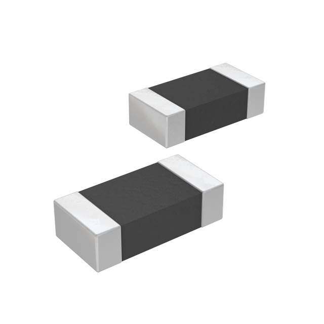
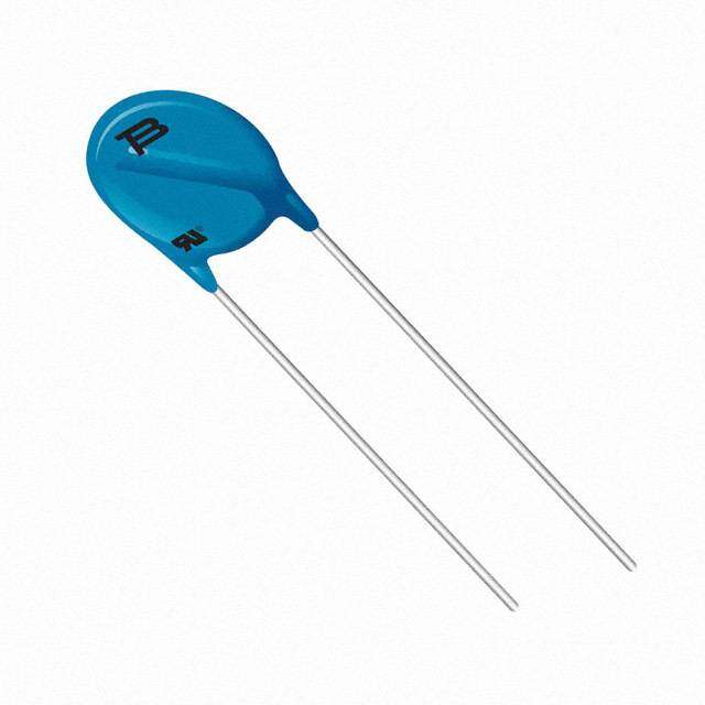
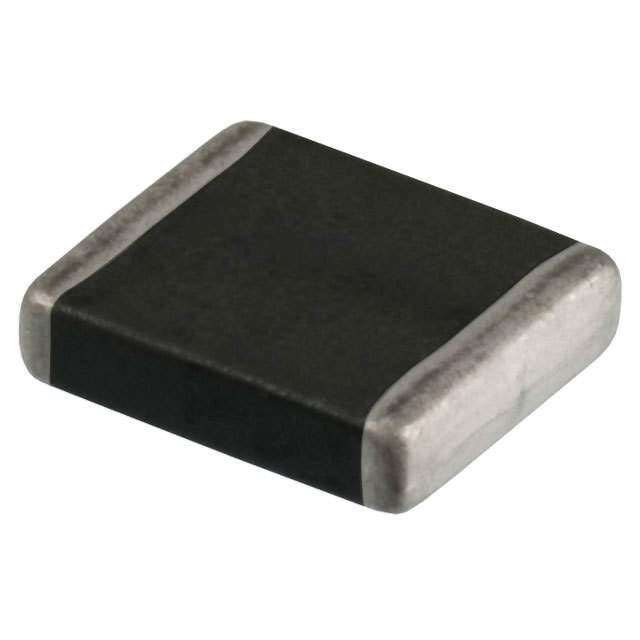
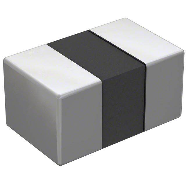
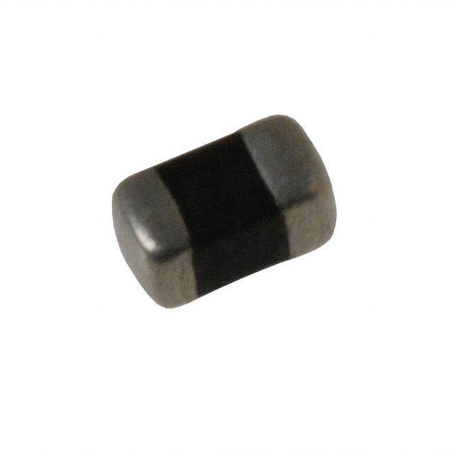
| 描述 | VARISTOR 0603压敏电阻 Chip Guard 0603 12 Volts |
| 产品分类 | |
| 品牌 | Bourns Inc. |
| 产品手册 | |
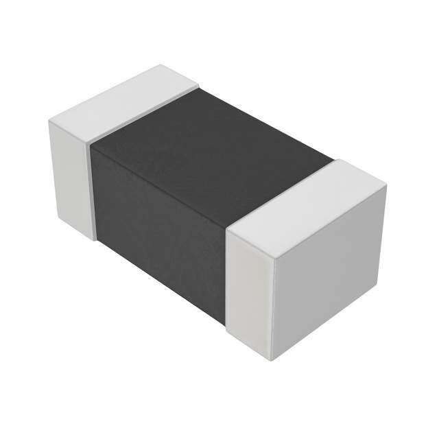
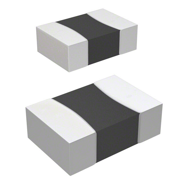
| 产品图片 |
|
| rohs | 符合RoHS无铅 / 符合限制有害物质指令(RoHS)规范要求 |
| 产品系列 | Bourns CG0603MLC-12EChipGuard® |
| mouser_ship_limit | 该产品可能需要其他文件才能进口到中国。 |
| 数据手册 | |
| 产品型号 | CG0603MLC-12E |
| 产品 | MLV |
| 产品目录绘图 |
|
| 产品种类 | 压敏电阻 |
| 其它名称 | CG0603MLC-12EDKR |
| 包装 | Digi-Reel® |
| 变阻器电压 | - |
| 商标 | Bourns |
| 商标名 | ChipGuard |
| 外壳代码-in | 0603 |
| 外壳代码-mm | 1608 |
| 外壳宽度 | 0.8 mm |
| 安装 | SMD/SMT |
| 宽度 | 0.8 mm |
| 封装 | Reel |
| 封装/外壳 | 0603(1608 公制) |
| 封装/箱体 | 0603 (1608 metric) |
| 尺寸 | 0.8 mm W x 1.6 mm L x 0.8 mm H |
| 工作温度范围 | - 40 C to + 85 C |
| 工作电压 | 12 V |
| 工厂包装数量 | 5000 |
| 最大AC电压 | - |
| 最大DC电压 | 12VDC |
| 标准包装 | 1 |
| 电压 | 12 V |
| 电压额定值DC | 12 V |
| 电容 | 0.5 pF |
| 电流-浪涌 | - |
| 电流额定值 | 50 nA |
| 电路数 | 1 |
| 端接类型 | SMD/SMT |
| 系列 | MLC |
| 能量 | - |
| 通道 | 1 Channel |
| 钳位电压 | 30 V |


Series%20Top.jpg)
Series%20Side.jpg)


- 商务部:美国ITC正式对集成电路等产品启动337调查
- 曝三星4nm工艺存在良率问题 高通将骁龙8 Gen1或转产台积电
- 太阳诱电将投资9.5亿元在常州建新厂生产MLCC 预计2023年完工
- 英特尔发布欧洲新工厂建设计划 深化IDM 2.0 战略
- 台积电先进制程称霸业界 有大客户加持明年业绩稳了
- 达到5530亿美元!SIA预计今年全球半导体销售额将创下新高
- 英特尔拟将自动驾驶子公司Mobileye上市 估值或超500亿美元
- 三星加码芯片和SET,合并消费电子和移动部门,撤换高东真等 CEO
- 三星电子宣布重大人事变动 还合并消费电子和移动部门
- 海关总署:前11个月进口集成电路产品价值2.52万亿元 增长14.8%
PDF Datasheet 数据手册内容提取
NT *RoHS VCEOARVMSIAPILOLINAASBLE Features Applications NT MPLIA n RoHS compliant* n HDMI 1.4 HS CO n ESD protection >25 kV n Digital Visual Interface (DVI) Ro n Low capacitance <0.5 pF n USB 3.0 / USB OTG * n Low leakage current <50 nA n Memory protection n SIM card ports REE D F LEA ChipGuard® MLC Series - ESD Protectors General Information Device Symbol TedDDlehiVessecIci tghoCrnoarh enrIigEpdiceGE t)coE uoE a1pmSr3rdopD9®to4 e sMn capetLpe neCpctqsil fiiuS ccfiarepaotrmtimioieoens nens shl.te attcaostr rIgboEeesCtetea6ndt1 ic s0fL poVdE0REeAroRi0 DHs SchIS-F cOi4RiCfigNEhO-SEc ha2MAaP Rr,LsIlE g lALypeNeT e d*vdeeeadslm iU4ga nS(g±eBe8d . 3 ktTo.V0h p /eCUr oMoStnBeLtcC aOtc fsTta e/Gm n±,si 1lHyit5 iDvh keaMV sI A b1ie.r4 e,n V The ChipGuard® MLC Series has been manufactured to provide low 0.5 pF capacitance aanlmdo lseta tkraagnesp caurrernetn utsn ldeesrs nthoarmn a5l wnAo rwkiinthg ecxocnedllietionnt sc.lamp qual*iRtoie&H SsA EC,CO mAMPPPLaIRAkONVTiEnDg the family Electrical Characteristics @ 25 °C (unless otherwise noted) CG0402MLC- PTTMyyaapprxaiiccimmaallue CCmteol arCnmtaipnpiuanocgui tVsa onOlctpaeeg @rea t(1iNn goV tRVe Mo1l)tSa g1e M Hz SyVCVmDCObCol 33.3.L3G 055LG 112L2G 224L4G*R o20HRS5. 5OCV3OE.MD33 P(LL.SI3eGAleNAcTt Model0s)5L5GA 121L2GA 242L4GA UpVVnFit Maximum Leakage Current @ Max. VDC IL AEC APP5 nA Typical Trigger Voltage (Note 2) VT 250 V Maximum Response Time RT 1 ns ESD Protection: Per IEC 61000-4-2 Level 4 Min. Contact Discharge ±8 kV Min. Air Discharge ±15 (Note 3) kV Min. Air Discharge ±25 kV Operating Temperature TOPR -40 to +85 -40 to +125 ˚C Storage Temperature TSTG -55 to +150 ˚C CG0603MLC- Parameter Symbol Unit 3.3LE 05LE 12LE 24LE 3.3LEA 05LEA 12LEA 24LEA Typical Continuous Operating Voltage VDC 3.3 5 12 24 3.3 5 12 24 V Typical Clamping Voltage (Note 1) VC 25 25 25 V Maximum Capacitance @ 1 VRMS 1 MHz CO 0.5 pF Maximum Leakage Current @ Max. VDC IL 5 5 5 nA Typical Trigger Voltage (Note 2) VT 250 250 250 V Maximum Response Time RT 1 ns ESD Protection: Per IEC 61000-4-2 Level 4 Min. Contact Discharge ±8 kV Min. Air Discharge ±15 (Note 3) kV Min. Air Discharge ±25 kV Operating Temperature TOPR -40 to +85 -40 to +125 ˚C Storage Temperature TSTG -55 to +150 ˚C Notes: 1. Per IEC 61000-4-2, Level 4 8 kV Contact Discharge. Measurement 30 ns after initiation of pulse. 2. Per IEC 61000-4-2, Level 4 8 kV Contact Discharge. Measurement at maximum pulse voltage. 3. IEC 61000-4-2 ESD Performance will meet minimum 1000 reps without degradation in performance. *RoHS Directive 2002/95/EC Jan. 27, 2003 including annex and RoHS Recast 2011/65/EU June 8, 2011. Specifications are subject to change without notice. The device characteristics and parameters in this data sheet can and do vary in different applications and actual device performance may vary over time. Users should verify actual device performance in their specific applications.
W A L ChipGuard® MLC Series - ESD Protectors W Product Dimensions Recommended Pad Layout C B A A D L W B A L MM DIMENSIONS: C B (INCHES) A D CG0402 CG0603 CG0402 CG0603 Dimension Series C Series B Dim. Series Series A B 1.00 ± 0.15 1.6D0 ± 0.20 0.51 0.76 L A (0.04 ± 0.006) (0.064 ± 0.008) (0.020) (0.030) 0.50 ± 0.10 0.80 ± 0.20 0.61 1.02 W B (0.02 ± 0.004) (0.032 ± 0.008) (0.024) (0.040) B 0.36 ± 0.05 0.45 ± 0.10 0.51 0.50 A C (0.014 ± 0.002) (0.018 ± 0.004) (0.020) (0.020) 0.25 ± 0.15 0.30 ± 0.20 1.70 2.54 B D (0.10 ± 0.006) (0.012 ± 0.008) (0.067) (0.100) Solder Reflow Recommendations 300 Preheat Stages 1-3 Soldering Cooling A Stage 1 Preheat Ambient to Preheating 30 s to 60 s 250 Temperature 200 B Stage 2 Preheat 140 °C to 160 °C 60 s to 120 s mperature (C)ϒ 115000 CD SM taaigne H 3e aPtrienhge at P2201re00h °°eCCa t to 200 °C 265005 sss tttooo 476005 sss Te 220 °C 50 s to 60 s 50 230 °C 40 s to 50 s 240 °C 30 s to 40 s 0 250 °C to 255 °C 5 s 110 sec. (min.) 30-70 120 sec. (min.) E Cooling 200 °C to 100 °C 1 °C/s to 4 °C/s sec. Time (seconds) • This product can be damaged by rapid heating, cooling or localized heating. • Heat shocks should be avoided. Preheating and gradual cooling recommended. • Excessive solder can damage the device. Print solder thickness of 150 to 200 um recommended. • Solder gun tip temperature should be kept below 280 °C and should not touch the device directly. Contact should be less than 3 seconds. A solder gun under 30 watts is recommended. Specifications are subject to change without notice. The device characteristics and parameters in this data sheet can and do vary in different applications and actual device performance may vary over time. Users should verify actual device performance in their specific applications.
ChipGuard® MLC Series - ESD Protectors Packaging Dimensions 13.0 ± 1.0 8.00 ± 0.30 (0.52 ± 0.04) (0.32 ± 0.012) 4.00 ± 0.10 C (0.16 ± 0.004) 1.50 ± 0.10 (0.06 ± 0.004) 2.0 ± 0.50 62.0 ± 1.50 (2.48 ± 0.06) (0.08 ± 0.02) L 13.0 ± 0.50 (0.52 ± 0.02) TOP G D TAPE 21.0 ± 0.80 3.50 ± 0.05 (0.84 ± 0.032) 180.8 ± 2.0 W (0.14 ± 0.002) (7.12 ± 0.08) NOTES: TAPE MATERIAL IS PAPER. TAPE THICKNESS IS 0.48 ± 0.03 MM (0.019 ± 0.0012) DIMENSIONS: (INCHES) COVER TAPE ADHESION IS 40 ± 15 GRAMS. 9.0 ± 0.50 (0.36 ± 0.02) CG0402 CG0603 How to Order Dimension Series Series CG 0n0n MLC - n.n x x x 1.75 ± 0.05 1.75 ± 0.10 C ChipGuard® (0.04 ± 0.002) (0.04 ± 0.004) Product Designator 2.00 ± 0.02 2.00 ± 0.05 Package Option D 0402 = 0402 Package (0.08 ± 0.0008) (0.08 ± 0.002) 0603 = 0603 Package 1.12 ± 0.03 1.80 ± 0.20 Multilayer Series Designator L (0.045 ± 0.0012) (0.072 ± 0.008) Operating Voltage** 3.3 = 3.3 V 0.62 ± 0.03 0.90 ± 0.20 05 = 5 V W (0.025 ± 0.0012) (0.036 ± 0.008) 12 = 12 V 24 = 24 V G 2.0 ± 0.05 4.0 ± 0.05 Low Leakage Current Option (0.08 ± 0.002) (0.16 ± 0.002) L = Low Leakage Current Blank = Standard Product Tape & Reel Packaging E = 5,000 pcs. per reel (0603 Package) G = 10,000 pcs. per reel (0402 Package) Operating Temperature Option A = Higher +125 °C Operating Temperature Blank = Standard Product ** Only models lower than 10 volts require decimal point. Asia-Pacific: Tel: +886-2 2562-4117 • Email: asiacus@bourns.com EMEA: Tel: +36 88 520 390 • Email: eurocus@bourns.com The Americas: Tel: +1-951 781-5500 • Email: americus@bourns.com www.bourns.com REV. T 01/17 Specifications are subject to change without notice. The device characteristics and parameters in this data sheet can and do vary in different applications and actual device performance may vary over time. Users should verify actual device performance in their specific applications.