ICGOO在线商城 > CD0603-Z8V2
- 型号: CD0603-Z8V2
- 制造商: Bourns
- 库位|库存: xxxx|xxxx
- 要求:
| 数量阶梯 | 香港交货 | 国内含税 |
| +xxxx | $xxxx | ¥xxxx |
查看当月历史价格
查看今年历史价格
CD0603-Z8V2产品简介:
ICGOO电子元器件商城为您提供CD0603-Z8V2由Bourns设计生产,在icgoo商城现货销售,并且可以通过原厂、代理商等渠道进行代购。 提供CD0603-Z8V2价格参考以及BournsCD0603-Z8V2封装/规格参数等产品信息。 你可以下载CD0603-Z8V2参考资料、Datasheet数据手册功能说明书, 资料中有CD0603-Z8V2详细功能的应用电路图电压和使用方法及教程。
| 参数 | 数值 |
| 产品目录 | |
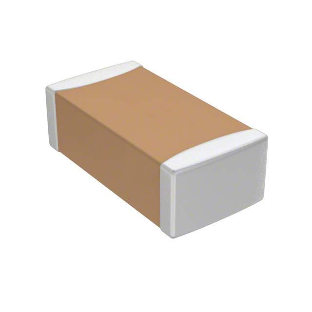
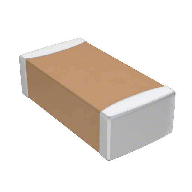
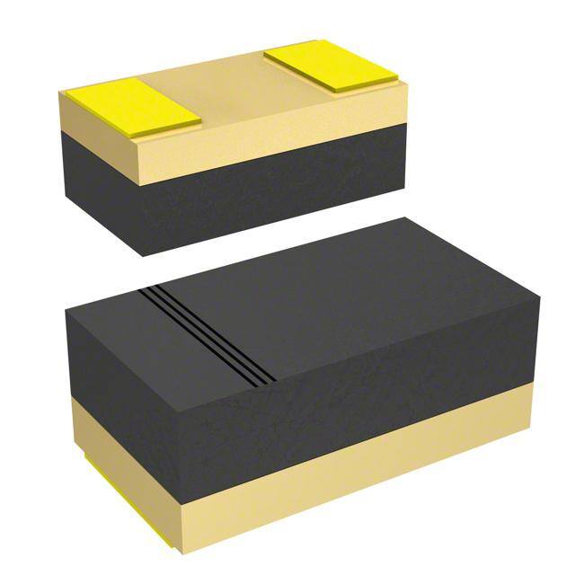
| 描述 | DIODE ZENER 8.2V 150MW 0603稳压二极管 ZENER DIODE 8.2VOLT |
| 产品分类 | 单二极管/齐纳分离式半导体 |
| 品牌 | Bourns |
| 产品手册 | |
| 产品图片 |
|
| rohs | 符合RoHS无铅 / 符合限制有害物质指令(RoHS)规范要求 |
| 产品系列 | 二极管与整流器,稳压二极管,Bourns CD0603-Z8V2- |
| 数据手册 | |
| 产品型号 | CD0603-Z8V2 |
| 不同If时的电压-正向(Vf) | - |
| 不同 Vr时的电流-反向漏电流 | 100nA @ 6V |
| 产品种类 | |
| 供应商器件封装 | 0603 |
| 功率-最大值 | 150mW |
| 功率耗散 | 150 mW |
| 包装 | 带卷 (TR) |
| 商标 | Bourns |
| 安装类型 | 表面贴装 |
| 安装风格 | SMD/SMT |
| 容差 | ±5% |
| 封装 | Reel |
| 封装/外壳 | 0603(1608 公制) |
| 封装/箱体 | 0603 |
| 工作温度 | -55°C ~ 125°C |
| 工厂包装数量 | 4000 |
| 最大反向漏泄电流 | 100 nA |
| 最大工作温度 | + 125 C |
| 最大齐纳阻抗 | 7 Ohms |
| 最小工作温度 | - 55 C |
| 标准包装 | 4,000 |
| 电压-齐纳(标称值)(Vz) | 8.2V |
| 电压容差 | 5 % |
| 配置 | Single |
| 阻抗(最大值)(Zzt) | 7 欧姆 |
| 齐纳电压 | 8.2 V |



- 商务部:美国ITC正式对集成电路等产品启动337调查
- 曝三星4nm工艺存在良率问题 高通将骁龙8 Gen1或转产台积电
- 太阳诱电将投资9.5亿元在常州建新厂生产MLCC 预计2023年完工
- 英特尔发布欧洲新工厂建设计划 深化IDM 2.0 战略
- 台积电先进制程称霸业界 有大客户加持明年业绩稳了
- 达到5530亿美元!SIA预计今年全球半导体销售额将创下新高
- 英特尔拟将自动驾驶子公司Mobileye上市 估值或超500亿美元
- 三星加码芯片和SET,合并消费电子和移动部门,撤换高东真等 CEO
- 三星电子宣布重大人事变动 还合并消费电子和移动部门
- 海关总署:前11个月进口集成电路产品价值2.52万亿元 增长14.8%



PDF Datasheet 数据手册内容提取
NT Features This series is currently available, but not MPLIA RoHS compliant* r e commended for new designs. O HS C Zener voltages 2.0 V to 39 V Ro * Fits SOD323 and SOD523 S 3 CD0603/1005-Z Surface Mount Zener Diode Series General Information The markets of portable communications, computing and video equipment are challenging the semiconductor industry to develop increasingly smaller electronic components. Bourns offers Zener Diodes for voltage reference applications, in compact chip package 0603 and 1005 size format, which offer PCB real estate savings and are considerably smaller than most competitive parts. The Zener Diodes have a zener voltage range between 2.0 V and 39 V. Bourns®Chip Diodes conform to JEDEC standards, are easy to handle on standard pick and place equipment and their flat configuration minimizes roll away. Electrical and Thermal Characteristics (@ TA= 25 °C Unless Otherwise Noted) Parameter Symbol CD1005-Z CD0603-Z Unit Power Dissipation @ T=25(cid:36)C PD 200 150 mW Peak Forward Surge Current 8.3 ms Single Half Sine-wave Superimposed on IFSM 2.0 2.0 A Rated Load (JEDEC Method) Operating and Storage Temperature Range TJ -55to +125 -55to +125 (cid:36)C Notes: 1.Pulse test width PW=300 (cid:43)sec, 1 % duty cycle. 2.Mounted on P.C. board with 0.2 x 0.2 “ (5.0 x 5.0 mm) copper pad areas. How To Order CD 0603 - Z 2V2 Common Code Chip Diode Package (cid:2094) 0603 (cid:2094) 1005 Model Z = Zener Diode Nominal Zener Voltage 2V2 = 2.2 Volts 39 = 39 Volts Asia-Pacific: Tel: +886-2 2562-4117 (cid:2094) Fax: +886-2 2562-4116 EMEA: (cid:59)(cid:76)(cid:83)(cid:33)(cid:3)(cid:18)(cid:26)(cid:29)(cid:3)(cid:31)(cid:31)(cid:3)(cid:28)(cid:25)(cid:23)(cid:3)(cid:26)(cid:32)(cid:23)(cid:3)(cid:2094)(cid:3)(cid:45)(cid:72)(cid:95)(cid:33)(cid:3)(cid:18)(cid:26)(cid:29)(cid:3)(cid:31)(cid:31)(cid:3)(cid:28)(cid:25)(cid:23)(cid:3)(cid:25)(cid:24)(cid:24) The Americas: Tel: +1-951 781-5500 (cid:2094) Fax: +1-951 781-5700 www.bourns.com *RoHS Directive 2002/95/EC Jan. 27, 2003 including annex and RoHS Recast 2011/65/EU June 8, 2011. Specifications are subject to change without notice. The device characteristics and parameters in this data sheet can and do vary in different applications and actual device performance may vary over time. Users should verify actual device performance in their specific applications.
Applications DC-DC converters Portable electronics Industrial controllers Desktop PCs and notebooks CD0603/1005-Z Surface Mount Zener Diode Series Electrical Characteristics (@ TA= 25 °C Unless Otherwise Noted) Zener Voltage Zener Impedance Reverse Current Part Number Part VZ ZZT IZ ZZK IZ IR Marking CD0603 CD1005 Min. V Max. V IZ(mA) Ohms mA Ohms mA (cid:43)A VR -Z2 -Z2 Z0 1.90 2.1 5 100 5 600 1 100 1 -Z2V2 -Z2V2 Z1 2.09 2.31 5 100 5 600 1 100 1 -Z2V4 -Z2V4 Z2 2.28 2.52 5 85 5 600 1 100 1 -Z2V7 -Z2V7 Z3 2.57 2.84 5 83 5 500 1 75 1 -Z3 -Z3 Z4 2.85 3.15 5 95 5 500 1 50 1 -Z3V3 -Z3V3 Z5 3.14 3.47 5 95 5 500 1 25 1 -Z3V6 -Z3V6 Z6 3.42 3.78 5 95 5 500 1 15 1 -Z3V9 -Z3V9 Z7 3.71 4.10 5 95 5 500 1 10 1 -Z4V3 -Z4V3 Z8 4.09 4.52 5 95 5 500 1 5 1 -Z4V7 -Z4V7 Z9 4.47 4.94 5 78 5 500 1 5 2 -Z5V1 -Z5V1 ZA 4.85 5.36 5 60 5 480 1 0.1 0.8 -Z5V6 -Z5V6 ZB 5.32 5.88 5 40 5 400 1 0.1 1 -Z6V2 -Z6V2 ZC 5.89 6.51 5 10 5 200 1 0.1 2 -Z6V8 -Z6V8 ZE 6.46 7.14 5 8 5 150 1 0.1 3 -Z7V5 -Z7V5 ZF 7.13 7.88 5 7 5 50 1 0.1 5 -Z8V2 -Z8V2 ZG 7.79 8.61 5 7 5 50 1 0.1 6 -Z9V1 -Z9V1 ZH 8.65 9.56 5 10 5 50 1 0.1 7 -Z10 -Z10 ZJ 9.50 10.50 5 15 5 70 1 0.1 7.5 -Z11 -Z11 ZK 10.45 11.55 5 20 5 70 1 0.1 8.5 -Z12 -Z12 ZM 11.40 12.60 5 20 5 90 1 0.1 9 -Z13 -Z13 ZN 12.35 13.65 5 25 5 110 1 0.1 10 -Z15 -Z15 ZP 14.25 15.75 5 30 5 110 1 0.1 11 -Z16 -Z16 ZQ 15.20 16.80 5 40 5 170 1 0.1 12 -Z18 -Z18 ZR 17.10 18.90 5 50 5 170 1 0.1 14 -Z20 -Z20 ZS 19.00 21.00 5 50 5 220 1 0.1 15 -Z22 -Z22 ZT 20.90 23.10 5 55 5 220 1 0.1 17 -Z24 -Z24 ZU 22.80 25.20 5 80 5 220 1 0.1 18 -Z27 -Z27 ZV 25.65 28.35 5 80 5 250 1 0.1 20 -Z30 -Z30 ZW 28.50 31.50 5 80 5 250 1 0.1 23 -Z33 -Z33 ZX 31.35 34.65 5 80 5 250 1 0.1 25 -Z36 -Z36 ZY 34.20 37.80 5 90 5 250 1 0.1 27 -Z39 -Z39 ZZ 37.05 40.95 5 90 5 300 1 0.1 39 Specifications are subject to change without notice. The device characteristics and parameters in this data sheet can and do vary in different applications and actual device performance may vary over time. Users should verify actual device performance in their specific applications.
CD0603/1005-Z Surface Mount Zener Diode Series Product Dimensions Recommended Pad Layout A A B B C D Dimension 0603 1005 1.25 2.00 A (Max.) (0.049) (0.079) C 1.00 1.3 B (Min.) (0.039) (0.051) 0.6 0.7 C (Min.) (0.024) (0.028) MM DIMENSIONS: (INCHES) E Physical Specifications Dimension 0603 1005 Case....................................0603(1608) / 1005(2512) Molded plastic 1.60 - 1.80 2.40 - 2.60 A Terminals .........................Gold plated, solderable per MIL-STD-750, (0.063 - 0.071) (0.095 - 0.102) Method 2026 B 0.80 - 1.00 1.10 - 1.30 Polarity ....................................................Indicated by cathode band (0.031 - 0.039) (0.043 - 0.051) Mounting Position ........................................................................Any 0.45 0.50 C Typ. Typ. (0.018) (0.020) 0.70 - 0.85 0.70 - 0.90 D (0.027 - 0.033) (0.027 - 0.035) 0.70 1.00 E Typ. Typ. (0.028) (0.039) MM DIMENSIONS: (INCHES) Specifications are subject to change without notice. The device characteristics and parameters in this data sheet can and do vary in different applications and actual device performance may vary over time. Users should verify actual device performance in their specific applications.
CD0603/1005-Z Surface Mount Zener Diode Series Rating and Characteristic Curves Temperature Sensitivity 7 100 6 mV/°C) 45 V/°C) Coefficient, ( 123 oefficient, (m 10 Temperature ---3210 Temperature C -4 1 2 3 4 5 6 7 8 9 10 11 12 10 20 30 40 50 Nominal Zener Voltage, Volts Nominal Zener Voltage, Volts Zener Current vs. Zener Voltage Characteristics 100 100 TA = 25 °C TA = 25 °C 22V22V42V733V33V63V94V34V75V15V6 6V2 6V8 7V5 8V2 9V1 10 11 12 13 15 16 18 20 22 24 27 30 3338 39 10 10 A) A) m m urrent ( 1 urrent ( 1 C C ner ner Ze 0.1 Ze 0.1 0.01 0.01 0 2 4 6 8 10 12 10 20 30 40 50 Reverse Voltage, Volts Reverse Voltage, Volts Derating Curve Typical Junction Capacitance 0.6 400 TA = 25 °C 350 0.5 W) 300 0 V BIAS wer Dissipation ( 000...234 apacitance (pF) 122505000 1 V BIAS Po C BIASAT 100 50 % OF V2NOM 0.1 50 0 0 0 25 50 75 100 125 150 0 10 20 30 40 Temperature (°C) Normal Zener Voltage (V) Specifications are subject to change without notice. The device characteristics and parameters in this data sheet can and do vary in different applications and actual device performance may vary over time. Users should verify actual device performance in their specific applications.
CD0603/1005-Z Surface Mount Zener Diode Series Rating and Characteristic Curves: Zener Impedance vs. Voltage Forward Current vs. Voltage 1000 1000 TA = 25 °C Iz (AC) 0.1 Iz (DC) F = 1 kHZ Iz = 1 mA s) m Oh 100 A) 100 nce ( Iz = 5 mA nt (m a e mic Imped 10 Iz = 20 mA ward Curr 10 yna For D 1 1 1 10 50 0.4 0.5 0.6 0.7 0.8 0.9 1.0 1.1 Normal Zener Voltage (V) Forward Voltage (V) Specifications are subject to change without notice. The device characteristics and parameters in this data sheet can and do vary in different applications and actual device performance may vary over time. Users should verify actual device performance in their specific applications.
CD0603/1005-Z Surface Mount Zener Diode Series Packaging Information The product will be dispensed in Tape and Reel format (see diagram below). P 0 P1 E T d Index Hole 120 (cid:36) F D2 W B D1 D P A C Trailer Device Leader ....... ....... ....... ....... W1 End ....... ....... ....... ....... Start MM DIMENSIONS: (INCHES) 10 pitches (min.) 10 pitches (min.) Devices are packed in accordance with EIA standard RS-481-A and specifications shown here. Direction of Feed Item Symbol 0603 1005 1.00 ±0.10 1.55 ±0.10 Carrier Width A (0.039 - 0.004) (0.061 - 0.004) 1.85 ±0.10 2.65 ±0.10 Carrier Length B (0.073 - 0.004) (0.104 - 0.004) 1.00 ±0.10 1.05 ±0.10 Carrier Depth C (0.039 - 0.004) (0.041 - 0.004) 1.55 ±0.05 1.55 ±0.10 Sprocket Hole d (0.061 - 0.002) (0.061 - 0.004) 178 178 Reel Outside Diameter D (7.008) (7.008) 60.0 60.0 Reel Inner Diameter D1 (2.362) MIN. (2.362) MIN. 13.0 ±0.20 13.0 ±0.20 Feed Hole Diameter D2 (0.512 - 0.008) (0.512 - 0.008) 1.75 ±0.10 1.75 ±0.10 Sprocket Hole Position E (0.069 - 0.004) (0.069 - 0.004) 3.50 ±0.05 3.50 ±0.05 Punch Hole Position F (0.138 - 0.002) (0.138 - 0.002) 4.00 ±0.10 4.00 ±0.10 Punch Hole Pitch P (0.157 - 0.004) (0.157 - 0.004) 4.00 ±0.10 4.00 ±0.10 Sprocket Hole Pitch P0 (0.157 - 0.004) (0.157 - 0.004) 2.00 ±0.05 2.00 ±0.05 Embossment Center P1 (0.079 - 0.002) (0.079 - 0.002) 0.20 ±0.05 0.25 ±0.05 Overall Tape Thickness T (0.008 - 0.002) (0.010 - 0.002) 8.00 ±0.20 8.00 ±0.20 Tape Width W (0.315 - 0.008) (0.315 - 0.008) 13.5 13.5 Reel Width W1 (0.531)MAX. (0.531)MAX. Quantity per Reel -- 4,000 4,000 REV. 1(cid:16)(cid:15)(cid:17)(cid:21) Specifications are subject to change without notice. The device characteristics and parameters in this data sheet can and do vary in different applications and actual device performance may vary over time. Users should verify actual device performance in their specific applications.
 Datasheet下载
.jpg)
