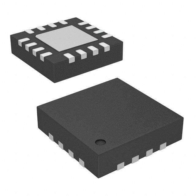
ICGOO在线商城 > 射频/IF 和 RFID > RF 前端(LNA + PA) > CC1190RGVR
- 型号: CC1190RGVR
- 制造商: Texas Instruments
- 库位|库存: xxxx|xxxx
- 要求:
| 数量阶梯 | 香港交货 | 国内含税 |
| +xxxx | $xxxx | ¥xxxx |
查看当月历史价格
查看今年历史价格
CC1190RGVR产品简介:
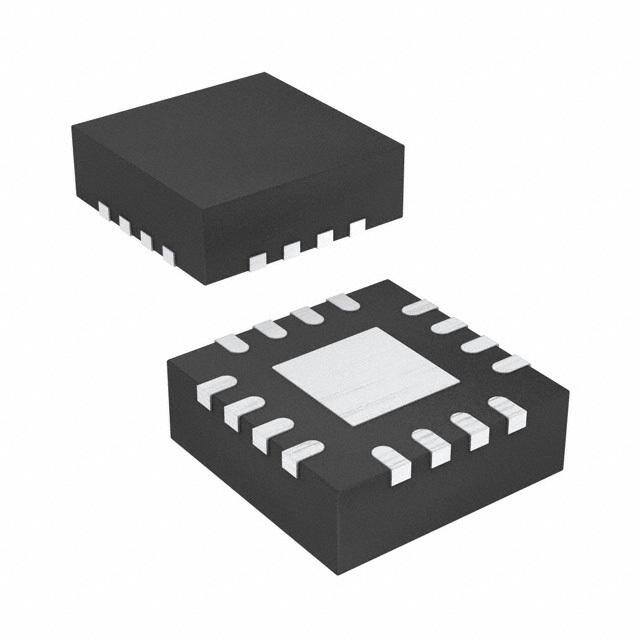
ICGOO电子元器件商城为您提供CC1190RGVR由Texas Instruments设计生产,在icgoo商城现货销售,并且可以通过原厂、代理商等渠道进行代购。 CC1190RGVR价格参考。Texas InstrumentsCC1190RGVR封装/规格:RF 前端(LNA + PA), RF Front End 850MHz ~ 950MHz ISM 16-VQFN (4x4)。您可以下载CC1190RGVR参考资料、Datasheet数据手册功能说明书,资料中有CC1190RGVR 详细功能的应用电路图电压和使用方法及教程。
Texas Instruments(德州仪器)的CC1190RGVR是一款RF前端芯片,集成了低噪声放大器(LNA)和功率放大器(PA),广泛应用于需要高性能无线通信的场景。以下是其主要应用场景:

 1. 远程无线传感器网络
   - CC1190RGVR支持高灵敏度接收和高功率发射,适用于远程无线传感器网络。例如,环境监测系统中的温湿度、气压或空气质量传感器可以通过CC1190RGVR实现长距离数据传输。
   - 在农业领域,用于土壤湿度、作物生长状态等信息的远距离监控。

 2. 智能仪表(水表、电表、气表)
   - 在智能抄表系统中,CC1190RGVR可以增强信号覆盖范围,确保数据从远程仪表到集中器的可靠传输。
   - 支持Sub-1GHz频段,适合穿透能力强的应用场景,如地下管道或建筑物内部的仪表数据采集。

 3. 工业自动化与控制
   - 在工业物联网(IIoT)中,CC1190RGVR可用于无线控制系统,例如工厂设备的状态监控和远程控制。
   - 提供稳定的射频性能,支持复杂的工业环境中多节点通信的需求。

 4. 智能家居设备
   - 用于家庭自动化系统中的无线通信模块,例如智能门锁、安防摄像头、烟雾报警器等。
   - 提高了信号强度和覆盖范围,确保家庭内所有设备的稳定连接。

 5. 医疗健康设备
   - 在远程医疗或可穿戴设备中,CC1190RGVR可用于将患者的生命体征数据(如心率、血压)传输到医院或数据中心。
   - 其低功耗特性延长了电池寿命,适合便携式医疗设备。

 6. 无线报警与安防系统
   - 在火灾报警、入侵检测等安防系统中,CC1190RGVR能够提供可靠的长距离通信能力。
   - 高增益LNA和PA设计确保信号在复杂环境下的稳定性。

 7. 无人机与遥控模型
   - 用于无人机或其他遥控设备的无线通信链路,提高控制距离和抗干扰能力。
   - 支持Sub-1GHz频段的低功耗传输,减少对设备电源的压力。

 总结
CC1190RGVR凭借其高性能的LNA和PA设计,适用于需要长距离、低功耗无线通信的各种场景。它在工业、农业、医疗、智能家居等领域均有广泛应用,能够显著提升系统的通信能力和可靠性。
| 参数 | 数值 |
| 产品目录 | |
| 描述 | IC RF FRONT-END 16VQFN射频前端 850 - 950MHz 射频前端 |
| 产品分类 | RF 前端 (LNA + PA)集成电路 - IC |
| 品牌 | Texas Instruments |
| 产品手册 | |
| 产品图片 |
|
| rohs | 符合RoHS无铅 / 符合限制有害物质指令(RoHS)规范要求 |
| 产品系列 | RF集成电路,射频前端,Texas Instruments CC1190RGVR- |
| 数据手册 | |
| 产品型号 | CC1190RGVR |
| RF类型 | ISM |
| 产品种类 | 射频前端 |
| 供应商器件封装 | 16-VQFN(4x4) |
| 其它名称 | 296-36922-1 |
| 包装 | 剪切带 (CT) |
| 商标 | Texas Instruments |
| 噪声系数 | 2.9 dB |
| 安装风格 | SMD/SMT |
| 封装 | Reel |
| 封装/外壳 | 16-VQFN 裸露焊盘 |
| 封装/箱体 | VQFN-16 |
| 工作电源电压 | 3.7 V |
| 工作频率 | 950 MHz |
| 工厂包装数量 | 2500 |
| 最大工作温度 | + 85 C |
| 最小工作温度 | - 40 C |
| 标准包装 | 1 |
| 特性 | - |
| 类型 | RF Front End |
| 系列 | CC1190 |
| 频率 | 850MHz ~ 950MHz |





- 商务部:美国ITC正式对集成电路等产品启动337调查
- 曝三星4nm工艺存在良率问题 高通将骁龙8 Gen1或转产台积电
- 太阳诱电将投资9.5亿元在常州建新厂生产MLCC 预计2023年完工
- 英特尔发布欧洲新工厂建设计划 深化IDM 2.0 战略
- 台积电先进制程称霸业界 有大客户加持明年业绩稳了
- 达到5530亿美元!SIA预计今年全球半导体销售额将创下新高
- 英特尔拟将自动驾驶子公司Mobileye上市 估值或超500亿美元
- 三星加码芯片和SET,合并消费电子和移动部门,撤换高东真等 CEO
- 三星电子宣布重大人事变动 还合并消费电子和移动部门
- 海关总署:前11个月进口集成电路产品价值2.52万亿元 增长14.8%




PDF Datasheet 数据手册内容提取
CC1190 www.ti.com SWRS089A–NOVEMBER2009–REVISEDFEBRUARY2010 850 – 950 MHz RF Front End CheckforSamples:CC1190 FEATURES APPLICATIONS 1 • SeamlessInterfacetoSub-1GHzLowPower • 850-950MHzISMBandsWirelessSystems RFDevicesfromTexasInstruments • WirelessSensorNetworks • Upto27dBm(0.5W)OutputPower • WirelessIndustrialSystems • 6dBTypicalSensitivityImprovementwith • IEEE802.15.4Systems CC11xxandCC430 • WirelessConsumerSystems • FewExternalComponents • WirelessMetering(AMR/AMI)Systems – IntegratedPA • SmartGridWirelessNetworks – IntegratedLNA DESCRIPTION – IntegratedSwitches CC1190 is a cost-effective and high-performance RF – IntegratedMatchingNetwork Front End for low-power and low-voltage wireless – IntegratedInductors applicationsat850-950MHz. • DigitalControlofLNAandPAGainbyHGM CC1190 is a range extender for the sub-1 GHz Pin low-power RF transceivers, transmitters, and • 50-nAinPowerDown(LNA_EN=PA_EN=0) System-on-ChipdevicesfromTexasInstruments. • HighTransmitPowerEfficiency CC1190 integrates a power amplifier (PA), a – PAE=50%at26dBmOutputPower low-noise amplifier (LNA), switches, and RF matching • LowReceiveCurrentConsumption for the design of a high-performance wireless systems. – 3mAforHighGainMode CC1190 increases the link budget by providing a – 26µAforLowGainMode power amplifier for increased output power, and an • 2.9dBLNANoiseFigure,IncludingSwitchand LNA with low noise figure for improved receiver ExternalAntennaMatch sensitivity. • RoHSCompliant4-mm× 4-mmQFN-16 CC1190 provides an efficient and easy-to-use range Package extender in a compact 4-mm × 4-mm QFN-16 • 2Vto3.7VOperation package. CC1190 BLOCK DIAGRAM VDD_LNA VDD_PA1 VDD_PA2 PA_OUT PA PREAMP PA_IN EN EN TR_SW LNA LNA_OUT EN LNA_IN LOGIC PA_EN LNA_EN BIAS BIAS HGM 1 Pleasebeawarethatanimportantnoticeconcerningavailability,standardwarranty,anduseincriticalapplicationsofTexas Instrumentssemiconductorproductsanddisclaimerstheretoappearsattheendofthisdatasheet. PRODUCTIONDATAinformationiscurrentasofpublicationdate. Copyright©2009–2010,TexasInstrumentsIncorporated Products conform to specifications per the terms of the Texas Instruments standard warranty. Production processing does not necessarilyincludetestingofallparameters.
CC1190 SWRS089A–NOVEMBER2009–REVISEDFEBRUARY2010 www.ti.com Thesedeviceshavelimitedbuilt-inESDprotection.Theleadsshouldbeshortedtogetherorthedeviceplacedinconductivefoam duringstorageorhandlingtopreventelectrostaticdamagetotheMOSgates. ORDERINGINFORMATION DEVICE TEMPERATURE PACKAGE(1) TRANSPORTIONMEDIA CC1190RGVR TapeandReel,2500 -40°Cto85°C QFN(RVG)16 CC1190RGVT TapeandReel,250 (1) Forthemostcurrentpackageandorderinginformation,seethePackageOptionAddendumattheendofthisdocument,orseetheTI websiteatwww.ti.com. ABSOLUTE MAXIMUM RATINGS Undernocircumstancesmusttheabsolutemaximumratingsbeviolated.Stressexceedingoneormoreofthelimitingvalues maycausepermanentdamagetothedevice. VALUE UNIT Supplyvoltage,V Allsupplypinsmusthavethesamevoltage –0.3to3.8 V DD Voltageonanydigitalpin –0.3toVDD+0.3,max3.8 V InputRFlevel 10 dBm Storagetemperaturerange –50to150 °C Human-bodymodel,nonRFpins 2000 V Human-bodymodel,RFpins:PA_IN,PA_OUT,TR_SW, ESD 1500 V LNA_IN,LNA_OUT Chargeddevicemodel 1000 V RECOMMENDED OPERATING CONDITIONS MIN MAX UNIT Ambienttemperaturerange –40 85 °C Operatingsupplyvoltage 2 3.7 V Operatingfrequencyrange 850 950 MHz ELECTRICAL CHARACTERISTICS T =25°C,VDD=3V,f =915MHz(unlessotherwisenoted).MeasuredonCC1190EMreferencedesignincludingexternal C RF matchingcomponentsoptimizedfor915MHzoperation. PARAMETER TESTCONDITIONS MIN TYP MAX UNIT P =-40dBm,HGM=1 3 mA IN Receivecurrent P =-40dBm,HGM=0 26 µA IN P =5dBm,POUT=26.5dBm,HGM=1 302 IN Transmitcurrent Noinputsignal,HGM=1 56 mA Noinputsignal,HGM=0 29 Powerdowncurrent LNA_EN=PA_EN=0 50 200 nA Highinputlevel(controlpins) HGM,LNA_EN,PA_EN 1.3 VDD V Lowinputlevel(controlpins) HGM,LNA_EN,PA_EN 0.3 V Powerdown→Receivemode,switching 300 ns time Powerdown→Transmitmode,switching 600 ns time 2 SubmitDocumentationFeedback Copyright©2009–2010,TexasInstrumentsIncorporated ProductFolderLink(s):CC1190
CC1190 www.ti.com SWRS089A–NOVEMBER2009–REVISEDFEBRUARY2010 ELECTRICAL CHARACTERISTICS (continued) T =25°C,VDD=3V,f =915MHz(unlessotherwisenoted).MeasuredonCC1190EMreferencedesignincludingexternal C RF matchingcomponentsoptimizedfor915MHzoperation. PARAMETER TESTCONDITIONS MIN TYP MAX UNIT RFReceive P =-40dBm,HGM=1 11.6 IN Gain dB P =-40dBm,HGM=0 -6 IN Gainvariationoverfrequency 850–950MHz,P =-40dBm,HGM=1 1.2 dB IN Gainvariationoverpowersupply 2–3.7V,P =-40dBm,HGM=1 1 dB IN HGM=1,includinginternalswitchandexternal 2.9 dB antennamatch Noisefigure HGM=0,includinginternalswitchandexternal 6.2 dBm antennamatch HGM=1 -12.3 Input1dBcompression dBm HGM=0 11.2 InputIP3,HighGainMode HGM=1 -5 dBm Inputreflectioncoefficient,S11,High HGM=1,measuredatantennaport,depends -11.5 dB GainMode onexternalantennaandLNAmatch RFTransmit P =-20dBm,HGM=1 27.9 IN Gain dB P =-20dBm,HGM=0 24.6 IN MaximumOutputPower P =5dBm,HGM=1,VDD=3.7V 27.7 dBm IN P =5dBm,HGM=1 26.5 IN Outputpower,POUT P =0dBm,HGM=1 25.5 dBm IN P =-6dBm,HGM=1 22 IN PowerAddedEfficiency,PAE P =5dBm,HGM=1 48% IN HGM=1 24 Output1dBcompression dBm HGM=0 23.7 Outputpowervariationoverfrequency 850–950MHz,PIN=5dBm,HGM=1 1.7 dB Outputpowervariationoverpowersupply 2V–3.7V,PIN=5dBm,HGM=1 4.5 dB Outputpowervariationovertemperature -40°C–85°C,PIN=5dBm,HGM=1 1 dB 2ndharmonicpower HGM=1,PIN=5dBm 2.5 SeeapplicationnoteAN001(SWRA090)for dBm 3rdharmonicpower regulatoryrequirements. -37 HGM=1,measuredatSMAconnectoron Inputreflectioncoefficient,S11 -10 dB PA_IN/LNA_OUT(TXactive) Copyright©2009–2010,TexasInstrumentsIncorporated SubmitDocumentationFeedback 3 ProductFolderLink(s):CC1190
CC1190 SWRS089A–NOVEMBER2009–REVISEDFEBRUARY2010 www.ti.com DEVICE INFORMATION QFN-16PACKAGE TOPVIEW 1 2 A A A N P P L D_ D_ S D_ D D A D V V BI V 16 15 14 13 GND 1 12 GND PA_OUT 2 11 PA_IN 4x4 QFN-16 GND 3 10 LNA_OUT TR_SW 4 9 GND 5 6 7 8 N M N N LNA_I HG LNA_E PA_E NOTE The exposed die attach pad must be connected to a solid ground plane as this is the primary ground connection for the chip. Inductance in vias to the pad should be minimized. Following the CC1190EM reference layout is recommended. Changes will alter theperformance.AlsoseethePCBlandpatterninformationinthisdatasheet. PINFUNCTIONS PIN I/O DESCRIPTION NO. NAME Theexposeddieattachpadmustbeconnectedtoasolidgroundplane.SeeCC1190EM - GND Ground (SWRR064)referencedesignforrecommendedlayout. 1 GND Ground Secondarygroundconnection.ShouldbeshortedtothedieattachpadonthetopPCBlayer. 2 PA_OUT RF OutputofPA. 3 GND Ground Secondarygroundconnection.ShouldbeshortedtothedieattachpadonthetopPCBlayer. 4 TR_SW RF RXTXswitchpin. 5 LAN_IN RF InputofLNA. Digitalcontrolpin. 6 HGM DigitalInput HGM=1→DeviceinHighGainMode. HGM=0→DeviceinLowGainMode. 7 LNA_EN DigitalInput Digitalcontrolpin.SeeTable2andTable3fordetails. 8 PA_EN DigitalInput Digitalcontrolpin.SeeTable2andTable3fordetails. 9 GND Ground Secondarygroundconnection.ShouldbeshortedtothedieattachpadonthetopPCBlayer. 10 LNA_OUT RF OutputofLNA. 11 PA_IN RF InputofPA. 12 GND Ground Secondarygroundconnection.ShouldbeshortedtothedieattachpadonthetopPCBlayer. 13 VDD_LNA Power 2–3.7VSupplyVoltage. 14 BIAS Analog Biasinginput.Resistorbetweenthisnodeandgroundsetsbiascurrent. 15 VDD_PA2 Power 2–3.7VSupplyVoltage. 16 VDD_PA1 Power 2–3.7VSupplyVoltage. 4 SubmitDocumentationFeedback Copyright©2009–2010,TexasInstrumentsIncorporated ProductFolderLink(s):CC1190
CC1190 www.ti.com SWRS089A–NOVEMBER2009–REVISEDFEBRUARY2010 CC1190EM Evaluation Module VDD VDD SMA L24 L23 CL2211 DD_PA1 DD_PA2 DD_LNA PA_IN C111 SMA PA_OUT V V V C28 C25 C24 L22 LNA_OUT C101 C22 CC1190 TR_SW PA_EN PA_EN C51 LNA_EN LNA_EN LNA_IN HGM HGM S A BI R141 Figure1. CC1190EMEvaluationModule Table1.ListofMaterialsOptimizedfor915MHzOperation (SeetheCC1190EMReferenceDesign,SWRR064) DEVICE FUNCTION VALUE L21 PAloadinductor 10nH,LQW18AN10NG10fromMurata L22 RXTXswitchandLNAmatch 7.5nH,LQW15AN7N5G00fromMurata L23 Partofantennamatch 2.2nH,LQW15AN2N2C10DfromMurata L24 Partofantennamatch 3.9nH,LQW15AN3N9C00fromMurata C21 DCblock 47pF,GRM1555C1H470JZ01DfromMurata C22 RXTXswitchandLNAmatch 12pF,GRM1555C1H120JZ01DfromMurata C24 Partofantennamatch 3.3pF:GRM1555C1H3R3CZ01DfromMurata C25 Partofantennamatch 8.2pF:GRM1555C1H8R2CZ01DfromMurata C28 Partofantennamatch 0.5pF,GRM1555C1HR50CZ01DfromMurata C51 PartofLNAmatch 12pF,GRM1555C1H120JZ01DfromMurata C101 DCblock 47pF:GRM1555C1H470JZ01DfromMurata C111 DCblock 47pF:GRM1555C1H470JZ01DfromMurata R141 Biasresistor 3.3kΩ,RK73H1ETTP3301FfromKoa Copyright©2009–2010,TexasInstrumentsIncorporated SubmitDocumentationFeedback 5 ProductFolderLink(s):CC1190
CC1190 SWRS089A–NOVEMBER2009–REVISEDFEBRUARY2010 www.ti.com TYPICAL CHARACTERISTICS T =25°C,V =3V,f =915MHz(unlessotherwisenoted).MeasuredonCC1190EMreferencedesignincludingexternal C DD RF matchingcomponentsoptimizedfor915MHzoperation. 3.10 11.7 12.5 -5 GAIN -5.2 3.05 11.5 HGM GAIN B B 12.0 -5.4 d d M - 3.00 11.3 M - dB -5.6 dB HG HG n- n - n 2.95 11.1 n ai 11.5 -5.8 ai Figure i 2.90 10.9 AGain i HGM G LGM GAIN -6 LGM G e NF N 11.0 -6.2 s L oi 2.85 10.7 N -6.4 2.80 10.5 10.5 -6.6 850 860 870 880 890 900 910 920 930 940 950 -40 -30 -20 -10 0 10 20 30 40 50 60 70 80 90 Frequency - MHz Temperature -oC Figure2.LNAGainandNoiseFigurevsOperatingFrequency Figure3.LNAGainvsTemperature SPACER 12.0 -5.8 11.9 -5.85 HGM GAIN 11.8 -5.9 B B n- d 11.7 LGM GAIN -5.95 n - d ai 11.6 -6 ai G G HGM 11.5 -6.05 LGM S (1,1) 11.4 -6.1 11.3 -6.15 11.2 -6.2 2 2.2 2.4 2.6 2.8 3 3.2 3.4 3.6 Supply Voltage - V Frequency (850 MHz to 950 MHz) Figure4.LNAGainvsSupplyVoltage Figure5.InputImpedanceofLNAMeasuredfromAntennaPort onCC1190EM(RXActive) 60 400 60 360 50 350 55 340 I_VDD PAE m 40 300 m 50 320 B PAE B - d 30 250 mA - d 45 300 mA E - %, POUT 1200 POUT I_VDD 125000 Current - E - %, POUT 3450 226800 Current - PA 0 100 PA 30 POUT 240 -10 50 25 220 -20 0 20 200 -40 -35 -30 -25 -20 -15 -10 -5 0 5 850 860 870 880 890 900 910 920 930 940 950 Pin - dBm Frequency - MHz Figure6.PAOutputPower,PAEandCurrentConsumption Figure7.PAOutputPower,PAEandCurrentConsumption vsInputPower vsOperatingFrequencyat5dBmInputPower 6 SubmitDocumentationFeedback Copyright©2009–2010,TexasInstrumentsIncorporated ProductFolderLink(s):CC1190
CC1190 www.ti.com SWRS089A–NOVEMBER2009–REVISEDFEBRUARY2010 TYPICAL CHARACTERISTICS (continued) T =25°C,V =3V,f =915MHz(unlessotherwisenoted).MeasuredonCC1190EMreferencedesignincludingexternal C DD RF matchingcomponentsoptimizedfor915MHzoperation. 60 360 55 350 55 340 50 PAE 325 PAE m 50 320 m B B 45 300 - d 45 300 mA - d mA PAE - %, POUT 334500 POUT I_VDD 222468000 Current - PAE - %, POUT 334500 I_VDDPOUT 222257505 Current - 25 220 25 200 20 200 20 175 -40 -30 -20 -10 0 10 20 30 40 50 60 70 80 2 2.2 2.4 2.6 2.8 3 3.2 3.4 3.6 Temperature -oC Supply Voltage - V Figure8.PAOutputPower,PAEandCurrentConsumption Figure9.PAOutputPower,PAEandCurrentConsumption vsTemperatureat5dBmInputPower vsSupplyVoltageat5dBmInputPower 1) 1, S ( Frequency (850 MHz to 950 MHz) Figure10.InputImpedanceMeasuredatSMAconnectoronPA_IN/LNA_OUTonCC1190EM(TXActive) Copyright©2009–2010,TexasInstrumentsIncorporated SubmitDocumentationFeedback 7 ProductFolderLink(s):CC1190
CC1190 SWRS089A–NOVEMBER2009–REVISEDFEBRUARY2010 www.ti.com INTERFACE AND CONTROL Controlling the Output Power from CC1190 The output power of CC1190 is controlled by controlling the input power. The CC1190 PA is designed to work in compression (class AB), and the best efficiency is reached when a strong input signal is applied. The output power can be reduced by setting the pin HGM low. If a reduced maximum output power is wanted, the impedance seen by the PA should be increased, thus increasing the PA efficiency by changing the output matchingnetwork. Input Levels on Control Pins The three digital control pins (PA_EN, LNA_EN, HGM) have built-in level-shifting functionality, meaning that if CC1190isoperatingfroma3.6Vsupplyvoltage,thecontrolpinswillstillsense1.6-1.8Vsignalsaslogical'1'. AnexampleoftheaboveisthatPA_ENisconnecteddirectlytothePA_ENpinonCC110x,buttheglobalsupply voltage is 3.6 V. The PA_EN pin on CC110x will switch between 0 V (RX) and 1.8 V (TX), and this is still a high enoughvoltagetocontroltheoperatingmodeofCC1190. However,theinputvoltagesshouldnothavelogical'1'levelthatishigherthanthesupply. Connecting CC1190 to a CC102X Device Table2.ControlLogicforConnectingCC1190toaCC102XDevice PA_EN LNA_EN HGM ModeOfOperation 0 0 don'tcare PowerDown 0 1 0 RXLowGainMode 0 1 1 RXHighGainMode 1 0 0 TXLowGainMode 1 0 1 TXHighGainMode VDD 1 2 A A A N P P L PA_IN RF_OUT D_ D_ D_ SAW D D D LNA_OUT RF__IN V V V PA_OUT CC102X CC1190 TR_SW PA_EN PA_EN LNA_IN LNA_EN LNA_EN S HGM A BI Connectedto VDD/GND/MCU Figure11. CC1190+CC102XApplicationCircuit 8 SubmitDocumentationFeedback Copyright©2009–2010,TexasInstrumentsIncorporated ProductFolderLink(s):CC1190
CC1190 www.ti.com SWRS089A–NOVEMBER2009–REVISEDFEBRUARY2010 Connecting CC1190 to a CC110X Device Table3.ControlLogicforConnectingCC1190toaCC110XDevice PA_EN LNA_EN HGM ModeOfOperation 0 0 don'tcare PowerDown 0 1 0 RXLowGainMode 0 1 1 RXHighGainMode 1 0 0 TXLowGainMode 1 0 1 TXHighGainMode VDD 1 2 A DD_PA DD_PA DD_LN LNAP_AO_UINT SAW RRFF__PN V V V PA_OUT CC110X CC1190 TR_SW PA_EN PA_EN LNA_IN LNA_EN S A HGM BI Connected to MCU Connected to VDD/GND/MCU Figure12. CC1190+CC110XApplicationCircuit Connecting CC1190 to a CC430 or CC111X Device Table4.ControlLogicforConnectingCC1190toaCC430orCC111XDevice PA_EN LNA_EN HGM ModeOfOperation 0 0 don'tcare PowerDown 0 1 0 RXLowGainMode 0 1 1 RXHighGainMode 1 0 0 TXLowGainMode 1 0 1 TXHighGainMode VDD 1 2 A DD_PA DD_PA DD_LN LNAP_AO_UINT SAW RRFF__PN V V V PA_OUT CC430/CC111X CC1190 TR_SW PA_EN PA_EN LNA_IN LNA_EN LNA_EN S A HGM BI Connected to VDD/GND/SoC Figure13. CC1190+CC430/CC111XApplicationCircuit Copyright©2009–2010,TexasInstrumentsIncorporated SubmitDocumentationFeedback 9 ProductFolderLink(s):CC1190
CC1190 SWRS089A–NOVEMBER2009–REVISEDFEBRUARY2010 www.ti.com REVISION HISTORY ChangesfromOriginal(November2009)toRevisionA Page • ChangedthedatasheetfromProductPreviewtoProduction ............................................................................................. 1 10 SubmitDocumentationFeedback Copyright©2009–2010,TexasInstrumentsIncorporated ProductFolderLink(s):CC1190
PACKAGE OPTION ADDENDUM www.ti.com 17-Jan-2016 PACKAGING INFORMATION Orderable Device Status Package Type Package Pins Package Eco Plan Lead/Ball Finish MSL Peak Temp Op Temp (°C) Device Marking Samples (1) Drawing Qty (2) (6) (3) (4/5) CC1190RGVR ACTIVE VQFN RGV 16 2500 Green (RoHS CU NIPDAU Level-3-260C-168 HR -40 to 85 CC1190 & no Sb/Br) CC1190RGVT ACTIVE VQFN RGV 16 250 Green (RoHS CU NIPDAU Level-3-260C-168 HR -40 to 85 CC1190 & no Sb/Br) (1) The marketing status values are defined as follows: ACTIVE: Product device recommended for new designs. LIFEBUY: TI has announced that the device will be discontinued, and a lifetime-buy period is in effect. NRND: Not recommended for new designs. Device is in production to support existing customers, but TI does not recommend using this part in a new design. PREVIEW: Device has been announced but is not in production. Samples may or may not be available. OBSOLETE: TI has discontinued the production of the device. (2) Eco Plan - The planned eco-friendly classification: Pb-Free (RoHS), Pb-Free (RoHS Exempt), or Green (RoHS & no Sb/Br) - please check http://www.ti.com/productcontent for the latest availability information and additional product content details. TBD: The Pb-Free/Green conversion plan has not been defined. Pb-Free (RoHS): TI's terms "Lead-Free" or "Pb-Free" mean semiconductor products that are compatible with the current RoHS requirements for all 6 substances, including the requirement that lead not exceed 0.1% by weight in homogeneous materials. Where designed to be soldered at high temperatures, TI Pb-Free products are suitable for use in specified lead-free processes. Pb-Free (RoHS Exempt): This component has a RoHS exemption for either 1) lead-based flip-chip solder bumps used between the die and package, or 2) lead-based die adhesive used between the die and leadframe. The component is otherwise considered Pb-Free (RoHS compatible) as defined above. Green (RoHS & no Sb/Br): TI defines "Green" to mean Pb-Free (RoHS compatible), and free of Bromine (Br) and Antimony (Sb) based flame retardants (Br or Sb do not exceed 0.1% by weight in homogeneous material) (3) MSL, Peak Temp. - The Moisture Sensitivity Level rating according to the JEDEC industry standard classifications, and peak solder temperature. (4) There may be additional marking, which relates to the logo, the lot trace code information, or the environmental category on the device. (5) Multiple Device Markings will be inside parentheses. Only one Device Marking contained in parentheses and separated by a "~" will appear on a device. If a line is indented then it is a continuation of the previous line and the two combined represent the entire Device Marking for that device. (6) Lead/Ball Finish - Orderable Devices may have multiple material finish options. Finish options are separated by a vertical ruled line. Lead/Ball Finish values may wrap to two lines if the finish value exceeds the maximum column width. Important Information and Disclaimer:The information provided on this page represents TI's knowledge and belief as of the date that it is provided. TI bases its knowledge and belief on information provided by third parties, and makes no representation or warranty as to the accuracy of such information. Efforts are underway to better integrate information from third parties. TI has taken and continues to take reasonable steps to provide representative and accurate information but may not have conducted destructive testing or chemical analysis on incoming materials and chemicals. TI and TI suppliers consider certain information to be proprietary, and thus CAS numbers and other limited information may not be available for release. Addendum-Page 1
PACKAGE OPTION ADDENDUM www.ti.com 17-Jan-2016 In no event shall TI's liability arising out of such information exceed the total purchase price of the TI part(s) at issue in this document sold by TI to Customer on an annual basis. Addendum-Page 2
None
None
None
IMPORTANTNOTICE TexasInstrumentsIncorporated(TI)reservestherighttomakecorrections,enhancements,improvementsandotherchangestoits semiconductorproductsandservicesperJESD46,latestissue,andtodiscontinueanyproductorserviceperJESD48,latestissue.Buyers shouldobtainthelatestrelevantinformationbeforeplacingordersandshouldverifythatsuchinformationiscurrentandcomplete. TI’spublishedtermsofsaleforsemiconductorproducts(http://www.ti.com/sc/docs/stdterms.htm)applytothesaleofpackagedintegrated circuitproductsthatTIhasqualifiedandreleasedtomarket.AdditionaltermsmayapplytotheuseorsaleofothertypesofTIproductsand services. ReproductionofsignificantportionsofTIinformationinTIdatasheetsispermissibleonlyifreproductioniswithoutalterationandis accompaniedbyallassociatedwarranties,conditions,limitations,andnotices.TIisnotresponsibleorliableforsuchreproduced documentation.Informationofthirdpartiesmaybesubjecttoadditionalrestrictions.ResaleofTIproductsorserviceswithstatements differentfromorbeyondtheparametersstatedbyTIforthatproductorservicevoidsallexpressandanyimpliedwarrantiesforthe associatedTIproductorserviceandisanunfairanddeceptivebusinesspractice.TIisnotresponsibleorliableforanysuchstatements. BuyersandotherswhoaredevelopingsystemsthatincorporateTIproducts(collectively,“Designers”)understandandagreethatDesigners remainresponsibleforusingtheirindependentanalysis,evaluationandjudgmentindesigningtheirapplicationsandthatDesignershave fullandexclusiveresponsibilitytoassurethesafetyofDesigners'applicationsandcomplianceoftheirapplications(andofallTIproducts usedinorforDesigners’applications)withallapplicableregulations,lawsandotherapplicablerequirements.Designerrepresentsthat,with respecttotheirapplications,Designerhasallthenecessaryexpertisetocreateandimplementsafeguardsthat(1)anticipatedangerous consequencesoffailures,(2)monitorfailuresandtheirconsequences,and(3)lessenthelikelihoodoffailuresthatmightcauseharmand takeappropriateactions.DesigneragreesthatpriortousingordistributinganyapplicationsthatincludeTIproducts,Designerwill thoroughlytestsuchapplicationsandthefunctionalityofsuchTIproductsasusedinsuchapplications. TI’sprovisionoftechnical,applicationorotherdesignadvice,qualitycharacterization,reliabilitydataorotherservicesorinformation, including,butnotlimitedto,referencedesignsandmaterialsrelatingtoevaluationmodules,(collectively,“TIResources”)areintendedto assistdesignerswhoaredevelopingapplicationsthatincorporateTIproducts;bydownloading,accessingorusingTIResourcesinany way,Designer(individuallyor,ifDesignerisactingonbehalfofacompany,Designer’scompany)agreestouseanyparticularTIResource solelyforthispurposeandsubjecttothetermsofthisNotice. TI’sprovisionofTIResourcesdoesnotexpandorotherwisealterTI’sapplicablepublishedwarrantiesorwarrantydisclaimersforTI products,andnoadditionalobligationsorliabilitiesarisefromTIprovidingsuchTIResources.TIreservestherighttomakecorrections, enhancements,improvementsandotherchangestoitsTIResources.TIhasnotconductedanytestingotherthanthatspecifically describedinthepublisheddocumentationforaparticularTIResource. Designerisauthorizedtouse,copyandmodifyanyindividualTIResourceonlyinconnectionwiththedevelopmentofapplicationsthat includetheTIproduct(s)identifiedinsuchTIResource.NOOTHERLICENSE,EXPRESSORIMPLIED,BYESTOPPELOROTHERWISE TOANYOTHERTIINTELLECTUALPROPERTYRIGHT,ANDNOLICENSETOANYTECHNOLOGYORINTELLECTUALPROPERTY RIGHTOFTIORANYTHIRDPARTYISGRANTEDHEREIN,includingbutnotlimitedtoanypatentright,copyright,maskworkright,or otherintellectualpropertyrightrelatingtoanycombination,machine,orprocessinwhichTIproductsorservicesareused.Information regardingorreferencingthird-partyproductsorservicesdoesnotconstitutealicensetousesuchproductsorservices,orawarrantyor endorsementthereof.UseofTIResourcesmayrequirealicensefromathirdpartyunderthepatentsorotherintellectualpropertyofthe thirdparty,oralicensefromTIunderthepatentsorotherintellectualpropertyofTI. TIRESOURCESAREPROVIDED“ASIS”ANDWITHALLFAULTS.TIDISCLAIMSALLOTHERWARRANTIESOR REPRESENTATIONS,EXPRESSORIMPLIED,REGARDINGRESOURCESORUSETHEREOF,INCLUDINGBUTNOTLIMITEDTO ACCURACYORCOMPLETENESS,TITLE,ANYEPIDEMICFAILUREWARRANTYANDANYIMPLIEDWARRANTIESOF MERCHANTABILITY,FITNESSFORAPARTICULARPURPOSE,ANDNON-INFRINGEMENTOFANYTHIRDPARTYINTELLECTUAL PROPERTYRIGHTS.TISHALLNOTBELIABLEFORANDSHALLNOTDEFENDORINDEMNIFYDESIGNERAGAINSTANYCLAIM, INCLUDINGBUTNOTLIMITEDTOANYINFRINGEMENTCLAIMTHATRELATESTOORISBASEDONANYCOMBINATIONOF PRODUCTSEVENIFDESCRIBEDINTIRESOURCESOROTHERWISE.INNOEVENTSHALLTIBELIABLEFORANYACTUAL, DIRECT,SPECIAL,COLLATERAL,INDIRECT,PUNITIVE,INCIDENTAL,CONSEQUENTIALOREXEMPLARYDAMAGESIN CONNECTIONWITHORARISINGOUTOFTIRESOURCESORUSETHEREOF,ANDREGARDLESSOFWHETHERTIHASBEEN ADVISEDOFTHEPOSSIBILITYOFSUCHDAMAGES. UnlessTIhasexplicitlydesignatedanindividualproductasmeetingtherequirementsofaparticularindustrystandard(e.g.,ISO/TS16949 andISO26262),TIisnotresponsibleforanyfailuretomeetsuchindustrystandardrequirements. WhereTIspecificallypromotesproductsasfacilitatingfunctionalsafetyorascompliantwithindustryfunctionalsafetystandards,such productsareintendedtohelpenablecustomerstodesignandcreatetheirownapplicationsthatmeetapplicablefunctionalsafetystandards andrequirements.Usingproductsinanapplicationdoesnotbyitselfestablishanysafetyfeaturesintheapplication.Designersmust ensurecompliancewithsafety-relatedrequirementsandstandardsapplicabletotheirapplications.DesignermaynotuseanyTIproductsin life-criticalmedicalequipmentunlessauthorizedofficersofthepartieshaveexecutedaspecialcontractspecificallygoverningsuchuse. Life-criticalmedicalequipmentismedicalequipmentwherefailureofsuchequipmentwouldcauseseriousbodilyinjuryordeath(e.g.,life support,pacemakers,defibrillators,heartpumps,neurostimulators,andimplantables).Suchequipmentincludes,withoutlimitation,all medicaldevicesidentifiedbytheU.S.FoodandDrugAdministrationasClassIIIdevicesandequivalentclassificationsoutsidetheU.S. TImayexpresslydesignatecertainproductsascompletingaparticularqualification(e.g.,Q100,MilitaryGrade,orEnhancedProduct). Designersagreethatithasthenecessaryexpertisetoselecttheproductwiththeappropriatequalificationdesignationfortheirapplications andthatproperproductselectionisatDesigners’ownrisk.Designersaresolelyresponsibleforcompliancewithalllegalandregulatory requirementsinconnectionwithsuchselection. DesignerwillfullyindemnifyTIanditsrepresentativesagainstanydamages,costs,losses,and/orliabilitiesarisingoutofDesigner’snon- compliancewiththetermsandprovisionsofthisNotice. MailingAddress:TexasInstruments,PostOfficeBox655303,Dallas,Texas75265 Copyright©2017,TexasInstrumentsIncorporated
 Datasheet下载
.jpg)
