
 Datasheet下载
- 型号: CB1-R-SM-12V
- 制造商: Panasonic Corporation
- 库位|库存: xxxx|xxxx
- 要求:
| 数量阶梯 | 香港交货 | 国内含税 |
| +xxxx | $xxxx | ¥xxxx |
查看当月历史价格
查看今年历史价格
CB1-R-SM-12V产品简介:
ICGOO电子元器件商城为您提供CB1-R-SM-12V由Panasonic Corporation设计生产,在icgoo商城现货销售,并且可以通过原厂、代理商等渠道进行代购。 CB1-R-SM-12V价格参考。Panasonic CorporationCB1-R-SM-12V封装/规格:汽车继电器, 。您可以下载CB1-R-SM-12V参考资料、Datasheet数据手册功能说明书,资料中有CB1-R-SM-12V 详细功能的应用电路图电压和使用方法及教程。
| 参数 | 数值 |
| 产品目录 | |
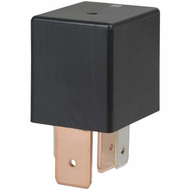
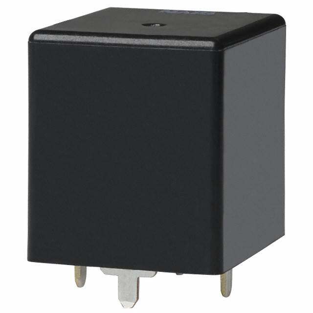
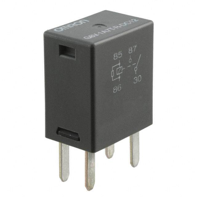
| 描述 | RELAY AUTOMOTIVE SPDT 40A 12V车用继电器 1 Form C, 12VDC with resistor inside |
| 产品分类 | |
| 品牌 | Panasonic Electric Works |
| 产品手册 | |
| 产品图片 |
|
| rohs | 符合RoHS无铅 / 符合限制有害物质指令(RoHS)规范要求 |
| 产品系列 | 车用继电器,Panasonic Industrial Devices CB1-R-SM-12VCB |
| mouser_ship_limit | 该产品可能需要其他文档才能发货到中国。 |
| 数据手册 | |
| 产品型号 | CB1-R-SM-12V |
| 产品目录绘图 |
|
| 产品种类 | 车用继电器 |
| 关闭电压(最小值) | 1.2 VDC |
| 其它名称 | 255-2164 |
| 其它有关文件 | |
| 功耗 | 1.6 W |
| 包装 | 散装 |
| 商标 | Panasonic Industrial Devices |
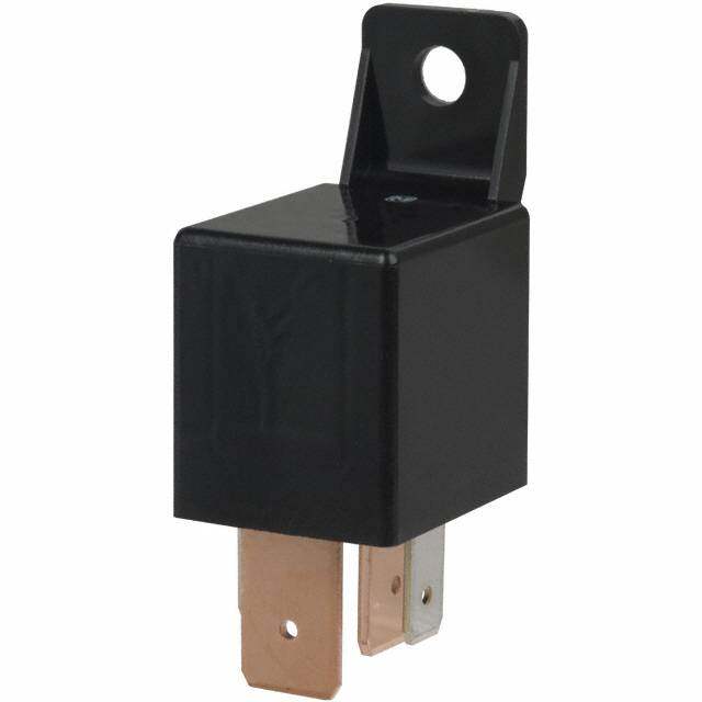
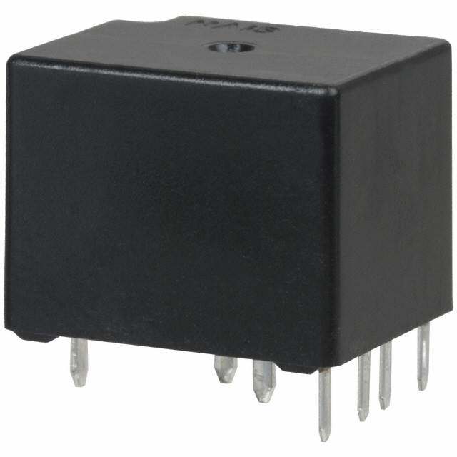
| 安装类型 | 底座安装 |
| 安装风格 | Panel |
| 导通电压(最大值) | 7 VDC |
| 封装 | Bulk |
| 工作时间 | 15ms |
| 工作温度 | -40°C ~ 85°C |
| 工厂包装数量 | 50 |
| 开关电压 | 14VDC -标称 |
| 标准包装 | 50 |
| 特性 | 电阻器,密封 - 完全 |
| 端子类型 | 快速连接 - 0.250"(6.3mm) |
| 类型 | Automotive Relays |
| 线圈功率 | 1.6 W |
| 线圈电压 | 12VDC |
| 线圈电流 | 134mA |
| 线圈电阻 | 89.5 欧姆 |
| 线圈端接 | Clip |
| 线圈类型 | 无锁存 |
| 继电器类型 | 自动 |
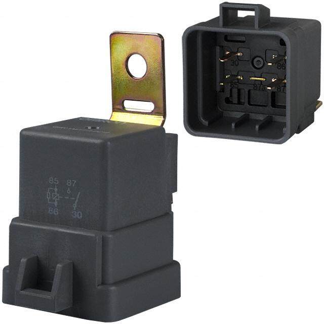
| 触头外形 | SPDT(1 C 型) |
| 触头材料 | 银合金,无镉 |
| 触点形式 | 1 Form C (SPDT-BM) |
| 触点材料 | Silver Alloy |
| 触点端接 | Clip |
| 释放时间 | 15ms |
| 额定接触(电流) | 40A |


- 商务部:美国ITC正式对集成电路等产品启动337调查
- 曝三星4nm工艺存在良率问题 高通将骁龙8 Gen1或转产台积电
- 太阳诱电将投资9.5亿元在常州建新厂生产MLCC 预计2023年完工
- 英特尔发布欧洲新工厂建设计划 深化IDM 2.0 战略
- 台积电先进制程称霸业界 有大客户加持明年业绩稳了
- 达到5530亿美元!SIA预计今年全球半导体销售额将创下新高
- 英特尔拟将自动驾驶子公司Mobileye上市 估值或超500亿美元
- 三星加码芯片和SET,合并消费电子和移动部门,撤换高东真等 CEO
- 三星电子宣布重大人事变动 还合并消费电子和移动部门
- 海关总署:前11个月进口集成电路产品价值2.52万亿元 增长14.8%
PDF Datasheet 数据手册内容提取
CB MINI-ISO CB RELAYS AUTOMOTIVE RELAY FEATURES TYPICAL APPLICATIONS • This relay has an Mini-ISO • Automobiles (International Organization for Headlights, Cell motors, Air conditioners, Standardization) terminal ABS, EPS, etc. arrangement. • Construction equipment • Relay is compact and high capacity • Agricultural equipment, Conveyor, (40 A). etc. Compact form factor realized with space saving 22 26 mm .866 1.024 inch small base area thanks to integrated bobbin and base construction. Features high switching capacity of 40 A • Features high thermal resistance of 125C 257F (heat resistant type). Heat resistant type is available that can withstand use near engines. (40 A switching capacity) • Built-in resistor type is also available. ORDERING INFORMATION CB Contact arrangement 1a:1 Form A 1: 1 Form C Contact rating Nil:Standard type H: High contact capacity type Protective construction Nil:Sealed type F: Flux-resistant type Heat resistant of types Nil:Standard type T: Heat resistant type Protective element Nil:None R: with resistor inside Mounting classification Nil:Plug-in type P: PC board type M: Bracket type Coil voltage (DC) 12V, 24 V ds_61202_en_cb: 010113J 1
CB TYPES 1. Standard type Sealed type Flux-resistant type Contact arrangement Mounting classification Nominal coil voltage Part No. Part No. 12V DC CB1a-P-12V CB1aF-P-12V PC board type 24V DC CB1a-P-24V CB1aF-P-24V 12V DC CB1a-12V CB1aF-12V 1 Form A Plug-in type 24V DC CB1a-24V CB1aF-24V 12V DC CB1a-M-12V CB1aF-M-12V Bracket type 24V DC CB1a-M-24V CB1aF-M-24V 12V DC CB1-P-12V CB1F-P-12V PC board type 24V DC CB1-P-24V CB1F-P-24V 12V DC CB1-12V CB1F-12V 1 Form C Plug-in type 24V DC CB1-24V CB1F-24V 12V DC CB1-M-12V CB1F-M-12V Bracket type 24V DC CB1-M-24V CB1F-M-24V 12V DC CB1aH-P-12V CB1aHF-P-12V PC board type* 24V DC CB1aH-P-24V CB1aHF-P-24V High contact capacity 12V DC CB1aH-12V CB1aHF-12V Plug-in type (1 Form A) 24V DC CB1aH-24V CB1aHF-24V 12V DC CB1aH-M-12V CB1aHF-M-12V Bracket type 24V DC CB1aH-M-24V CB1aHF-M-24V Standard packing; Carton: 50 pcs. Case: 200 pcs. Note:Please use “CBR” to order with resistor inside type. (Asterisks “” should be filled in from ORDERING INFORMATION.) 2. Heat resistant type Sealed type Flux-resistant type Contact arrangement Mounting classification Nominal coil voltage Part No. Part No. 12V DC CB1a-T-P-12V CB1aF-T-P-12V PC board type 24V DC CB1a-T-P-24V CB1aF-T-P-24V 12V DC CB1a-T-12V CB1aF-T-12V 1 Form A Plug-in type 24V DC CB1a-T-24V CB1aF-T-24V 12V DC CB1a-T-M-12V CB1aF-T-M-12V Bracket type 24V DC CB1a-T-M-24V CB1aF-T-M-24V 12V DC CB1-T-P-12V CB1F-T-P-12V PC board type 24V DC CB1-T-P-24V CB1F-T-P-24V 12V DC CB1-T-12V CB1F-T-12V 1 Form C Plug-in type 24V DC CB1-T-24V CB1F-T-24V 12V DC CB1-T-M-12V CB1F-T-M-12V Bracket type 24V DC CB1-T-M-24V CB1F-T-M-24V 12V DC CB1aH-T-P-12V CB1aHF-T-P-12V PC board type* 24V DC CB1aH-T-P-24V CB1aHF-T-P-24V High contact capacity 12V DC CB1aH-T-12V CB1aHF-T-12V Plug-in type (1 Form A) 24V DC CB1aH-T-24V CB1aHF-T-24V 12V DC CB1aH-T-M-12V CB1aHF-T-M-12V Bracket type 24V DC CB1aH-T-M-24V CB1aHF-T-M-24V Standard packing; Carton: 50 pcs. Case: 200 pcs. Note:Please use “CBR” to order with resistor inside type. (Asterisks “” should be filled in from ORDERING INFORMATION.) RATING 1. Coil data 1) No protective element Contact Nominal coil Nominal operating Nominal operating Usable voltage Pick-up voltage Drop-out voltage Coil resistance arrangement voltage current power range 1FormA, 12V DC 3 to 7V DC 1.2 to 4.2V DC 117mA 103 1.4W 10 to 16V DC 1FormC 24V DC 6 to 14V DC 2.4 to 8.4V DC 75mA 320 1.8W 20 to 32V DC 117mA 103 1.4W (PC board type) High contact 12V DC 3 to 7V DC 1.2 to 4.2V DC 150mA 80 1.8W 10 to 16V DC capacity (1 Form A) 24V DC 6 to 14V DC 2.4 to 8.4V DC 58mA 411 1.4W (PC board type) 20 to 32V DC 75mA 320 1.8W Note:Other pick-up voltage types are also available. Please contact us for details. 2) With resistor inside Nominal operating Combined resistance Nominal operating Contact Nominal coil Pick-up voltage Drop-out voltage Usable voltage current (10%) power arrangement voltage (Initial, at 20C 68F) (Initial, at 20C 68F) range (at 20C 68F) (at 20C 68F) (at 20C 68F) 1FormA, 12V DC 3 to 7V DC 1.2 to 4.2V DC 134mA 89.5 1.6W 10 to 16V DC 1FormC 24V DC 6 to 14V DC 2.4 to 8.4V DC 84mA 287.2 2.0W 20 to 32V DC 2 ds_61202_en_cb: 010113J
CB 2. Specifications 1) Standard type (12 V coil voltage) Characteristics Item Specification High contact capacity Arrangement 1 Form A 1 Form C (1 Form A) Contact Contact resistance (Initial) Typ2m (By voltage drop 6 V DC 1 A) Contact material Ag alloy (Cadmium free) N.O.: 40A 14V DC 70A 14V DC (at 20C 68F) Nominal switching capacity (Initial) 40A 14V DC N.C.: 30A 14V DC 50A 14V DC (at 85C 185F) Max. carrying current (Initial) Rating (14V DC, at 85C 185F, continuous) N.O.: 40A N.O.: 40A, N.C.: 30A N.O.: 40A Nominal operating power 1.4W 1.4W 1.8W (1.4W: PC board type) Min. switching capacity (resistive load)*1 1A 14V DC Insulation resistance (Initial) Min. 20 M (at 500V DC, Measurement at same location as “Breakdown voltage” section.) Breakdown Between open contacts 500 Vrms for 1 min. (Detection current: 10mA) voltage (Initial) Between contacts and coil 500 Vrms for 1 min. (Detection current: 10mA) Electrical characteristics Operate time (at nominal coil voltage) Max. 15ms (excluding contact bounce time) (Initial) (at 20C 68F) Release time (at nominal coil voltage) Max. 15ms (excluding contact bounce time) (Initial) (at 20C 68F) Functional Min. 200 m/s2 {20G} Shock resistance Mechanical Destructive Min. 1,000 m/s2 {100G} characteristics Vibration Functional 10 Hz to 500 Hz, Min. 44.1m/s2 {4.5G} resistance Destructive 10 Hz to 2,000 Hz, Min. 44.1m/s2 {4.5G} Time of vibration for each direction; X. Y. Z direction: 4 hours Electrical (at nominal switching capacity) Flux-resistant type: Min. 105, Sealed type: Min. 5104 (Operating frequency: 2s ON, 2s OFF) Expected life Mechanical Min. 106 (at 120 cpm) Standard type; Ambient temperature: –40 to +85C –40 to +185F, Conditions for operation, transport and Humidity: 5 to 85% R.H. (Not freezing and condensing at low temperature) Conditions storage*2 Heat resistant type; Ambient temperature: –40 to +125C –40 to +257F, Humidity: 5 to 85% R.H. (Not freezing and condensing at low temperature) Max. operating speed 15 cpm (at nominal switching capacity) Mass Approx. 33 g 1.16 oz Notes: *1. This value can change due to the switching frequency, environmental conditions, and desired reliability level, therefore it is recommended to check this with the actual load. *2. The upper operation ambient temperature limit is the maximum temperature that can satisfy the coil temperature rise value. Refer to “6. Usage, Storage and Transport Conditions“ in AMBIENT ENVIRONMENT section in Relay Technical Information. 2) Standard type (24 V coil voltage) Characteristics Item Specifications High contact capacity Arrangement 1 Form A 1 Form C (1 Form A) Contact Contact resistance (Initial) Max. 15m (By voltage drop 6 V DC 1 A) Contact material Ag alloy (Cadmium free) N.O.: 20A 28V DC Nominal switching capacity (Initial) 20A 28V DC 20A 28V DC N.C.: 10A 28V DC Rating Max. carrying current (Initial) 20A N.O.: 20A, N.C.: 10A 20A (28V DC, at 85C 185F, continuous) Nominal operating power 1.8W 1.8W 1.8W, 1.4W (PC board type) Note:All other specifications are the same as those of standard type (12 V coil voltage) 3) Heat resistant type (12 V and 24 V coil voltage) Specifications Characteristics Item 12V 24V High contact High contact Arrangement 1 Form A 1 Form C capacity 1 Form A 1 Form C capacity Contact (1 Form A) (1 Form A) Contact resistance (Initial) Max. 15m (By voltage drop 6 V DC 1 A) Contact material Ag alloy (Cadmium free) Nominal switching capacity N.O.: 40A 14V DC N.O.: 20A 28V DC 40A 14V DC 40A 14V DC 20A 28V DC 20A 28V DC (Initial) N.C.: 30A 14V DC N.C.: 10A 28V DC Max. carrying current (Initial) N.O.: 50A 14V DC 45A 50A N.O.: 25A 28V DC 50A 14V DC 25A 28V DC 25A 28V DC (at 85C 185F, continuous)* N.C.: 30A 14V DC 14V DC 14V DC N.C.: 10A 28V DC Rating 1.4W 1.8W, (PC Nominal operating power 1.4W 1.4W 1.8W 1.8W 1.8W 1.4W board (PC board type) type) Notes:1.All other specifications are the same as those of standard type (12 V coil voltage) 2.*Current value in which carry current is possible when the coil temperature is 180C 356F ds_61202_en_cb: 010113J 3
CB REFERENCE DATA CB RELAYS (Standard type) 1. Allowable ambient temperature 2. Max. switching capability (Resistive load) 3. Ambient temperature and operating voltage (Heat resistant standard type) (Standard type) range (Standard type) °mum allowable ambient temperature, C1111024568000000 342000AAA Switching voltage, VDC 5432600000 (N.O. side Room temperature) Coil applied voltage, VDC 133224550500 Operating voltage range Maxi 40 105 cycle line 10 10 5 Actual value Pick-up voltage 20 (Max. 105 cycle) (Cold start) 90 100 110 120 130 140 150 0 0 0 10 20 30 40 50 –40–20 0 20 40 60 8085100120 Applied coil voltage, %V Switching current, A Ambient temperature, °C Assumption: • Maximum mean coil temperature: 180C • Curves are based on 1.4W (Nominal power consumption of the unsupprressed coil at nominal voltage) 4. Distribution of pick-up and drop-out voltage 5. Distribution of operate and release time Sample: CB1-P-12V, 42pcs. Sample: CB1-P-12V, 42pcs. 60 60 Pick-up voltage Operate time Drop-out voltage Release time 50 50 n n ntity, 40 ntity, 40 a a Qu 30 Qu 30 20 20 10 10 0 0 1.5 2.0 2.5 3.0 3.5 4.0 4.5 5.0 5.5 6.0 1.01.52.02.53.03.54.04.55.05.56.06.57.0 Voltage, V Operate and release time, ms 6. Electrical life test (Motor free) Change of pick-up and drop-out voltage Change of contact resistance Sample: CB1F-12V, 5pcs. Load: 25A 14V DC, motor free actual load 6 50 Operating frequency: ON 1s, OFF 9s V ACmircbuieintt temperature: Room temTRpeeeslarteayd thu sararenmepslse k-up and drop-out voltage, 2453 PDircokp--uopu vt ovlotaltgaege MMMMXXaaiinnxx.... ΩContact resistance, m 24003 c Pi 10 14V DC M Motor 1 Max. X 00 5 10 00 5 10Min. No. of operations, x 104 No. of operations, x 104 Observation of load waveform with current probe and digital oscilloscope Load current waveform Inrush current: 80A, Steady current: 25A 20A 200ms 4 ds_61202_en_cb: 010113J
CB CB RELAYS (High contact capacity type) 1. Allowable ambient temperature 2. Ambient temperature and operating voltage 3. Distribution of pick-up and drop-out voltage (High resistant/high contact capacity type) range Sample: CB1aHF-12V, 53pcs. (High contact capacity/standard type) °mperature, C111245000 VDC 3450 6700 PDircokp--uopu vt ovlotaltgaege mum allowable ambient te1068000 345000AAA Coil applied voltage, 13225050 Operating voltage range Quantity, n 32450000 Maxi 40 60A 10 10 5 70A Pick-up voltage 2090 100 110 120 130 140 150 0−40−20 0 20(Co4ld0 sta6r0t) 8085100120 00 0.51.01.52.02.53.03.54.04.55.05.56.06.5 Applied coil voltage, %V Ambient temperature, °C Voltage, V Assumption: • Maximum mean coil temperature: 180C • Curves are based on 1.4W (Nominal power consumption of the unsupprressed coil at nominal voltage) 4. Distribution of operate and release time 5. Contact resistance Sample: CB1aHF-12V, 53pcs. Sample: CB1aHF-12V, 53pcs. (By voltage drop 6V DC 1A) 12 70 e, ms 10 Operate time 60 m nd release ti 68 Quantity, n 4500 e a 30 perat 4 20 O Release time 2 10 0 0 8 10 12 14 1.01.2 1.4 1.6 1.8 2.0 2.2 2.4 2.6 2.8 Coil voltage, V Resistance, mΩ 6. Electrical life test (Motor free) Change of pick-up and drop-out voltage Change of contact resistance Sample: CB1aH-12V, 3pcs. Load: Inrush current: 64A/Steady current: 35A 10 50 Fan motor actual load (motor free) 12V DC V Operating frequency: ON 3s, OFF 7s e, 9 g Ω ACmircbuieintt3 tsemperature: Ro7osm temperature k-up and drop-out volta 468753 DPircokp--uopu tv ovoltaltaggee MMXainx.. Contact resistance, m 234000 10s Pic 2 MXax. 10 Max. Min. X 1 Min. 0 0 0 5 10 0 5 10 No. of operations, x 104 No. of operations, x 104 M Load current waveform Inrush current: 64A, Steady current: 35A 10A 500ms ds_61202_en_cb: 010113J 5
CB DIMENSIONS (mm inch) Download CCAADD DDaattaa from our Web site. 1. PC board type External dimensions Schematic (Bottom view) CAD Data 1 Form A 86 25.0 .984 30 87 85 4.5 .177 Including resistor type also available 1.0 2.15 22.0 .039 6.3 .085 .866 1 Form C .248 26.0 1.024 86 87a 30 87 85 86 87a .383.41 Including resistor type also available 16.8 0.8 30 .661 .031 85 87 PC board pattern (Bottom view) 8 2.6 .83.145 .102 4(or5)x2.6 17.9.331 4(or5)x.102 1 Form C type only .705 86 8.4 87a .331 16.8 .661 30 87 Dimension: General tolerance 44((oorr55))xx1.0.455 85 Max. 1mm .039 inch: 0.1 .004 8.0 1 Form C type only .315 1 to 3mm .039 to .118 inch: 0.2 .008 8.4 Min. 3mm .118 inch: 0.3 .012 .331 17.9 .705 Tolerance: 0.1 .004 2. Plug-in type CAD Data External dimensions Schematic (Bottom view) 1 Form A 86 25.0 .984 30 87 85 11.0.145.07 Including resistor type also available .433 1.7 dia. 5x6.3 22.0 1 Form C .067 dia. 5x.248 .866 86 26.0 87a 1.024 30 8.3.341 85 87 86 87a Including resistor type also available 16.8 .003.81 3085 87 .661 8 2.6 .315 .102 8.4 .331 17.9 .705 Dimension: General tolerance Max. 1mm .039 inch: 0.1 .004 1 to 3mm .039 to .118 inch: 0.2 .008 Min. 3mm .118 inch: 0.3 .012 6 ds_61202_en_cb: 010113J
CB 3. Bracket type CAD Data External dimensions Schematic (Bottom view) 4.0±0.1 1 Form A 16.0 .157±.004 5..241±30±.1.0 d0i4a. .630 .10.677 3086 .62.306.1663.00 85 87 Including resistor type also available 25.0 1 Form C .984 86 87a 30 4.0 .1413.30.157 85 87 22.0 5x6.3 Including resistor type also available .866 5x.248 26.0 1.024 0.8 .031 30 85 86 87a* 1.770.95 8 8.4 .315 87 .331 8.4 .120.62 1.666.81 .331 Dimension: General tolerance Max. 1mm .039 inch: 0.1 .004 1 to 3mm .039 to .118 inch: 0.2 .008 Min. 3mm .118 inch: 0.3 .012 4. High contact capacity type (1 Form A) (Plug-in type) CAD Data External dimensions Schematic (Bottom view) 86 30 25.5 1.004 85 87 Including resistor type also available 15.0 .41.507 1.413.03 .591 5.8 .228 2x6.3±0.08 2x9.5±0.08 26.5 2x.248±.003 22.0 2x.374±.003 1.043 .866 4x1.7 dia. hole 4x.067 dia. hole 8.4 0.8 .331 .031 86 1.2 16.8 .047 .661 30 85 87 8.4 2.6 .331 .102 17.9 .705 Dimension: General tolerance Max. 1mm .039 inch: 0.1 .004 1 to 3mm .039 to .118 inch: 0.2 .008 Min. 3mm .118 inch: 0.3 .012 ds_61202_en_cb: 010113J 7
CB 5. High contact capacity type (1 Form A) (PC board type) CAD Data External dimensions Schematic (Bottom view) 86 30 12.50.05.4013.09 .10.34.019.757 .10.309 85 87 5.3 5.3 4.5 Including resistor type also available .209 .209 .177 33xx1.0.677 9.5 6.3 22xx2.0.1855 A* 9.5 33xx1.0.767 PC board pattern (Bottom view) .374 .248 .374 12.60.453 2.826.06 .015.45 .120.26 33xx.20.8155 Sealed by epoxy resin 8.4 2x0.8 .331 86 8.4 22xx1.0.231 86 3.1.954 16.8 3x3.x017.18 30 87 .370.87.331.1666.18 2x.047 30 3.1.954 .661 85 85 87 3¥2.15 3x1.8 3x.085 3x.071 7.8 8.4 8.4 .307 .331 3.9 3.9 .331 17.9 .154.15417.9 2.6 .705 .705 .102 Tolerance: 0.1 .004 * Intervals between terminals is measured at A surface level. Dimension: General tolerance Max. 1mm .039 inch: 0.1 .004 1 to 3mm .039 to .118 inch: 0.2 .008 Min. 3mm .118 inch: 0.3 .012 NOTES 1. Soldering 2. Usage, transport and storage Max. 350C 662F (solder temperature), conditions within 3 seconds (soldering time) 1) Ambient temperature, humidity, and The effect on the relay depends on the atmospheric pressure during usage, actual PC board used. Please verify the transport, and storage of the relay: PC board to be used. (1) Temperature: –40 to +85C –40 to +185F (Standard type) –40 to +125C –40 to +257F (High heat- resistant type) (2) Humidity: 2 to 85% RH (Avoid freezing and condensation.) (3) Atmospheric pressure: 86 to 106 kPa The humidity range varies with the temperature. Use within the range indicated in the graph below. (Temperature and humidity range for usage, transport, and storage) Humidity, %RH 85 Tolerance range (Avoid freezing (Avoid when used at condensation temperatures when used at lower than temperatures 0°C32°F) 52 h0i°gChe3r2 t°hFa)n –40 0 85 110125 –40 +32 +185 +230+257 Temperature, °C°F For Cautions for Use, see Relay Technical Information. 8 ds_61202_en_cb: 010113J