ICGOO在线商城 > 开发板,套件,编程器 > 评估板 - LED 驱动器 > CAT3649AGEVB

 Datasheet下载
- 型号: CAT3649AGEVB
- 制造商: ON Semiconductor
- 库位|库存: xxxx|xxxx
- 要求:
| 数量阶梯 | 香港交货 | 国内含税 |
| +xxxx | $xxxx | ¥xxxx |
查看当月历史价格
查看今年历史价格
CAT3649AGEVB产品简介:
ICGOO电子元器件商城为您提供CAT3649AGEVB由ON Semiconductor设计生产,在icgoo商城现货销售,并且可以通过原厂、代理商等渠道进行代购。 CAT3649AGEVB价格参考。ON SemiconductorCAT3649AGEVB封装/规格:评估板 - LED 驱动器, CAT3649 QUAD-Mode® Series 6, Non-Isolated Output LED Driver Evaluation Board。您可以下载CAT3649AGEVB参考资料、Datasheet数据手册功能说明书,资料中有CAT3649AGEVB 详细功能的应用电路图电压和使用方法及教程。
| 参数 | 数值 |
| 产品目录 | 编程器,开发系统半导体 |
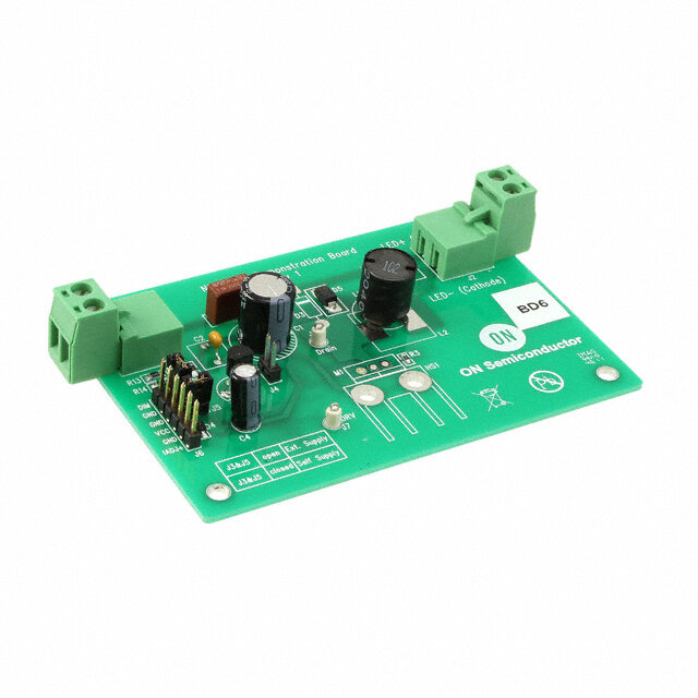
| 描述 | BOARD EVALUATION FOR CAT3649电源管理IC开发工具 EVB FOR CAT3649 |
| 产品分类 | |
| 品牌 | ON Semiconductor |
| 产品手册 | http://www.onsemi.com/PowerSolutions/evalBoard.do?id=CAT3649AGEVB |
| 产品图片 |
|
| rohs | 符合RoHS无铅 / 符合限制有害物质指令(RoHS)规范要求 |
| 产品系列 | 电源管理IC开发工具,ON Semiconductor CAT3649AGEVBQUAD-Mode® |
| 数据手册 | |
| 产品型号 | CAT3649AGEVB |
| 产品 | Evaluation Boards |
| 产品种类 | 电源管理IC开发工具 |
| 使用的IC/零件 | CAT3649 |
| 其它名称 | CAT3649AGEVBOS |
| 商标 | ON Semiconductor |
| 工具用于评估 | CAT3649A |
| 所含物品 | 板 |
| 接口类型 | USB |
| 标准包装 | 1 |
| 特性 | 亮度控制 |
| 电压-输入 | 3.3V,5V |
| 电压-输出 | - |
| 电流-输出/通道 | 25mA |
| 类型 | Charge Pumps |
| 设计资源 | |
| 输出和类型 | 6,非隔离 |
| 输出电流 | 25 mA |


- 商务部:美国ITC正式对集成电路等产品启动337调查
- 曝三星4nm工艺存在良率问题 高通将骁龙8 Gen1或转产台积电
- 太阳诱电将投资9.5亿元在常州建新厂生产MLCC 预计2023年完工
- 英特尔发布欧洲新工厂建设计划 深化IDM 2.0 战略
- 台积电先进制程称霸业界 有大客户加持明年业绩稳了
- 达到5530亿美元!SIA预计今年全球半导体销售额将创下新高
- 英特尔拟将自动驾驶子公司Mobileye上市 估值或超500亿美元
- 三星加码芯片和SET,合并消费电子和移动部门,撤换高东真等 CEO
- 三星电子宣布重大人事变动 还合并消费电子和移动部门
- 海关总署:前11个月进口集成电路产品价值2.52万亿元 增长14.8%

PDF Datasheet 数据手册内容提取
CAT3649AGEVB CAT3649 Evaluation Board User's Manual Introduction http://onsemi.com This document describes the CAT3649 evaluation board for the ON Semiconductor CAT3649 6−Channel EVAL BOARD USER’S MANUAL Quad−Mode LED Driver with an Ambient Light Sensor circuit, NOA1211, that can control the LEDs intensity Board Hardware proportionally with the ambient light intensity. The evaluation board contains one CAT3649 in an The functionality and major parameters of the CAT3649 application circuit driving a total of six LEDs and one can be evaluated with the CAT3649 evaluation board. NOA1211. The Ambient Light Sensor is connected to the A detailed description and electrical characteristics are LED driver via the C8051F321 microcontroller, which is available in the CAT3649 and NOA1211 datasheets. illustrated in Figure 2. Figure 1. CAT3649 Evaluation Board Figure 2. Ambient Light Sensor Mode Block Diagram © Semiconductor Components Industries, LLC, 2012 1 Publication Order Number: November, 2012 − Rev. 1 EVBUM2164/D
CAT3649AGEVB Figure 3. CAT3649AGEVB Board Schematic Table 1. BILL OF MATERIALS* Substi- Desig- Toler- Manufacturer Part tution nator Qty Description Value ance Footprint Manufacturer Number Allowed U1 1 6 Channel LED Driver - - TQFN16 ON CAT3649HV3-GT2 No Semiconductor U2 1 Ambient Light Sensor - - 3 x 3 mm ON NOA1211 No Semiconductor U3 1 8 bit Microcontroller - - CUDFN Silicon C8051F321 Yes Laboratories U4 1 Low Dropout Regulator (5 V to 3.3 V) - 1.6 x 1.6 ON CAT6218-330TDG No Semiconductor U5 1 5 V Voltage Regulator - - MLP-28 ON MC78M05ABDT No Semiconductor D1 to D6 6 White LED - - SOT-223 Lite-On LTW-150TK Yes D7 1 Red LED - - DPAK-3 Everlight EL17-215SURC Yes C1 to C4, 8 Ceramic Capacitor 1 (cid:2)F / 10 V, 10% 1206 Kemet C0805C105K9RACTU Yes C6, C8, X7R C11, C13 C7, C9, 5 Ceramic Capacitor 100 nF 10% 0805 AVX 0805ZC104KAT2A Yes C10, C16, C14 C5 1 Ceramic Capacitor 47 nF 10% 0805 AVX 08053C473KAT2A Yes C15 1 Tantalum Capacitor 10 (cid:2)F/10V 10% 0805 Vishay TM8R106K010UBA Yes *All products listed are Pb−free. http://onsemi.com 2
CAT3649AGEVB Table 1. BILL OF MATERIALS* Substi- Desig- Toler- Manufacturer Part tution nator Qty Description Value ance Footprint Manufacturer Number Allowed R1 1 SMD Resistor 1/8 W, 100 k(cid:3) 1% 0805 Vishay RL0805K100-1 Yes R2 1 SMD Resistor 1/8 W, 4.7 k(cid:3) 1% 1210 Vishay RL0805K004.7-1 Yes R3 1 SMD Resistor 1/8 W, 180 (cid:3) 1% 0805 Vishay RL0805K180-1 Yes R4, R5 2 SMD Resistor 1/8 W, 22 k(cid:3) 1% 0805 Vishay RL0805K022-1 Yes R6 1 SMD Resistor 1/8 W, 100 k(cid:3) 1% 0805 Vishay RL0805K100-1 Yes R7 1 SMD Resistor 1/8 W, 200 (cid:3) 1% 0805 Vishay RL0805E200-1 Yes R10 1 SMD Resistor 1/8 W, 0.5 (cid:3) 1% 0805 Yageo RL0805FR-070R5L Yes J1 to J6, 10 3-pin Header Connector, - - 1.54 mm x MMM 2303-6211TG Yes J8 to J11 0.1”, Single Strip 4.62 mm J7 1 2-pin Header Connector, - - 1.54 mm x MMM 2302-6211TG Yes 0.1”, Single Strip 3.08 mm ISP 1 5-pin Header Connector, - - 1.54 mm x MMM 2305-6211TG Yes 0.1”, Single Strip 7.70 mm T1 – T8 8 Pin Receptacle (Test - - 1.54 mm x Mil-Max Various Yes Points) 1.54 mm K1 1 Slide Switch, SPDT - - 11.60 mm x E-Switch EG1218 Yes 4.00 mm SW1, 2 Pushbutton - - 3.50 mm x Schukat DTS31N Yes SW2 6.00 mm BTH 1 Battery Holder 9 V - - 53.90 mm x Keystone 1294K-ND Yes 29.60 mm *All products listed are Pb−free. Operating Procedure The EN/DIS pushbutton allows the user to enable or to The CAT3649EVAL board can be configured in two shutdown the CAT3649 device. operating modes: stand−alone or PC−controlled. The DIM pushbutton allows the user to program the LED In both operating modes, the supply source for the VIN current in 32 discrete values. On each press on this rail is selected by the jumper J10 to be either 5 V or 3.3 V. pushbutton, the “ADIM” input receives a 50 (cid:2)s pulse. On Table2 shows the configurations for jumper J10 to set the the rising edge of the pulse, the LED current is decreased by VIN voltage. 3.2% from full scale. The user can obtain the same effect by continuously Table 2. VIN SELECTION holding the DIM pushbutton down. For each 0.4 second J10 VIN interval, the “ADIM” input of the device will receive a pulse. 1 − 2 5 V PC Controlled 2 − 3 3.3 V The CAT3649 EVAL board is equipped with a 8−bit microcontroller and can be connected to the PC via USB Stand−alone interface using a USB A/B type cable. This cable can be In this configuration, only the “Analog dimming” obtained from a local electronics supply store. function can be tested. The jumper J11 must be set in (1−2) position for USB The Ambient Light Sensor (ALS) is disabled in this mode. power operation. The jumper J11 must be set in (2−3) position for The jumpers J8 and J9 must be set to (2−3) position to for stand−alone operation power. control of EN/DIS, ADIM, and PWM via USB. The jumpers J8 and J9 must be set to (2−3) position to use In this mode, the board is powered from the USB onboard pushbuttons EN/DIS and ADIM. interface. The evaluation board can be powered either from an The GUI commands are described in the section on−board 9 V supply (9 V alkaline battery) or from an “Graphical User Interface (GUI)”. external supply applied between VBAT and GND test points (located on the bottom side of the board, near the pins for the battery holder). http://onsemi.com 3
CAT3649AGEVB Graphical User Interface (GUI) If the option button “Select” of the frame of the Ambient After connecting the CAT3649 EVAL board to the PC via Light Sensor is pressed while in PWM mode, the “Gain” USB cable, the user can run the program frame will be enabled. CAT3649EVAL.exe. In this frame only the “Power Down” option is selected, If the program is started without the USB connection, the because the “Ambient Light Sensor”, at this moment, is off. following message is displayed: “The CAT3649EVAL (Figure9). Board is not detected!”. The user can select one of the options “Medium” or “Low” The CAT3649 operating mode is selected by pressing one corresponding at the LED’s intensity level domain. of the “check” buttons “PWM” or “ADIM”. (Figure10). Depending of the light’s intensity exposed to the sensor, the LEDs will light proportionally. PWM Operation Mode Operating mechanism is as follows: At start−up, on the GUI is selected, automatically, the The sensor outputs a current proportional to the ambient PWM mode of operation (as shown on Figure 4). light. This current is converted to an output voltage by In this mode, the user can increase/decrease the LEDs resistor R6. The output voltage is applied to the input of the intensity by moving the potentiometer cursor or by pressing 10−bit ADC (Analog to Digital Convertor) from the the keys “−>” and “<−” on the keyboard after selection of the microcontroller. potentiometer. The microcontroller converts the digital value, received Now, in the frame “CAT3649 Command Mode”, the from ADC, into a PWM signal applied to the CAT3649 LED PWM Timing Diagram for a frequency of 300 Hz is Driver. displayed. The period of a pulse (3.3 ms) is the sum between CAT3649 controls the six LEDs’ intensity. “Ton” and “Toff”. Status Box ADIM Operation Mode This box displays various messages about the application After pressing the “ADIM” button, the “ADIM” frame status. becomes enabled (Figure 5). In the “CAT3649 Command Mode” frame, the Timing Diagram is only a line that represents the low level on the ADIM input. If the “EN/DIS” button is pressed, the device will be enabled. The red LEDs on the GUI and on the board will light. The Timing Diagram represents, now, the high level on the ADIM input. (Figure 6). At this moment, the LEDs intensity is at full scale. If the “DIM” button is pressed for a short time a single pulse is applied to the “ADIM” input of the device. If the “DIM” button is pressed continuously, at every 0.4 seconds, a pulse is applied to the device. (Figure 7). If the “EN/DIS” button is pressed again, the device will be disabled. The red LEDs on the GUI and on the board will be off. At this moment, on the ADIM input is at the low level. (Figure8). The LEDs intensity is zero. Ambient Light Sensor NOA1211 Operation Mode Figure 4. GUI – PWM Mode The Ambient Light Sensor NOA1211 can command the LEDs intensity using the microcontroller and the CAT3649. http://onsemi.com 4
CAT3649AGEVB Figure 5. GUI – ADIM Mode Figure 6. GUI – ADIM Mode, Device Enabled Figure 7. GUI – Pulses on ADIM Input Figure 8. GUI – ADIM Shutdown Command Figure 9. GUI – NOA1211 Selection Figure 10. GUI – NOA1211 Power On http://onsemi.com 5
CAT3649AGEVB TEST PROCEDURE FOR THE CAT3649AGEVB EVALUATION BOARD 1.Set the switch K1 in “OFF” position. 13.On the GUI, select the CAT3649 ADIM and then, 2.Verify that shunts are installed on jumpers J1 to J6 “EN/DIS” button. On the board the red LED and in the top position. the white LEDs will light. 3.Verify that a shunt is installed on jumper J7. 14.On the GUI, select the “DIM” button. On the 4.Set a jumper shunt on the header-pin connector board, the LEDs light intensity will decrease. At J11 in (1,2) position. each selection of the “DIM” button, the LEDs light 5.Set a jumper shunt on the header-pin connector J8 intensity will decrease. in (2,3) position. 15.On the GUI, select the “EN/DIS” button. On the 6.Set a jumper shunt on the header-pin connector J9 board the red LED and the white LEDs will not in (2,3) position. light. 7.Set a jumper shunt on the header-pin connector 16.Push the “EXIT” button on the GUI. J10 in (1,2) position. 17.Disconnect the USB interface cable from PC and 8.Connect the “CAT3649EVAL” board to the PC “CAT3649 EVAL” board. through a USB serial interface cable. 18.Insert a 9V battery in the battery holder. 9.Run the program “CAT3649 EVAL.exe”. On the 19.Set a jumper shunt on the header-pin connector PC’s screen appears the CAT3649EVAL GUI. The J11 in (2,3) position. “CAT3649 EVAL” board will be powered up. 20.On the board, set the switch K1 in “ON” position. 10.On the GUI, move the potentiometer cursor. On 21.On the board, push the “EN/DIS” button. The red the board, the light intensity of the LEDs will LED and the white LEDs will light. change proportionally. 22.On the board, push the “DIM” button. the LEDs 11.On the GUI, select the “Ambient Light Sensor” light intensity will decrease. At each selection of frame and then, the “Medium Gain” button. On the the “DIM” button, the LEDs light intensity will board, the light intensity of the LEDs will change decrease. proportionally with the ambient light. 23.On the board, push the “EN/DIS” button. The red 12.On the GUI, unselect the “Ambient Light Sensor” LED and the white LEDs will not light. frame. 24.On the board, set the switch K1 in “OFF” position. http://onsemi.com 6
ON Semiconductor and the ON Semiconductor logo are trademarks of Semiconductor Components Industries, LLC dba ON Semiconductor or its subsidiaries in the United States and/or other countries. ON Semiconductor owns the rights to a number of patents, trademarks, copyrights, trade secrets, and other intellectual property. A listing of ON Semiconductor’s product/patent coverage may be accessed at www.onsemi.com/site/pdf/Patent−Marking.pdf. ON Semiconductor is an Equal Opportunity/Affirmative Action Employer. This literature is subject to all applicable copyright laws and is not for resale in any manner. The evaluation board/kit (research and development board/kit) (hereinafter the “board”) is not a finished product and is as such not available for sale to consumers. The board is only intended for research, development, demonstration and evaluation purposes and should as such only be used in laboratory/development areas by persons with an engineering/technical training and familiar with the risks associated with handling electrical/mechanical components, systems and subsystems. This person assumes full responsibility/liability for proper and safe handling. Any other use, resale or redistribution for any other purpose is strictly prohibited. The board is delivered “AS IS” and without warranty of any kind including, but not limited to, that the board is production−worthy, that the functions contained in the board will meet your requirements, or that the operation of the board will be uninterrupted or error free. ONSemiconductor expressly disclaims all warranties, express, implied or otherwise, including without limitation, warranties of fitness for a particular purpose and non−infringement of intellectual property rights. ONSemiconductor reserves the right to make changes without further notice to any board. You are responsible for determining whether the board will be suitable for your intended use or application or will achieve your intended results. Prior to using or distributing any systems that have been evaluated, designed or tested using the board, you agree to test and validate your design to confirm the functionality for your application. Any technical, applications or design information or advice, quality characterization, reliability data or other services provided by ONSemiconductor shall not constitute any representation or warranty by ONSemiconductor, and no additional obligations or liabilities shall arise from ONSemiconductor having provided such information or services. The boards are not designed, intended, or authorized for use in life support systems, or any FDA Class 3 medical devices or medical devices with a similar or equivalent classification in a foreign jurisdiction, or any devices intended for implantation in the human body. Should you purchase or use the board for any such unintended or unauthorized application, you shall indemnify and hold ONSemiconductor and its officers, employees, subsidiaries, affiliates, and distributors harmless against all claims, costs, damages, and expenses, and reasonable attorney fees arising out of, directly or indirectly, any claim of personal injury or death associated with such unintended or unauthorized use, even if such claim alleges that ONSemiconductor was negligent regarding the design or manufacture of the board. This evaluation board/kit does not fall within the scope of the European Union directives regarding electromagnetic compatibility, restricted substances (RoHS), recycling (WEEE), FCC, CE or UL, and may not meet the technical requirements of these or other related directives. FCC WARNING – This evaluation board/kit is intended for use for engineering development, demonstration, or evaluation purposes only and is not considered by ONSemiconductor to be a finished end product fit for general consumer use. It may generate, use, or radiate radio frequency energy and has not been tested for compliance with the limits of computing devices pursuant to part 15 of FCC rules, which are designed to provide reasonable protection against radio frequency interference. Operation of this equipment may cause interference with radio communications, in which case the user shall be responsible, at its expense, to take whatever measures may be required to correct this interference. ONSemiconductor does not convey any license under its patent rights nor the rights of others. LIMITATIONS OF LIABILITY: ONSemiconductor shall not be liable for any special, consequential, incidental, indirect or punitive damages, including, but not limited to the costs of requalification, delay, loss of profits or goodwill, arising out of or in connection with the board, even if ONSemiconductor is advised of the possibility of such damages. In no event shall ONSemiconductor’s aggregate liability from any obligation arising out of or in connection with the board, under any theory of liability, exceed the purchase price paid for the board, if any. For more information and documentation, please visit www.onsemi.com. PUBLICATION ORDERING INFORMATION LITERATURE FULFILLMENT: TECHNICAL SUPPORT Email Requests to: orderlit@onsemi.com North American Technical Support: Europe, Middle East and Africa Technical Support: Voice Mail: 1 800−282−9855 Toll Free USA/Canada Phone: 00421 33 790 2910 ON Semiconductor Website: www.onsemi.com Phone: 011 421 33 790 2910 For additional information, please contact your local Sales Representative ◊ www.onsemi.com 1