ICGOO在线商城 > 分立半导体产品 > 二极管 - 整流器 - 阵列 > C4D40120D
- 型号: C4D40120D
- 制造商: Cree
- 库位|库存: xxxx|xxxx
- 要求:
| 数量阶梯 | 香港交货 | 国内含税 |
| +xxxx | $xxxx | ¥xxxx |
查看当月历史价格
查看今年历史价格
C4D40120D产品简介:
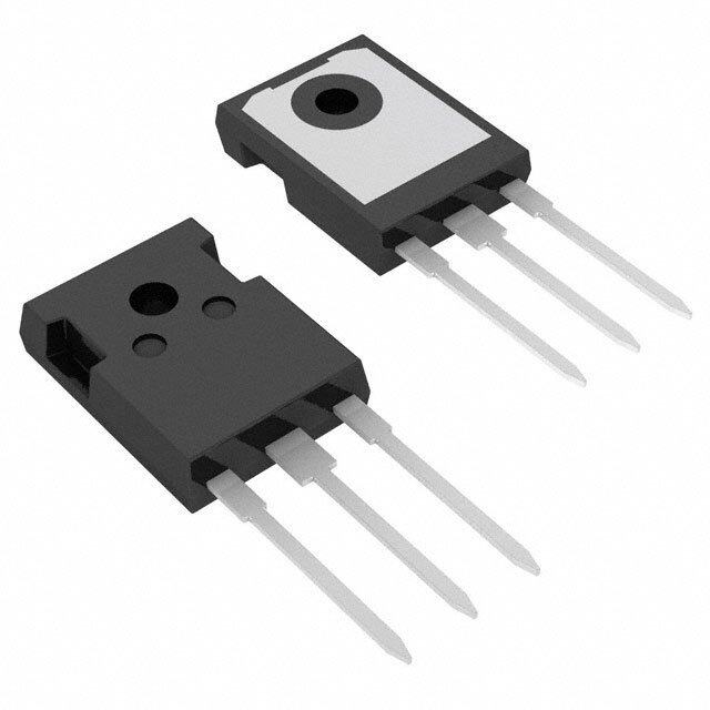
ICGOO电子元器件商城为您提供C4D40120D由Cree设计生产,在icgoo商城现货销售,并且可以通过原厂、代理商等渠道进行代购。 C4D40120D价格参考¥190.37-¥190.37。CreeC4D40120D封装/规格:二极管 - 整流器 - 阵列, Diode Array 1 Pair Common Cathode Silicon Carbide Schottky 1200V 27A Through Hole TO-247-3。您可以下载C4D40120D参考资料、Datasheet数据手册功能说明书,资料中有C4D40120D 详细功能的应用电路图电压和使用方法及教程。
Cree/Wolfspeed的C4D40120D是一款高性能的碳化硅(SiC)二极管整流器阵列,广泛应用于高功率密度和高效能要求的电力电子系统中。该器件具有低正向电压降、快速恢复时间和高耐压特性,使其在多种应用场景中表现出色。

 1. 太阳能逆变器
   C4D40120D常用于太阳能逆变器中,尤其是在直流-交流(DC-AC)转换部分。其高效的整流性能可以减少能量损耗,提高系统的整体效率。由于碳化硅材料的特性,该器件能够在高温环境下稳定工作,延长了系统的使用寿命,并且减少了维护成本。

 2. 电动汽车(EV)充电站
   在电动汽车充电站中,C4D40120D被用于直流快速充电桩的核心电路中。它能够承受高电压和大电流,确保充电过程的安全性和稳定性。此外,其快速恢复时间有助于提高充电效率,缩短充电时间,满足用户对快速充电的需求。

 3. 工业电机驱动
   工业电机驱动系统需要高效、可靠的整流器来将交流电转换为直流电。C4D40120D凭借其低损耗和高可靠性,特别适合应用于高频开关电源和变频器中。它可以有效减少谐波失真,提高电机的运行效率,并降低能耗。

 4. 不间断电源(UPS)
   在不间断电源系统中,C4D40120D用于电池充电和放电管理电路中。其高耐压特性和快速响应能力使得UPS系统能够在市电中断时迅速切换到备用电源,确保负载设备的持续供电。同时,该器件的高效整流功能也有助于延长电池寿命。

 5. 通信基站电源
   通信基站通常位于偏远地区,对电源系统的可靠性和效率有较高要求。C4D40120D可用于基站电源中的整流模块,提供稳定的直流输出。其宽温度范围的工作能力和抗电磁干扰特性,确保了基站电源在恶劣环境下的稳定运行。

总之,C4D40120D凭借其优异的电气性能和可靠性,适用于多种高功率密度和高效能需求的应用场景,特别是在新能源、电动汽车、工业自动化等领域展现出显著的优势。
| 参数 | 数值 |
| 产品目录 | |
| 描述 | DIODE SCHOTTKY 1200V 27A TO247肖特基二极管与整流器 SIC SCHOTTKY DIODE 1200V, 2x20A |
| 产品分类 | 二极管,整流器 - 阵列分离式半导体 |
| 品牌 | Cree, Inc. |
| 产品手册 | |
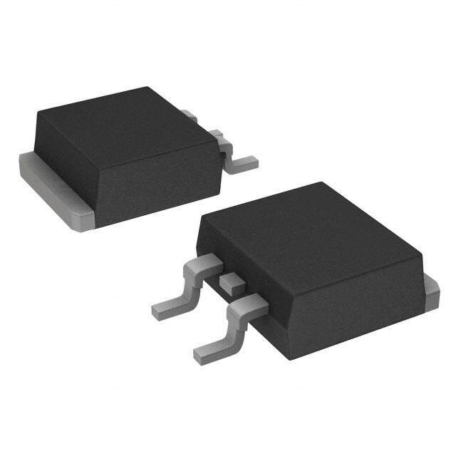
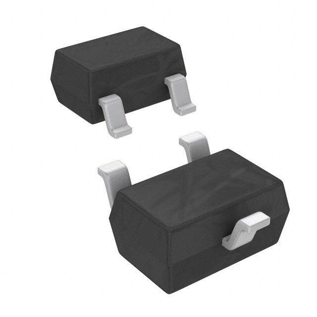
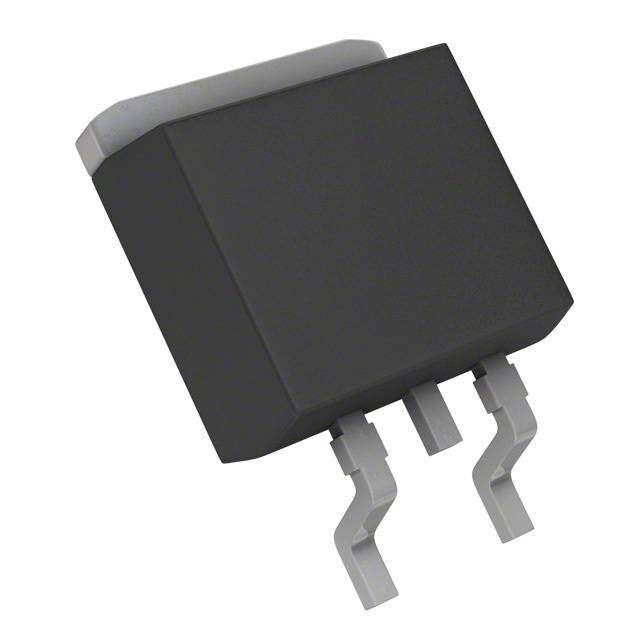
| 产品图片 |
|
| rohs | 符合RoHS无铅 / 符合限制有害物质指令(RoHS)规范要求 |
| 产品系列 | 二极管与整流器,肖特基二极管与整流器,Cree, Inc. C4D40120DZ-Rec™ |
| 数据手册 | |
| 产品型号 | C4D40120D |
| 不同If时的电压-正向(Vf) | 1.8V @ 20A |
| 不同 Vr时的电流-反向漏电流 | 200µA @ 1200V |
| 二极管类型 | 碳化硅肖特基 |
| 二极管配置 | 1 对共阴极 |
| 产品 | Schottky Silicon Carbide Diodes |
| 产品种类 | 肖特基二极管与整流器 |
| 供应商器件封装 | TO-247-3 |
| 包装 | 管件 |
| 反向恢复时间(trr) | 0ns |
| 商标 | Cree, Inc. |
| 安装类型 | 通孔 |
| 安装风格 | Through Hole |
| 封装/外壳 | TO-247-3 |
| 封装/箱体 | TO-247-3 |
| 峰值反向电压 | 1.2 kV |
| 工作温度范围 | - 55 C to + 175 C |
| 工厂包装数量 | 30 |
| 恢复时间 | - |
| 技术 | SiC |
| 最大二极管电容 | 1500 pF |
| 最大功率耗散 | 532 W |
| 最大反向漏泄电流 | 200 uA |
| 最大工作温度 | + 175 C |
| 最大浪涌电流 | 130 A |
| 最小工作温度 | - 55 C |
| 标准包装 | 30 |
| 正向电压下降 | 1.8 V |
| 正向连续电流 | 40 A |
| 热阻 | 0.68°C/W Jc |
| 电压-DC反向(Vr)(最大值) | 1200V(1.2kV) |
| 电流-平均整流(Io)(每二极管) | 27A |
| 速度 | 无恢复时间 > 500mA(Io) |
| 配置 | Dual |



- 商务部:美国ITC正式对集成电路等产品启动337调查
- 曝三星4nm工艺存在良率问题 高通将骁龙8 Gen1或转产台积电
- 太阳诱电将投资9.5亿元在常州建新厂生产MLCC 预计2023年完工
- 英特尔发布欧洲新工厂建设计划 深化IDM 2.0 战略
- 台积电先进制程称霸业界 有大客户加持明年业绩稳了
- 达到5530亿美元!SIA预计今年全球半导体销售额将创下新高
- 英特尔拟将自动驾驶子公司Mobileye上市 估值或超500亿美元
- 三星加码芯片和SET,合并消费电子和移动部门,撤换高东真等 CEO
- 三星电子宣布重大人事变动 还合并消费电子和移动部门
- 海关总署:前11个月进口集成电路产品价值2.52万亿元 增长14.8%



PDF Datasheet 数据手册内容提取
C4D40120D V = 1200 V Silicon Carbide Schottky Diode RRM I (T=135˚C) = 54A** Z-Rec® Rectifier F C Q = 198nC** c Features Package • 1.2kV Schottky Rectifier • Zero Reverse Recovery Current • High-Frequency Operation • Temperature-Independent Switching • Extremely Fast Switching Benefits TO-247-3 • Replace Bipolar with Unipolar Rectifiers • Essentially No Switching Losses • Higher Efficiency • Reduction of Heat Sink Requirements • Parallel Devices Without Thermal Runaway Applications Part Number Package Marking • Switch Mode Power Supplies (SMPS) • Boost diodes in PFC or DC/DC stages • Free Wheeling Diodes in Inverter stages C4D40120D TO-247-3 C4D40120 • AC/DC converters Maximum Ratings (T =25°C unless otherwise specified) C Symbol Parameter Value Unit Test Conditions Note V Repetitive Peak Reverse Voltage 1200 V RRM V Surge Peak Reverse Voltage 1300 V RSM V DC Peak Reverse Voltage 1200 V R 56.5/113 T=25˚C Continuous Forward Current C I 27/54 A T=135˚C Fig. 3 F (Per Leg/Device) C 20/40 T=150˚C C 91* T=25˚C, t=10 ms, Half Sine Pulse I Repetitive Peak Forward Surge Current A C P FRM 61* T=110˚C, t=10 ms, Half Sine Pulse C P 130* T=25˚C, t=10 ms, Half Sine Pulse I Non-Repetitive Forward Surge Current A C P Fig. 8 FSM 110* T=110˚C, t=10 ms, Half Sine Pulse C P 1150* T=25˚C, t=10 ms, Pulse I Non-Repetitive Peak Forward Current A C P Fig. 8 F,Max 950* T=110˚C, t=10 ms, Pulse C P 266/532 T=25˚C P Power Dissipation (Per Leg/Device) W C Fig. 4 tot 114/228 T=110˚C C dV/dt Diode dV/dt ruggedness 200 V/ns V =0-960V R 84.5* T=25˚C, t=10 ms ∫i2dt i2t value A2s C P 60.5* T=110˚C, t=10 ms C P -55 to T Operating Junction Range ˚C J +175 -55 to T Storage Temperature Range ˚C stg +135 1 Nm M3 Screw TO-247 Mounting Torque 8.8 lbf-in 6-32 Screw * Per Leg, ** Per Device 1 C4D40120D Rev. G, 09-2016
Electrical Characteristics (Per Leg) Symbol Parameter Typ. Max. Unit Test Conditions Note 1.5 1.8 I = 20 A T=25°C V Forward Voltage V F J Fig. 1 F 2.2 3 I = 20 A T=175°C F J 35 200 V = 1200 V T=25°C I Reverse Current μA R J Fig. 2 R 65 400 V = 1200 V T=175°C R J V = 800 V, I = 20A R F Q Total Capacitive Charge 99 nC di/dt = 200 A/μs Fig. 5 C T = 25°C J 1500 V = 0 V, T = 25°C, f = 1 MHz R J C Total Capacitance 93 pF V = 400 V, T = 25˚C, f = 1 MHz Fig. 6 R J 67 V = 800 V, T = 25˚C, f = 1 MHz R J E Capacitance Stored Energy 28 μJ V = 800 V Fig. 7 C R Note: This is a majority carrier diode, so there is no reverse recovery charge. Thermal Characteristics Symbol Parameter Typ. Unit Note 0.29** R Thermal Resistance from Junction to Case °C/W Fig. 9 θJC 0.57* * Per Leg, ** Per Device Typical Performance (Per Leg) 40 1 35 TTTJJ=== -275555°°°CCC 0.9 TJ =125°C 0.8 J 30 T =175°C J 0.7 25 0.6 ) ) A A m ( 20 0.5 ( IF R I 0.4 15 0.3 TJ=-55°C 10 TTJ== 2755°°CC 0.2 TJJ =125°C T =175°C J 5 0.1 0 0 0 1 2 3 4 0 500 1000 1500 V (V) V (V) F R Figure 1. Forward Characteristics Figure 2. Reverse Characteristics 2 C4D40120D Rev. G, 09-2016
Typical Performance (Per Leg) 200 300.0 180 250.0 160 10% Duty 20% Duty 140 30% Duty 50% Duty 200.0 70% Duty ) 120 DC A ) ( W eak) 100 (ot 150.0 p T ( P IF 8800 100.0 60 40 50.0 20 0 0.0 25 50 75 100 125 150 175 25 50 75 100 125 150 175 T ˚C T ˚C C C Figure 3. Current Derating Figure 4. Power Derating 140 1600 120 1400 1200 100 1000 C) 80 F) (n (p 800 Q c 60 C 600 40 400 20 200 0 0 0 200 400 600 800 1000 1200 0.1 1 10 100 1000 V (V) V (V) R R Figure 5. Recovery Charge vs. Reverse Voltage Figure 6. Capacitance vs. Reverse Voltage 3 C4D40120D Rev. G, 09-2016
Typical Performance 550.00 1100000000 445.50 440.00 J)J)335.50 uu 11000000 y (y ( J)nergnerg330.00 A)A) mE(citive Ecitive EC225.50 I(FSMI (FSM papa220.00 CaECaC115.50 110000 TTJJ__iinniittiiaall == 2151°0C°C 110.00 5.50 0.00 1100 00 220000 440000 660000 880000 11000000 11.EE-0-505 1E1.-E0-044 1E1.-E0-033 1E1-.0E-202 V Reverse Voltage (V) tp(s) R V (V) t (s) R p Figure 7. Typical Capacitance Stored Energy, per leg Figure 8. Non-Repetitive Peak Forward Surge Current versus Pulse Duration (sinusoidal waveform), per leg W) 0.5 C/W)100E-3 o (/ 0.3 ZZ˚CthJC e, e, e ( 0.1 cc nnc aan dda 10E-3 0.05 eet pps mmi s 0.02 e Ie IRe asas 0.01 SinglePulse CCal o o m n Tn Tr 1E-3 ooe ctictiTh nn uu JJ 100E-6 1E-6 10E-6 100E-6 1E-3 10E-3 100E-3 1 Time, t (s) T (Spec) Figure 9. Device Transient Thermal Impedance 4 C4D40120D Rev. G, 09-2016
Package Dimensions PACKAGE DWG NO. 98WHP03165A Inches Millimeters PackagAe TSOE-24A7dv-anc3ed POS SEenmgiincoenerdiuncgtoWreihai, Inc. OUTLINE ISSUE O Min Max Min Max DATE Sep.05, 2016 A .190 .205 4.83 5.21 A1 .090 .100 2.29 2.54 A2 .075 .085 1.91 2.16 b .042 .052 1.07 1.33 b1 .075 .095 1.91 2.41 b3 .113 .133 2.87 3.38 c .022 .027 0.55 0.68 D .819 .831 20.80 21.10 D1 .640 .695 16.25 17.65 D2 .037 .049 0.95 1.25 E .620 .635 15.75 16.13 E1 .516 .557 13.10 14.15 E2 .145 .201 3.68 5.10 E3 .039 .075 1.00 1.90 E4 .487 .529 12.38 13.43 e e .214 BSC 5.44 BSC L .780 .800 19.81 20.32 L1 .161 .173 4.10 4.40 N 3 ØP .138 .144 3.51 3.65 Q .216 .236 5.49 6.00 NOTE ; 1. ALL METAL SURFACES: TIN PLATED,EXCEPT AREA OF CUT S .238 .248 6.04 6.30 2. DIMENSIONING & TOLERANCEING CONFIRM TO ASME Y14.5M-1994. 3. ALL DIMENSIONS ARE IN MILLIMETERS. T 17.5° REF ANGLES ARE IN DEGREES. 4. THIS DRAWING WILL MEET ALL DIMENSIONS REQUIREMENT OF JEDEC outlines TO-247 AD. W 3.5° REF 1 - GATE X 4° REF 2 - DRAIN (COLLECTOR) 3 - SOURCE (EMITTER) 4 - DRAIN (COLLECTOR) TITLE: COMPANY ASEWeihai TO-2473LD, Only For Cree SHEET 1 OF 3 Recommended Solder Pad Layout Part Number Package Marking C4D40120D TO-247-3 C4D40120 all units are in inches TO-247-3 Note: Recommended soldering profiles can be found in the applications note here: http://www.wolfspeed.com/power_app_notes/soldering 5 C4D40120D Rev. G, 09-2016
Diode Model Diode Model CSD04060 V fV == V V+ +IfI*fR*R TfT T T T T VVTT == 0 .096.95 7++ (T(Tj *J* - 1-.13*.4100-3*)1 0-3) RRTT == 0 .009.06 2+3 (+Tj( *T 1J*.0 62*.1701-3*) 10-4) Note: T = Diode Junction Temperature In Degrees Celsius, j valid from 25°C to 175°C V R T T Notes • RoHS Compliance The levels of RoHS restricted materials in this product are below the maximum concentration values (also referred to as the threshold limits) permitted for such substances, or are used in an exempted application, in accordance with EU Directive 2011/65/EC (RoHS2), as implemented January 2, 2013. RoHS Declarations for this product can be obtained from your Wolfspeed representative or from the Product Ecology section of our website at http:// www.wolfspeed.com/power/tools-and-support/product-ecology. • REACh Compliance REACh substances of high concern (SVHCs) information is available for this product. Since the European Chemi- cal Agency (ECHA) has published notice of their intent to frequently revise the SVHC listing for the foreseeable future,please contact a Cree representative to insure you get the most up-to-date REACh SVHC Declaration. REACh banned substance information (REACh Article 67) is also available upon request. • This product has not been designed or tested for use in, and is not intended for use in, applications implanted into the human body nor in applications in which failure of the product could lead to death, personal injury or property damage, including but not limited to equipment used in the operation of nuclear facilities, life-support machines, cardiac defibrillators or similar emergency medical equipment, aircraft navigation or communication or control systems, or air traffic control systems. Related Links • Cree SiC Schottky diode portfolio: http://www.wolfspeed.com/Power/Products#SiCSchottkyDiodes • Schottky diode Spice models: http://www.wolfspeed.com/power/tools-and-support/DIODE-model-request2 • SiC MOSFET and diode reference designs: http://go.pardot.com/l/101562/2015-07-31/349i Copyright © 2016 Cree, Inc. All rights reserved. Cree, Inc. 4600 Silicon Drive The information in this document is subject to change without notice. Durham, NC 27703 USA Tel: +1.919.313.5300 Cree, the Cree logo, and Zero Recovery are registered trademarks of Cree, Inc. Fax: +1.919.313.5451 www.cree.com/power 66 C4D40120D Rev. G, 09-2016
Mouser Electronics Authorized Distributor Click to View Pricing, Inventory, Delivery & Lifecycle Information: C ree, Inc.: C4D40120D
/C4D40120D.jpg)
 Datasheet下载
