ICGOO在线商城 > C18CF151J-7ZN-X1B
- 型号: C18CF151J-7ZN-X1B
- 制造商: Dielectric Laboratories
- 库位|库存: xxxx|xxxx
- 要求:
| 数量阶梯 | 香港交货 | 国内含税 |
| +xxxx | $xxxx | ¥xxxx |
查看当月历史价格
查看今年历史价格
C18CF151J-7ZN-X1B产品简介:
ICGOO电子元器件商城为您提供C18CF151J-7ZN-X1B由Dielectric Laboratories设计生产,在icgoo商城现货销售,并且可以通过原厂、代理商等渠道进行代购。 提供C18CF151J-7ZN-X1B价格参考以及Dielectric LaboratoriesC18CF151J-7ZN-X1B封装/规格参数等产品信息。 你可以下载C18CF151J-7ZN-X1B参考资料、Datasheet数据手册功能说明书, 资料中有C18CF151J-7ZN-X1B详细功能的应用电路图电压和使用方法及教程。
| 参数 | 数值 |
| 品牌 | Dielectric Laboratories |
| 产品目录 | 无源元件 |
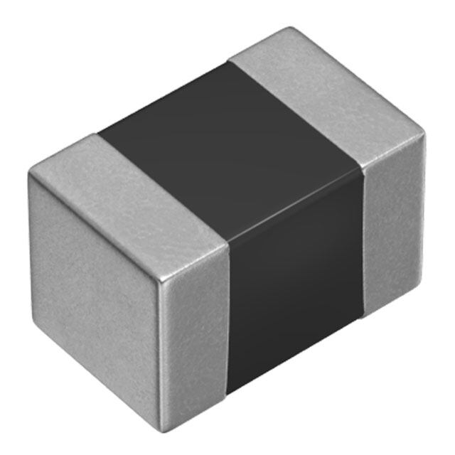
| 描述 | 多层陶瓷电容器MLCC - SMD/SMT 1KV 150 pF +/- 5% 1111 case Matte Tin |
| 产品分类 | |
| 产品手册 | |
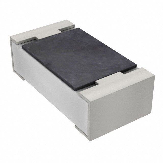
| 产品图片 |
|
| rohs | 符合RoHS |
| 产品系列 | MLCC,多层陶瓷电容器MLCC - SMD/SMT,Dielectric Laboratories C18CF151J-7ZN-X1B |
| 产品型号 | C18CF151J-7ZN-X1B |
| 产品 | RF Microwave MLCCs |
| 产品种类 | 多层陶瓷电容器MLCC - SMD/SMT |
| 商标 | Dielectric Laboratories |
| 外壳代码-in | 1111 |
| 外壳代码-mm | 2828 |
| 外壳宽度 | 2.8 mm |
| 外壳长度 | 2.8 mm |
| 容差 | 5 % |
| 封装 | Bulk |
| 封装/箱体 | 1111 (2828 metric) |
| 工作温度范围 | - 55 C to + 125 C |
| 损耗因数DF | 0.05 |
| 最大工作温度 | + 125 C |
| 最小工作温度 | - 55 C |
| 温度系数/代码 | +/- 15 PPM / C |
| 电介质 | CF |
| 电压额定值 | 1 kV |
| 电压额定值DC | 1 kV |
| 电容 | 150 pF |
| 端接类型 | SMD/SMT |
| 类型 | RF Microwave MLCC |
| 系列 | CF |




- 商务部:美国ITC正式对集成电路等产品启动337调查
- 曝三星4nm工艺存在良率问题 高通将骁龙8 Gen1或转产台积电
- 太阳诱电将投资9.5亿元在常州建新厂生产MLCC 预计2023年完工
- 英特尔发布欧洲新工厂建设计划 深化IDM 2.0 战略
- 台积电先进制程称霸业界 有大客户加持明年业绩稳了
- 达到5530亿美元!SIA预计今年全球半导体销售额将创下新高
- 英特尔拟将自动驾驶子公司Mobileye上市 估值或超500亿美元
- 三星加码芯片和SET,合并消费电子和移动部门,撤换高东真等 CEO
- 三星电子宣布重大人事变动 还合并消费电子和移动部门
- 海关总署:前11个月进口集成电路产品价值2.52万亿元 增长14.8%


PDF Datasheet 数据手册内容提取
14827 DLI CVR.qxd 6/4/09 7:10 AM Page 1
Company Overview Dielectric Laboratories, Inc. (DLI) is your global partner for application specifi c microwave and millimeter wave components serving customers in fi ber optic, wireless, medical, transportation, semiconductor, space, avionics and military markets. With over 35 years of experience, you can turn to DLI with confi dence for your high frequency Single-Layer Capacitors, Multi-Layer Capacitors that are diffi cult to build and tight tolerance, Heat Sinks, Resonators, Filters, and Build-To-Print or Custom Thin Film Components. DLI offers a broad range of Multi-Layer Capacitor products which are summarized in this catalog. Our products include C04, C06, C07, C08, C11, C17, C18, C22 and C40 High-Q Multi-Layer Capacitors. DLI has the world’s most comprehensive array of Broadband Blocking Capacitors. We have the expertise in customizing, tight tolerances and meeting specifi c design targets. DLI continues to introduce exciting new innovations in custom ceramic resonator and fi lter technologies. These patent-protected products leverage decades of ceramic and Thin Film experience, creative and clever design expertise, and advanced prototyping and testing capabilities. Please discuss your needs with our Sales and Applications Engineering Team. We are committed to serving you and thank you for your business. RoHS Compliance Statement DLI is a leading supplier to the electronic components market and is fully committed to offering products supporting Restriction of Hazardous Substances (RoHS) directive 2002/95/E. All of our Dielectric formulations are RoHS compliant and we offer a broad range of capacitors with RoHS compliant terminations. DLI complies with the requirements of the individual customer and will maintain product offerings that meet the demands of our industry. Quality and Environmental Policy DLI’s reputation for quality and environmental responsibility is based on a commitment not only to meet our customers’ requirements, but to exceed their expectations. The entire organization, beginning with top management, strives to achieve excellence in designing, manufacturing and delivering high Q capacitors and proprietary thin fi lm components for niche high frequency applications, while maintaining safe and healthy working conditions. Furthermore, DLI commits to achieve these goals in an environmentally responsible manner through our commitment to comply with environmental regulations and implement pollution prevention initiatives. DLI strives to continually improve the effectiveness of our Quality and Environmental Management System through the establishment and monitoring of objectives and targets. AS9100 and ISO 9001 certifi ed ISO 14001 certifi ed
HIGH Q MULTI-LAYER AND BROADBAND BLOCKING CAPACITORS Table of Contents What’s New at DLI 2 Description 12 Simplifi ed Frequency & Application Chart 3 Characteristics 12 General Information 4-9 Available Options 12 Material & Case Size Summary Sheets 4-5 Capacitance & Voltage Table 13 Standard Part Number System 6 Performance Graphs by Case Size 14-15 Multi-Layer Dielectric Materials 7 CF Series: Ultrastable Porcelain Capacitors 16-19 Temperature Coeffi cient of Capacitance 7 Description 16 Termination Systems 7 Characteristics 16 Lead Term Codes 8 Available Options 16 Test Level Codes 8 Capacitance & Voltage Table 17 Packaging Confi gurations 8 Performance Graphs by Case Size 18-19 Recommended Pad Spacing Dimensions 9 MS Series: Low ESR, High Volume Ceramic Capacitors 20-23 Recommended Printed Wire Board Patterns 9 Description 20 Temperature Precautions 9 Characteristics 20 MLC Orientation; Horizontal & Vertical Mounting 9 Available Options 20 DLI Application Notes 10-11 Capacitance & Voltage Table 21 Chip Selection 10 Performance Graphs by Case Size 22 -23 Dielectric Type 10 UL Series: Ultra Low ESR Ceramic Capacitors 24-28 Capacitor Size 10 Description 24 Termination Material 10 Characteristics 24 Solder Leaching 10 Available Options 24 Packaging 10 Capacitance & Voltage Table 25 Attachment Methods 10 Performance Graphs by Case Size 26-28 Soldering 10 C04, C06, C11 & C17 Kits 29 Bonding 10 Broadband Blocks 30 Cleaning 10 Performance Graphs by Case Size 30 DLI Shelf Life 10 Opti-Cap™ Ultra Broadband DC Blocking 31 Board Design Considerations 11 Milli-Cap® SMD Millimeter Wave Capacitor 32 Case Size Defi nitions/Charts 11 Other DLI Product Lines 33 AH Series: P90 Porcelain Capacitors 12-15 Contact Page 34 1 www.dilabs.com
What’s New at DLI “NA” Material temperature compensating capacitors. DLI is now offering our proprietary NA dielectric formulation in a variety of MLC case sizes. With its negative temperature coeffi cient of capacitance (N30+/-15ppm/˚C), this high-Q porcelain dielectric is ideal for temperature compensating situations. NA is offered as a drop-in replacement for most AH/CF part numbers, please contact our sales representatives for details. Extreme leach resistant terminations. Engineering teams like to put our parts through their paces. When design engineers told us they’d like a termination that would allow them the freedom to use harsh solder profi les and multiple reworks, we listened! DLI has qualifi ed enhanced versions of its RoHS compliant terminations designed to handle both the rigors of the test bench and the production fl oor with ease. The enhanced terminations are available in both standard (term code: E) and non-magnetic (term code: H) fi nishes. Please contact our sales team for more details. Tuning Rod Kits DLI-designed tuning rods to utilize our C11 or C17 capacitors of a specifi ed value attached to our High-Q insulating holder to fi nd the optimum capacitor for a particular circuit or application without soldering capacitors. Using a range of capacitance values around the nominal value will allow for quick selection of the appropriate capacitance and then the selection of the correct surface mount capacitor from DLI. High Voltage 1111 case size. DLI is please to introduce the new C18 series of enhanced voltage high-Q porcelain capacitors. With voltage ratings up to 2000V, the C18 is designed to be the most robust “1111” high-Q capacitor available today. The C18 is available in both our ultra stable (0±15ppm/˚C) CF and temperature compensating (+90ppm/˚C) AH dielectrics, and is form-factor compatible with our existing line of C17 “1111” capacitors. See pages 11 and 13 for more information! www.dilabs.com 2
Simplifi ed Frequency & Product Application Chart 3 www.dilabs.com
Material & Case Size Summary Sheets General Information Working DLI Case Size Cap Value Cap Series Voltage Series Footprint Range (pF) Typical ESR Resonance (WVDC) in. (mm) (pF) 150 MHz 500 MHz 1 GHz (MHz) max 1 0.067 0.080 0.136 9200 .055 x .055 C11AH 0.1 to 100 10 0.044 0.071 0.104 3000 250 (1.40 x 1.40) 100 0.032 0.055 0.086 1000 1 0.059 0.063 0.114 9064 .110 x .110 C17AH 0.1 to 1000 10 0.039 0.060 0.085 3100 1000 (2.79 x 2.79) 100 0.024 0.050 0.074 1290 10 0.059 0.094 0.138 3100 AH .110 x .110 C18AH 0.1 to 1000 100 0.028 0.069 0.109 1290 1000 (2.79 x 2.79) 1000 0.023 0.063 – 400 TCC (ppm/°C) 10 0.074 0.207 0.249 2480 (-55° to +125°C) Porc elain (P90) .220 x .245 100 0.048 0.116 0.190 1000 +90 ±20 C22AH 1 to 2700 2500 (5.84 x 6.35) 1000 0.028 0.140 – 320 2700 0.027 – – 214 10MHz 30MHz 100MHz 15 0.066 0.033 0.027 2100 C40AH .380 x .380 1 to 5100 100 0.018 0.026 0.052 680 7200 (9.65 x 9.65) 1000 0.009 0.017 0.033 210 5100 0.008 0.016 0.033 95 Working DLI Case Size Cap Value Cap Series Voltage Series Footprint Range (pF) Typical ESR Resonance (WVDC) in. (mm) (pF) 150 MHz 500 MHz 1 GHz (MHz) max 1 0.182 0.276 0.428 10300 .063 x .030 C06CF 0.1 to 47 10 0.095 0.159 0.243 3200 250 (1.60 x 0.80) 47 0.081 0.127 0.173 1400 1 0.073 0.089 0.146 9900 .055 x .055 C11CF 0.1 to 100 10 0.049 0.075 0.107 3100 250 (1.40 x 1.40) 100 0.040 0.073 0.111 970 1 0.073 0.082 0.124 9060 .110 x .110 C17CF 0.1 to 1000 10 0.065 0.098 0.136 3100 1000 (2.79 x 2.79) 100 0.041 0.070 0.102 1300 CF 1000 0.034 0.073 – 400 1 0.068 0.086 0.158 9060 TCC (ppm/°C) .110 x .110 C18CF 0.1 to 1000 10 0.058 0.087 0.118 3100 1000 (-55° to +125°C) (2.79 x 2.79) Porcela in (NP0) 150 0.041 0.068 – 1000 0 ±15 10 0.072 0.113 0.164 2480 .220 x .245 100 0.047 0.079 0.119 1000 C22CF 1 to 2700 2500 (5.84 x 6.35) 1000 0.036 0.067 – 320 2700 0.035 – – 214 10MHz 30MHz 100MHz 10 0.121 0.054 0.037 2100 C40CF .380 x .380 1 to 5100 100 0.044 0.038 0.045 680 7200 (9.65 x 9.65) 1000 0.032 0.036 0.038 210 5100 0.011 0.016 0.040 95 ESR and Resonance data is of typical performance and can vary from lot to lot. www.dilabs.com 4
General Information Material & Case Size Summary Sheets Working DLI Case Size Cap Value Cap Series Voltage Series Footprint Range (pF) Typical ESR Resonance (WVDC) in. (mm) (pF) 150 MHz 500 MHz 1 GHz (MHz) max 1 0.081 0.095 0.148 9820 .040 x .020 C04UL 0.1 to 10 5 0.038 0.057 0.088 3930 200 (1.0 x 0.5) 10 0.036 0.058 0.087 2650 5 0.052 0.072 0.107 1750 .063 x .030 C06UL 0.1 to 47 15 0.028 0.041 0.064 1010 250 (1.60 x 0.80) 47 0.023 0.043 0.070 570 5.6 0.053 0.086 0.129 5000 UL .063 x .031 C07UL 0.1 to 47 10 0.029 0.041 0.066 3960 250 (1.60 x 0.80) 30 0.017 0.023 0.036 2540 TCC (ppm/°C) 5.1 0.051 0.078 0.126 6000 (-55° to +125°C) .080 x .050 Ceramic (NP0) C08UL 0.1 to 100 9.5 0.041 0.060 0.094 4620 250 0 ±30 (2.0 x 1.27) 11 0.041 0.064 0.103 4340 2 0.066 0.084 0.125 7530 .055 x .055 C11UL 0.1 to 100 10 0.037 0.057 0.086 3800 250 (1.40 x 1.40) 100 0.022 0.042 0.081 1430 10 0.040 0.056 0.082 2940 .110 x .110 100 0.021 0.035 0.057 910 1000 C17UL 0.1 to 1000 (2.79 x 2.79) 470 0.016 0.029 – 420 DLI Case Size Cap Value Cap Series Series Footprint Range (pF) Typical ESR Resonance in. (mm) (pF) 150 MHz 500 MHz 1 GHz (MHz) 1 0.090 0.135 0.207 10300 .063 x .030 C06MS 0.3 to 100 10 0.058 0.099 0.140 3200 (1.60 x 0.80) 100 0.040 0.073 0.104 1400 1 0.200 0.140 0.190 10300 MS C08MS .080 x .050 0.2 to 470 10 0.065 0.090 0.140 3200 (2.0 x 1.27) 100 0.030 0.045 0.065 1400 TCC (ppm/°C) 1 0.160 0.110 0.120 9900 (-55° to +125°C) .055 x .055 10 0.060 0.090 0.120 3100 Ceramic (NP0) C11MS 0.2 to 220 0 ±30 (1.40 x 1.40) 100 0.035 0.045 0.070 220 10 0.642 0.097 0.110 3100 .110 x .110 100 0.041 0.076 0.090 1300 C17MS 0.3 to 2200 (2.79 x 2.79) 1000 0.028 0.044 0.109 400 2200 0.027 0.040 0.095 200 See page 21 for Working Voltage Rating (WVDC). Consult factory for additional case size data. 5 www.dilabs.com
Multi-Layer – Standard P/N System C 17 CF 620 J - 7 U N - X 0 T Multi-Layer Case Material Capacitance Tolerance Voltage Termination Leading Test Level Laser Packaging Capacitor Size System Value Code Code Code Code Marking Code 17 CF 620 J Case Size Material Capacitance Tolerance Case Dimensions Material Characteristics First two digits Signifi cant fi gures Code Value in capacitance 04 0.040" x 0.020" AH P90 High-Q A ± 0.05pF Third digit Additional number 06 0.060" x 0.030" CF NPO High-Q B ± 0.1pF of zeros 07 0.110" x 0.070" MS NPO High-Q C ± 0.25pF R Represents a 08 0.080" x 0.050" UL Ultra Low ESR-NPO decimal point D ± 0.5pF 10 0.120" x 0.010" BL DC Blocking Examples: 620 = 62pF F ± 1% 11 0.055" x 0.055" 152 = 1500pF G ± 2% 12 0.120" x 0.060" J ± 5% 17 0.110" x 0.110" K ± 10% 18 0.110" x 0.110" M ± 20% 20 0.220" x 0.200" X GMV 22 0.220" x 0.220" S SPECIAL 36 0.360" x 0.040" U Termination 40 0.380" x 0.380" Code Termination System 7 N Voltage T Ag Termination, Ni Barrier Layer, Heavy SnPb Plated Solder Leading Code Voltage U Ag Termination, Ni Barrier Layer, SnPb Plated Solder Code Lead Type 5 50V S Ag Termination, Ni Barrier Layer, Gold Flash RoHS A Axial Ribbon 1 100V Z Ag Termination, Ni Barrier Layer, Sn Plated Solder RoHS B Radial Ribbon 8 150V E Ag Termination, Enhanced Ni Barrier, Sn Plated Solder RoHS C Center Ribbon 6 200V P AgPd Termination RoHS D Specialty Customer Defi ned 9 250V Q Polymer Termination, Ni Barrier Layer, Sn Plated Solder RoHS E Axial Wire 3 300V Y Polymer Termination, Ni Barrier Layer, SnPb Plated Solder F Radial Wire 4 500V M Polymer Termination, Cu Barrier Layer, Sn Plated Solder RoHS N NONE 7 1000V W Ag Termination, Cu Barrier Layer, Sn Plated Solder RoHS NOTE: Consult Sales A 1500V H Ag Termination, Enhanced Cu Barrier, Sn Plated Solder RoHS Representative for G 2000V V Ag Termination, Cu Barrier Layer, SnPb Plated Solder RoHS compliant leaded B 2500V R Ag Termination, Cu Barrier Layer, Heavy SnPb Plated Solder devices D 3600V NOTE: All fi elds are required. F 5000V Any specials, please consult factory. H 7200V 0 Laser Mark S SPECIAL T Packaging Code Laser Marking X Test Level 0 No marking Code Packaging Code Testing 1 Single-side marked T Tape & Reel – Horizontal X Standard 2 Double-side marked V Tape & Reel – Vertical Y Reduced Visual 3* Large single-side marked W Waffl e Pack A MIL-PRF-55681 Group A 4* Large double-side marked B Bulk C MIL-PRF-55681 Group C 5 Vertical edge marked P Plastic Box D Customer Specifi ed 9 Customer Specifi ed R Tube (Rail) *Reduces DWV Rating. S Customer Specifi ed www.dilabs.com 6
General Information DLI Multi-Layer Dielectric Materials Temperature Coeffi cient Dissipation Insulation Resistance (MΩ) Dielectric Code -55°C to +125°C Factor @ 1 MHz (ppm/°C Maximum) (% Maximum) @ +25°C @ +125°C AH P90 ± 20 0.05 >106 >105 CF 0 ± 15 0.05 >106 >105 UL 0 ± 30 0.05 >105 >104 MS 0 ± 30 0.05 >105 >104 *BL ± 15% 2.50 >104 >103 All test conditions are per MIL-PRF-55681 revision A. Dissipation Factor applies to values of 4.7pF or greater. *Broadband Blocks only. Other Dielectric formulations may be available, please contact your Sales Representative. Temperature Coeffi cient of Capacitance CF UL, MS AH 1.25 1 0.75 % ge 0.5 n a Ch 0.25 e c n 0 a cit a -0.25 p a C -0.5 -0.75 -1 -55 -40 -20 0 20 40 60 80 100 120 Temperature deg C Termination Systems Code Termination System Application Code Termination System Application Ag Termination • Resistant to Cracking • High Reliability Applications Polymer Termination T Ni Barrier Layer • High Reliability Applications • Hand Soldering Y Ni Barrier Layer Heavy SnPb Plated Solder • High Volume & Hand Solder Sn Plated Solder Assembly Ag Termination • High Reliability Applications U Ni Barrier Layer • High Volume & Hand Solder • Resistant to Cracking Polymer Termination SnPb Plated Solder Assembly M • Non-Magnetic Application Cu Barrier Layer RoHS • High Volume & Hand Solder S Ag Termination • Specialty Solder, Sn Plated Solder Assembly Ni Barrier Layer Epoxy Applications RoHS Gold Flash • Standard for 0402 W Ag Termination • Non-Magnetic Application Cu Barrier Layer Z Ag Termination • High Volume & Hand Solder RoHS Sn Plated Solder • High Volume Ni Barrier Layer RoHS Sn Plated Solder Assembly H Ag Termination • High Volume & Hand Solder Enhanced Cu Barrier Assembly E Ag Termination • High Volume & Hand Solder RoHS Sn Plated Solder • Ultra Leach Resistant Enhanced Ni Barrier Assembly RoHS Sn Plated Solder • Ultra Leach Resistant Ag Termination • Non-Magnetic Applications • High Reliability Applications V Cu Barrier Layer P • High Volume & Hand Solder AgPd Termination • Non-Magnetic Applications SnPb Plated Solder RoHS Assembly Polymer Termination • Resistant to Cracking Ag Termination • Non-Magnetic Applications Q Ni Barrier Layer • High Volume & Hand Solder R Cu Barrier Layer • High Reliability Applications RoHS Sn Plated Solder Assembly Heavy SnPb Plated Solder • Hand Soldering 7 www.dilabs.com
General Information Lead Termination Codes Axial Ribbon Radial Ribbon Center Ribbon Axial Wire Lead Radial Wire Lead Code A Code B Code C Code E Code F Leads are attached with high melting point solder (HMP) at 296°C. Test Level Codes Test code Inspection Description (see individual part pages for additional detail) Y 100% IR, 1% AQL visual, 1% Electrical (DWV, Cap., DF) X 100% IR, 100 % AQL visual, 100% Electrical (DWV, Cap., DF) A Group A testing per MIL – PRF – 55681 C Group C testing per MIL – PRF – 55681 D Customer Defi ned Packaging Confi gurations 7" Reel, 8mm Tape 7" Reel, 16mm Tape 13" Reel, 16mm Tape Size Case Style Horizontal Vertical Horizontal Horizontal 2" x 2" Waffl e Pack L x W Orientation Orientation Orientation Orientation C04 0.040" x 0.020" 5000 C06 0.060" x 0.030" 4000 108 C08 0.080" x 0.050" 5000 3100 108 C11 0.055" x 0.055" 3500 3100 108 C17 0.110" x 0.110" 2350 750 49 C18 0.110" x 0.110" 2350 750 49 C22 0.220" x 0.245" 500 C40 0.380" x 0.380" 250 250 1300 Typically a minimum 500 piece order for tape and reel packaging. Standard Packaging: Bulk in plastic bags. Consult factory for custom packaging solutions. Packaging Confi gurations for MS 7" Reel, 8mm Tape 13" Reel, 16mm Tape 7" Reel, 8mm Tape 13" Reel, 16mm Tape Case Size Case Size Style L x W Horizontal Vertical Style L x W Horizontal Vertical Orientation Orientation Orientation Orientation C04 0.040" x 0.020" 16,000 16,000 C17 0.110" x 0.110" 1,000 4,000 C06 0.060" x 0.030" 4,000 16,000 C18 0.180" x 0.120" 1,000 4,000 C08 0.080" x 0.050" 3,000 12,000 C20 0.220" x 0.200" 1,000 4,000 C10 0.120" x 0.100" 2,000 8,000 C22 0.220" x 0.245" 1,000 4,000 C11 0.055" x 0.055" 2,500 10,000 C36 0.360" x 0.400" – 500 C12 0.120" x 0.060" 2,500 10,000 Minimum of one full reel. Standard Packaging: Bulk in plastic bags. Consult factory for custom packaging solutions. www.dilabs.com 8
General Information Recommended Pad Spacing Dimensions (inches) Internal Refl ow Soldering Wave Soldering Case Style Electrode A B C A B C Horizontal 0.064 0.025 0.010 0.080 0.025 0.010 C04 Vertical Not Recommended Not Recommended Horizontal 0.096 0.046 0.020 0.126 0.046 0.020 C06 Vertical Not Recommended Not Recommended Horizontal 0.110 0.120 0.025 0.130 0.120 0.025 C07 Vertical Not Recommended Not Recommended Horizontal 0.120 0.070 0.025 0.140 0.070 0.025 C08 Vertical 0.120 0.040 0.025 0.140 0.040 0.025 Horizontal 0.100 0.075 0.020 0.130 0.075 0.020 C11 Vertical 0.100 0.060 0.020 0.130 0.060 0.020 Horizontal 0.160 0.135 0.050 0.190 0.135 0.050 C17 Vertical 0.160 0.110 0.050 0.190 0.110 0.050 Horizontal 0.170 0.145 0.070 0.190 0.145 0.070 C18 Vertical 0.170 0.120 0.070 0.190 0.120 0.070 Horizontal 0.270 0.275 0.110 0.300 0.275 0.110 C22 Vertical Not Recommended Not Recommended Horizontal 0.425 0.400 0.290 0.455 0.400 0.290 C40 Vertical Not Recommended Not Recommended Recommended Printed Wire Board Land Patterns the ground plane (Horizontal mounting) the impedance of the MLC resembles a folded transmission line driven from one end. The below graph shows the modeled insertion loss and parallel resonances of C17AH101K-7UN-X0T with horizontal mounting. When the internal electrodes are perpendicular to the ground plane (Vertical mounting, bottom graph) the MLC impedance resembles a folded transmission line driven from the center reducing resonance effects. C11,17 are available with vertical or horizontal orientation in tape and reel packaging. Modeling can be done in CapCad. HP/EEs of series 4 contains models for C11 and C17 in the element libraries Printed Wire Board land pattern design for chip components is under Dielectric Laboratories MLC. critical to ensure a reliable solder fi llet, and to reduce nuisance type manufacturing problems such as component swimming and tombstoning. The land pattern suggested can be used for refl ow and wave solder operations as noted. Land patterns constructed with these dimensions will yield optimized solder fi llet formation and thus reduce the possibility of early failure.1 A = (Max Length) + 0.030" (.762mm)* B = (Max Width) + 0.010" (.254mm) C = (Min Length) – 2 (Solder Band)** *Add 0.030" for Wave Solder operations. **”C” to be no less than 0.02", change “A” to (Max Length) + 0.020". 1. Frances Classon, James Root, Martin Marietta Orlando Aerospace, “Electronics Packaging and Interconnection Handbook”. Temperature Precautions The rate of heating and cooling must be controlled to preclude thermal cracking of ceramic capacitors. Soldering temperatures should not exceed 200°C per minute, temperature variation must not exceed 100°C maximum for any solder operation. Avoid forced cooling or contact with heat sinks, such as conveyor belts, metal tables or cleaning solutions, before the chips reach ambient temperatures. MLC Orientation - Horizontal and Vertical Mounting The orientation of the MLC relative to the ground plane affects the devices’ impedance. When the internal electrodes are parallel to 9 www.dilabs.com
Application Notes Chip Selection Packaging Multilayer capacitors (MLC) are categorized by dielectric Units are available in bulk, reeled or in waffl e pack. performance with temperature, or “temperature coeffi cient”, as Attachment Methods these devices vary in behavior over temperature. The choice of component is thus largely determined by the temperature stability Bonding of capacitors to substrates can be categorized into two required of the device, i.e. type of dielectric, and the size necessary methods, those involving solder, which are prevalent, and those for a given capacitance and voltage rating. The following items are using other materials, such as epoxies and thermo-compression pertinent to chip selection: or ultrasonic bonding with wire. Please see DLI application note “Recommended Solder Attachment Techniques for Multi-Layer Dielectric Type Chip and Pre-Thinned Capacitors” located on out website, CF: Ultra stable Class I dielectric, with negligible dependence of www.dilabs.com. electrical properties on temperature, voltage, frequency and time, Soldering used in circuitry requiring very stable performance. Soldering methods commonly used in the industry and AH: Class 1 dielectric with a dielectric constant that increases with recommended are Refl ow Soldering, Wave Soldering, and to a temperature (90ppm/°C). Useful for temperature compensation lesser extent, Vapor Phase Soldering. All these methods involve where other board components may be losing capacitance with thermal cycling of the components and therefore the rate of temperature. heating and cooling must be controlled to preclude thermal shocking of the devices. In general, rates which do not exceed NA: Class 1 dielectric with a negative TCC. Useful in situations 120°C per minute and a temperature spike of 100°C maximum for where other board components are gaining capacitance with any soldering process on sizes C18 and smaller is advisable. Other temperature. precautions include post soldering handling, primarily avoidance of rapid cooling with contact with heat sinks, such as conveyors UL: Stable Class I dielectric, with extremely low ESR. Useful in any or cleaning solutions. application where heat generation or signal loss are concerns. Large chips are more prone to thermal shock as their greater bulk BL: Stable Class II dielectric (X7R), with predictable change in will result in sharper thermal gradients within the device during properties with temperature, voltage, frequency and time. Used thermal cycling. Units larger than C18 experience excessive stress as blocking, de-coupling, bypassing and frequency discriminating if processed through the fast cycles typical of solder wave or vapor elements. This dielectric is ferroelectric, and provides higher phase operations. Solder refl ow is most applicable to the larger capacitance than Class I. chips as the rates of heating and cooling can be slowed within safe limits. In general, rates that do not exceed 60°C per minute and a MS: Stable Class I dielectric. Particularly suited to high temperature spike of 50°C maximum for any soldering process on capacitance or high volume applications. sizes larger than C18 is advisable. Capacitor Size Attachment using a soldering iron requires extra care, particularly Size selection is based primarily on capacitance value, voltage with large components, as thermal gradients are not easily rating, and resonance frequency. Smaller units are generally less controlled and may cause cracking of the chip. Precautions include expensive; 0603 is the most economical size. Because mass affects preheating of the assembly to within 100°C of the solder fl ow the thermal shock behavior of chips, size selection must consider temperature, the use of a fi ne tip iron which does not exceed the soldering method used to attach the chip to the board. C18 and 30 watts, and limitation of contact of the iron to the circuit pad smaller can be wave, vapor phase or refl ow soldered. Larger units areas only. require refl ow soldering. Bonding Termination Material Hybrid assembly using conductive epoxy or wire bonding requires Nickel barrier termination, with exceptional solder leach resistance the use of silver palladium or gold terminations. Nickel barrier is recommended for all applications involving solder. DLI offers two termination is not practical in these applications, as intermetallics versions of the nickel barrier termination. The “Z” termination is will form between the dissimilar metals. The ESR will increase a nickel barrier with 100% matte tin for a lead free capacitor. The over time and may eventually break contact when exposed to “U” termination is a nickel barrier with 90/10 tin/lead for military temperature cycling. applications. Non-magnetic versions of these termination fi nishes Cleaning are also available. Chip capacitors can withstand common agents such as water, Solder Leaching alcohol and degreaser solvents used for cleaning boards. Ascertain DLI’s termination fi nishes are designed to withstand RoHS that no fl ux residues are left on the chip surfaces as these diminish attachment methods. During soldering, time above 230°C should be electrical performance. minimized to reduce thinning of the barrier layer and subsequent DLI Shelf Life bond failure. DLI offers enhanced magnetic and non-magnetic termination fi nishes for applications requiring extended soldering Capacitors are solderable for a minimum of one year from the time or repeated refl ow cycles. Please consult your Sales date of shipment if properly stored in the original packaging. Dry Representative when ordering. nitrogen storage is preferable for longer periods. www.dilabs.com 10
Application Notes Board Design Considerations The amount of solder applied to the chip capacitor will infl uence even wetting of all terminals. Orientation of components in line the reliability of the device. Excessive solder can create thermal with the board travel direction may require dual waves with solder and tensile stresses on the component which could lead to turbulence to preclude cold solder joints on the trailing terminals of fracturing of the chip or the solder joint itself. Insuffi cient or uneven the devices, as these are blocked from full exposure to the solder solder application can result in weak bonds, rotation of the device by the body of the capacitor. Restrictions in chip alignment do not off line or lifting of one terminal off the pad (tombstoning). The apply to SOLDER REFLOW or VAPOR PHASE processes, where volume of solder is process and board pad size dependent. WAVE the solder volume is controlled by the solder paste deposition on SOLDERING exposes the devices to a large solder volume, hence the circuit pads There are practical limitations on capacitor sizes the pad size area must be restricted to accept an amount of solder that prohibit reliable direct mounting of chip capacitors larger which is not detrimental to the chip size utilized. Typically the pad than 2225 to a substrate. Without mechanical restriction, thermally width is 66% of the component width, and the length is .030" (.760 induced stresses are released once the capacitor attains a steady mm) longer than the termination band on the chip. An 0805 chip state condition, at any given temperature. Capacitors bonded to which is .050" wide and has a .020" termination band therefore substrates, however, will retain some stress, due primarily to the requires a pad .033" wide by .050" in length. Opposing pads mismatch of expansion of the component to the substrate; the should be identical in size to preclude uneven solder fi llets and residual stress on the chip is also infl uenced by the ductility and mismatched surface tension forces which can misalign the device. hence the ability of the bonding medium to relieve the stress. It is preferred that the pad layout results in alignment of the long Unfortunately, the thermal expansions of chip capacitors differ axis of the chips at right angles to the solder wave, to promote signifi cantly from those of substrate materials. Case Size Defi nitions Case Thickness (1) Gap Min Band Min,(3) Band Max (3) Termination Style Width (1) Range Length (1) Range Size (Max) (Between Bands) (Plated) (Plated) 04BL U S 0.020 ± 0.006 0.040 ± 0.008 0.028 0.006 0.003 0.019 04UL S 06BL U S Z 0.030 ± 0.009 0.060 ± 0.012 0.036 0.008 0.006 0.03 06CF U S Z E P W V R 06UL U S Z 0.031 ± 0.011 0.063 ± 0.015 0.037 0.012 0.006 0.03 07UL S Z 0.112 ± 0.026 0.072 ± 0.022 0.12 0.016 0.006 0.054 08BL U S Z 0.051 ± 0.013 0.081 ± 0.020 0.061 0.008 0.012 0.0468 08UL U S Z U S Z E P Q Y M W V R 0.059 ± 0.018 0.006 0.033 11 0.056 ± 0.020 0.06 0.012 T 0.064 ± 0.023 N/A N/A U S Z E P Q Y M W V R 0.112 ± 0.026 0.116 ± 0.028 0.006 0.054 17 0.12 0.032 T 0.115 ± 0.029 0.125 ± 0.035 N/A N/A 18 U Z E W V 0.118 ± 0.032 0.125 ± 0.035 0.12 0.036 0.006 0.054 22 T U S Z E P Q Y M W V R 0.252 ± 0.040 0.226 ± 0.038 0.156 0.104 N/A N/A 40 T U S Z E P Q Y M W V R 0.381 ± 0.049 0.384 ± 0.052 0.156 0.23 N/A N/A (1) Dimensions listed include the termination, not just ceramic. (3) Band widths are from corner to corner of part. (2) Gap minimum between trimmer pads is .080". All dimensions are in inches. Case Size Defi nitions (Leaded Parts) Lead (1) Body (2) Body (2) Body (2) Max Lead Lead Length Lead Offset Leaded Part Case Size Lead Width Code Length Width Thickness Coverage (fi llet) (Minimum) Thickness Max 11 ribbon A, B .064 ± .024 .057 ± .021 0.060 max 50% max 0.2 .041 ± .009 .005 ± .002 – 17 centered axial ribbon C .030 max .086 ± .014 .004 ± .002 17 ribbon A, B .137 ± .029 .112 ± .026 0.120 max 50% max 0.2 – 17 wire E, F .019 diameter – – 18 centered axial ribbon C .030 max .086 ± .014 .004 ± .002 18 ribbon A, B .142 ± .034 .112 ± .026 0.120 max 50% max 0.2 – 18 wire E, F .019 diameter – – 22 centered axial ribbon C .030 max 0.4 .241 ± .029 .005 ± .002 22 ribbon A, B .232 ± .044 .252 ± .040 .156 max 50% max – 22 wire E, F 0.8 .038 diameter – – 40 centered axial ribbon C .030 max 0.9 .351 ± .041 .010 ± .002 40 ribbon A, B .389 ± .057 .381 ± .049 .156 max 50% max – 40 wire E, F 0.8 .038 diameter – – (1) See Lead Code Defi nitions on page 6 for lead orientation details. (2) Body dimensions include termination, lead and ceramic. 11 www.dilabs.com
AH Series: P90 Porcelain Capacitors Description Functional Applications Benefi ts Porcelain Capacitors Impedance Matching Oscillators Positive TC “P90” DC Blocking Timing Circuits Low ESR, High Q Bypass Filters Capacitance Coupling RF Power Range 0.1 - 5100 pF Tuning & Feedback Amplifi ers & Delay Lines High Self-resonance Amplifi er Matching Networks Stable TC, -55° to +125°C Operating Range Low Noise VCO Frequency Stabilization High Q Established Reliability Filtering, Diplexers & Antenna Matching SMD Compatibility High RF Power Circuits Lower ESR Power Handling, High Voltage Dielectric Characteristics Dielectric Temperature Dissipation Dielectric Withstanding Voltage Insulation Resistance Aging Piezoelectric Dielectric Material Coeffi cient Factor (MΩ Minimum) Effects Absorption Code (ppm/°C (% @ 1MHz Voltage Rating DWV Maximum) Maximum) @ +25°C @ +125°C (Volts) (Volts) 250% of WVDC Please see for 5 sec unless AH +90 ± 20 0.05 chart 106 105 None None None specifi ed in chart (pg. 10) (pg. 10) Part Number Breakdown* C 17 AH 620 J - 7 U N - X 0 T Multi Case Size Material Capacitance Tolerance Voltage Termination Leading Test Level Marking Packaging Layer System Code Level Code Code Code Code Available Termination Types Available Test Level – Available Available C11 T, U, S, Z, E, P, Q, Y, M, W, H, V, R Lead Types All Case Sizes Laser Marking Packaging C17 T, U, S, Z, E, P, Q, Y, M, W, H, V, R C11 A, B, D X Standard C11 0, 1, 2, 5 C11 T, V, W, B, P, S C18 U, Z, E, Y, W, H C17 A, B, C, D, E, F Y Reduced Visual C17 0, 1, 2, 3, 4, 5 C17 T, V, W, B, P, S C22 U, S, Z, E, P, Q, Y, M, W, H, V, R C18 A, B, C, D, E, F A MIL-PRF-55681 C18 0, 1, 2, 5 C18 T, V, W, B, P, S C22 A, B, C, D, E, F Group A C40 T, U, S, Z, E, P, Q, Y, M, W, H, V, R C22 0, 1 C22 T, B, P, S C40 A, B, C, D, E, F C MIL-PRF-55681 C40 0, 1 C40 T, B, P, S Code Termination System Special Leading Group C requirements available. D Customer T Ag Term, Ni Barrier Layer, Heavy Code Laser Marking Code Packaging SnPb Plated Solder Specifi ed U Ag Termination, Ni Barrier Layer, Code Lead Types 0 No marking T Tape & Reel – SnPb Plated Solder 1 Single-side Horizontal A Axial Ribbon S Ag Termination, Ni Barrier Layer, marked V Tape & Reel – Gold Flash, RoHS B Radial Ribbon 2 Double-side Vertical Z Ag Termination, Ni Barrier Layer, Sn Plated Solder, RoHS C Center Ribbon marked W Waffl e Pack E Ag Termination, Enhanced Ni Barrier, D Customer 3 Large single- B Bulk Sn Plated Solder, RoHS Specifi ed side marked P Plastic Box P AgPd Termination, RoHS E Axial Wire 4 Large double- R Tube (Rail) Q PLaoylyemr, eSrn T Pelramteinda Stioolnd,e Nr,i RBoaHrrSier F Radial Wire side marked S Customer Y Polymer Termination, Ni Barrier N None 5 Vertical edge Specifi ed Layer, SnPb Plated Solder, marked M Polymer Termination, Cu Barrier 9 Customer Layer, Sn Plated Solder, RoHS Specifi ed W Ag Termination, Cu Barrier Layer, Sn Plated Solder H Ag Termination, Enhanced Cu Barrier, Sn Plated Solder, RoHS V Ag Termination, Cu Barrier Layer, SnPb Plated Solder R Ag Termination, Cu Barrier Layer, Heavy SnPb Plated Solder *See page 6 also. www.dilabs.com 12
AH Series: P90 Porcelain Capacitors Capacitance and Voltage Table CAP CODE CAP (pF) CASE SIZE C11 0505 CASE SIZE C17 1111 CASE SIZE C18 1111 CASE SIZE C22 2225 CASE SIZE C40 3838 0R1 0.1 0R2 0.2 0R3 0.3 0R4 0.4 0R5 0.5 0R6 0.6 0R7 0.7 0R8 0.8 0R9 0.9 1R0 1.0 1R1 1.1 1R3 1.3 1R4 1.4 1R5 1.5 1R6 1.6 1R7 1.7 1R8 1.8 1R9 1.9 2R0 2.0 2R1 2.1 2R2 2.2 2R4 2.4 2R7 2.7 3R0 3.0 250V 3R3 3.3 Code 9 3R6 3.6 DWV = 625V 3R9 3.9 4R3 4.3 4R7 4.7 5R1 5.1 1000V 2000V 5R6 5.6 Code 7 Code G 7200V 6R2 6.2 DWV = 2500V DWV = 2500V Code H 6R8 6.8 DWV = 8700V 7R5 7.5 8R2 8.2 9R1 9.1 2500V 100 10 Code B 110 11 DWV = 3000V 120 12 130 13 150 15 160 16 180 18 200 20 220 22 240 24 270 27 300 30 330 33 360 36 390 39 430 43 470 47 510 51 200V 560 56 Code 6 620 62 DWV = 500V 680 68 750 75 820 82 910 91 101 100 111 110 121 120 131 130 500V 1000V 151 150 Code 4 Code 7 161 160 DWV = 1250V DWV = 2500V 181 180 3600V 201 200 Code D 221 220 DWV = 4400V 241 240 271 270 301 300 200V 200V 331 330 Code 6 Code 6 1500V 361 360 DWV = 500V DWV = 500V Code A 391 390 DWV = 1800V 431 430 471 470 2500V 511 510 100V 100V Code B 561 560 Code 1 Code 1 DWV = 3750V 621 620 DWV = 250V DWV = 250V 681 680 1000V 751 750 50V 50V Code 7 821 820 Code 5 Code 5 DWV = 1500V 911 910 DWV = 125V DWV = 125V 1000V 102 1000 Code 7 122 1200 DWV = 1500V 152 1500 500V 182 1800 Code 4, DWV = 1250V 222 2200 300V 272 2700 Code 3 332 3300 500V 392 3900 Code 4 472 4700 DWV = 1250V 512 5100 Reel QTY Horizontal 3500 2350 2350 500 250 Special capacitance values available upon request. 13 www.dilabs.com
AH Series: P90 Porcelain Capacitors RF Characteristics The information above represents typical device performance. www.dilabs.com 14
AH Series: P90 Porcelain Capacitors RF Characteristics The information above represents typical device performance. 15 www.dilabs.com
CF Series: Ultrastable Porcelain Capacitors Description Functional Applications Benefi ts Porcelain Capacitors Impedance Matching Oscillators Ultra Temperature DC Blocking Timing Circuits Stable Bypass Filters Low ESR, High Q Coupling RF Power Amplifi ers & Capacitance Range Tuning & Feedback Delay Lines 0.1 - 5100 pF Amplifi er Matching Networks Stable TC, -55° to +125°C High Self-resonance VCO Frequency Stabilization Operating Range Low Noise Filtering, Diplexers & High Q Established Reliability Antenna Matching SMD Compatibility High RF Power Circuits Lower ESR Power Handling, High Voltage Dielectric Characteristics Dielectric Temperature Dissipation Dielectric Withstanding Voltage Insulation Resistance Aging Piezoelectric Dielectric Material Coeffi cient Factor (MΩ Minimum) Effects Absorption Code (ppm/°C (% @ 1MHz Voltage Rating DWV Maximum) Maximum) @ +25°C @ +125°C (Volts) (Volts) 250% of WVDC Please see for 5 sec unless CF 0 ± 15 0.05 chart 106 105 None None None specifi ed in chart (pg. 14) (pg. 14) Part Number Breakdown* C 17 CF 620 J - 7 U N - X 0 T Multi Case Size Material Capacitance Tolerance Voltage Termination Leading Test Level Marking Packaging Layer System Code Level Code Code Code Code Available Termination Types Available Test Level – Available Available C06 U, S, Z, E, P, Q, Y, W, H, V, R Lead Types All Case Sizes Laser Marking Packaging C11 T, U, S, Z, E, P, Q, Y, W, H, V, R C06 N/A X Standard C06 0, 1, 2 C06 T, W, B, S C17 T, U, S, Z, E, P, Q, Y, W, H, V, R C11 A, B, D Y Reduced Visual C11 0, 1, 2, 5 C11 T, V, W, B, P, S C18 U, Q, Y, V, W, H, Z C17 A, B, C, D, E, F A MIL-PRF-55681 C17 0, 1, 2, 3, 4, 5 C17 T, V, W, B, P, S C18 A, B, C, D, E, F Group A C22 U, S, Z, E, P, Q, Y, W, H, V, R C18 0, 1, 2, 5 C18 T, V, W, B, P, S C22 A, B, C, D, E, F C MIL-PRF-55681 C40 T, U, S, P, Q, Y, W, H, V, R, C22 0, 1 C22 T, B, P, S Group C C40 A, B, C, D, E, F C40 0, 1 C40 T, B, P, S Code Termination System Special Leading D Customer Specifi ed T Ag Term, Ni Barrier Layer, Heavy requirements available. Code Laser Marking Code Packaging SnPb Plated Solder U Ag Termination, Ni Barrier Layer, Code Lead Types 0 No marking T Tape & Reel – SnPb Plated Solder A Axial Ribbon 1 Single-side Horizontal S Ag Termination, Ni Barrier Layer, marked V Tape & Reel – Gold Flash, RoHS B Radial Ribbon 2 Double-side Vertical Z Ag Termination, Ni Barrier Layer, Sn Plated Solder, RoHS C Center Ribbon marked W Waffl e Pack E Ag Termination, Enhanced Ni Barrier, D Customer 3 Large single- B Bulk Sn Plated Solder, RoHS Specifi ed side marked P Plastic Box P AgPd Termination, RoHS Q Polymer Termination, Ni Barrier E Axial Wire 4 Large double- R Tube (Rail) Layer, Sn Plated Solder, RoHS F Radial Wire side marked S Customer Y Polymer Termination, Ni Barrier N None 5 Vertical edge Specifi ed Layer, SnPb Plated Solder, marked W Ag Termination, Cu Barrier Layer, Sn Plated Solder 9 Customer H Ag Termination, Enhanced Cu Barrier, Specifi ed Sn Plated Solder, RoHS V Ag Termination, Cu Barrier Layer, SnPb Plated Solder R Ag Termination, Cu Barrier Layer, Heavy SnPb Plated Solder *See page 6 also. www.dilabs.com 16
CF Series: Ultrastable Porcelain Capacitors Capacitance and Voltage Table CAP CODE CAP (pF) CASE SIZE C06 0603 CASE SIZE C11 0505 CASE SIZE C17 1111 CASE SIZE C18 1111 CASE SIZE C22 2225 CASE SIZE C40 3838 0R1 0.1 0R2 0.2 0R3 0.3 0R4 0.4 0R5 0.5 0R6 0.6 0R7 0.7 0R8 0.8 0R9 0.9 1R0 1.0 1R1 1.1 1R2 1.2 1R3 1.3 1R4 1.4 1R5 1.5 1R6 1.6 1R7 1.7 1R8 1.8 1R9 1.9 2R0 2.0 2R1 2.1 2R2 2.2 2R4 2.4 2R7 2.7 3R0 3.0 250V 3R3 3.3 Code 9 3R6 3.6 250V 3R9 3.9 Code 9 4R3 4.3 4R7 4.7 2000V 5R1 5.1 1000V Code G 7200V 5R6 5.6 Code 7 1000V Code H 6R2 6.2 Code 7 DWV = 8700V 6R8 6.8 7R5 7.5 8R2 8.2 2500V 9R1 9.1 Code B 100 10 DWV = 3000V 110 11 120 12 130 13 150 15 160 16 180 18 200 20 220 22 240 24 270 27 300 30 330 33 360 36 390 39 430 43 470 47 510 51 560 56 200V 620 62 Code 6 680 68 750 75 820 82 910 91 101 100 111 110 121 120 131 130 500V 1000V 151 150 Code 4 Code 7 161 160 181 180 3600V 201 200 Code D 221 220 DWV = 4400V 241 240 271 270 301 300 200V 200V 331 330 Code 6 Code 6 1500V 361 360 Code A 391 390 SWV = 1800V 431 430 471 470 2500V 511 510 100V 100V Code B 561 560 Code 1 Code 1 DWV = 3750V 621 620 681 680 1000V 751 750 50V 50V Code 7 821 720 Code 5 Code 5 911 910 102 1000 1000V 122 1200 Code 7 152 1500 500V 182 1800 Code 4 222 2200 300V 272 2700 Code 3 332 3300 500V 392 3900 Code 4 472 4700 512 5100 Reel QTY 4000 3500 2350 2350 500 250 Special capacitance values available upon request. 17 www.dilabs.com
CF Series: Ultrastable Porcelain Capacitors RF Characteristics The information above represents typical device performance. www.dilabs.com 18
CF Series: Ultrastable Porcelain Capacitors RF Characteristics The information above represents typical device performance. 19 www.dilabs.com
MS Series: Low ESR, High Volume Ceramic Capacitors Description Functional Applications Benefi ts Ceramic Capacitors DC Blocking High Q NPO Amplifi er Matching Networks Stable TC, -55° to +125°C Operating Range Low ESR, High Q VCO Frequency Stabilization EIA 0603 & 0805 Case Size Capacitance Filtering, Diplexers & SMD Compatibility Range 0.2 - 2200 pF Antenna Matching Oscillators High Working Voltage High RF Power Circuits Timing Circuits Low Noise Bypass Filters Coupling RF Power Amplifi ers Tuning & Feedback & Delay Lines Broadcast Power Amps Ultra Low ESR Ceramic Dielectric High Volume Applications Dielectric Characteristics Dielectric TCemoepfefi rcaietunrte DisFsaicptaotrion Dielectric Withstanding Voltage Insu(MlaΩtio Mn Rineimsiustma)nce Piezoelectric Dielectric Material Aging Code M(papxmim/u°Cm ) (M%a @xi m1MumH)z Volta(Vgoel tRsa)ting (DVoWltVs) @ +25°C @ +125°C Effects Absorption 250% of WVDC Please see for 5 sec unless MS 0 ± 30 0.05 chart 106 104 None None None specifi ed in chart (pg. 19) (pg. 19) Part Number Breakdown* C 06 MS 101 J - 5 Z N - X 0 T Multi Case Size Material Capacitance Tolerance Voltage Termination Leading Test Level Marking Packaging Layer System Code Level Code Code Code Code Available Termination Types Code Lead Types Test Level – Code Laser Marking Available C04 Z N None All Case Sizes Packaging 0 No marking C06 Z X Standard C06 T, B C08 Z Y Reduced Visual C08 T, B C10 Z D Customer C10 T, B C11 Z Specifi ed C11 T, B C12 Z C12 T, B C17 Z C17 T, B C18 Z C20 Z Code Packaging C22 Z T Tape & Reel – C36 Z Horizontal B Bulk Code Termination System Z Ag Termination, Ni Barrier Layer, Sn Plated Solder, RoHS *See page 6 also. www.dilabs.com 20
MS Series: Low ESR, High Volume Ceramic Capacitors Capacitance and Voltage Table CAP CODE CAP (pF) CASE SIZE C11 0505 CASE SIZE C17 1111 CASE SIZE C18 1111 CASE SIZE C22 2225 CASE SIZE 36 3640 0R1 0.1 0R2 0.2 0R3 0.3 0R4 0.4 0R5 0.5 0R6 0.6 0R7 0.7 0R8 0.8 0R9 0.9 1R0 1.0 1R1 1.1 1R2 1.2 1R3 1.3 1R4 1.4 1R5 1.5 1R6 1.6 1R7 1.7 1R8 1.8 1R9 1.9 2R0 2.0 2R1 2.1 2R2 2.2 2R3 2.3 2R4 2.4 2R5 2.5 2R6 2.6 2R7 2.7 2R8 2.8 2R9 2.9 3R0 3.0 3R3 3.3 3R6 3.6 6R9 6.9 4R3 4.3 4R7 4.7 2000V 250V 5R1 5.1 Code G Code 9 5R6 5.6 1000V 6R2 6.2 Code 7 6R8 6.8 2000V 2500V 7R5 7.5 Code G Code B 8R2 8.2 9R1 9.1 100 10 110 11 120 12 130 13 150 15 160 16 180 18 200 20 220 22 240 24 270 27 300 30 330 33 360 36 390 39 430 43 470 47 510 51 560 56 620 62 680 68 750 75 820 82 910 91 101 100 111 110 121 120 151 150 181 180 221 220 271 270 331 330 391 390 471 470 511 510 561 560 621 620 681 680 Table above represents common product line. Additional available products included in table below. Electrical Capacitance (pf) Case Style 0402 0603 0505 0805 1206 1111/1210 1812 2220 2225 3640 50/63 0.1 - 33 0.1 - 22 0.2 - 330 0.2 - 680 0.5 - 2,200 100 0.1 - 22 0.1 - 150 0.2 - 220 0.2 - 470 0.5 - 1,500 0.3 - 3,300 1.0 - 6,800 2.0 - 15,000 2.0 - 18,000 150 0.1 - 15 0.1 - 120 0.2 - 180 0.2 - 390 0.5 - 1,200 0.3 - 2,700 1.0 - 4,700 2.0 - 12,000 2.0 - 15,000 200/250 0.1 - 100 0.2 - 150 0.2 - 330 0.5 - 1,000 0.3 - 2,200 1.0 - 3,900 2.0 - 10,000 2.0 - 10,000 300 0.1 - 56 0.2 - 100 0.2 - 220 0.5 - 680 0.3 - 1,500 1.0 - 3,300 2.0 - 6,800 2.0 - 8,200 Volts (V) 500 0.2 - 100 0.5 - 330 0.3 - 820 1.0 - 2,200 2.0 - 4,700 2.0 - 5,600 4.0 - 15,000 630 0.5 - 150 0.3 - 390 1.0 - 1,000 2.0 - 2,200 2.0 - 3,300 4.0 - 6,800 1000 0.5 - 82 0.3 - 220 1.0 - 680 2.0 - 1,500 2.0 - 2,200 4.0 - 4,700 2000 0.5 - 18 0.3 - 68 1.0 - 150 2.0 - 470 2.0 - 560 4.0 - 1,500 3000 1.0 - 68 2.0 - 150 2.0 - 150 4.0 - 470 Capacitance values are available in E24 series values. Other values may be avilable on request, consult factory for details. 21 www.dilabs.com
MS Series: Low ESR, High Volume Ceramic Capacitors RF Characteristics The information above represents typical device performance. www.dilabs.com 22
MS Series: Low ESR, High Volume Ceramic Capacitors The information above represents typical device performance. 23 www.dilabs.com
UL Series: Ultra Low ESR Ceramic Capacitors Description Functional Applications Benefi ts Ceramic Capacitors DC Blocking High Q NPO Amplifi er Matching Networks Stable TC, -55° to +125°C Operating Range Low ESR, High Q VCO Frequency Stabilization EIA 0603 & 0805 Case Size Capacitance Filtering, Diplexers & Antenna SMD Compatibility Range 0.2 - 2200 pF High RF Power Circuits Oscillators High Working Voltage Bypass Timing Circuits Low Noise Coupling Filters Tuning & Feedback RF Power Amplifi ers Broadcast Power Amps & Delay Lines Ultra Low ESR Dielectric Characteristics Dielectric TCemoepfefi rcaietunrte DisFsaicptaotrion Dielectric Withstanding Voltage Insu(MlaΩtio Mn Rineimsiustma)nce Piezoelectric Dielectric Material Aging Code M(papxmim/u°Cm ) (M%a @xi m1MumH)z Volta(Vgoel tRsa)ting (DVoWltVs) @ +25°C @ +125°C Effects Absorption 250% of WVDC Please see for 5 sec unless UL 0 ± 30 0.05 chart 105 104 None None None specifi ed in chart (pg. 21) (pg. 21) Part Number Breakdown* C 17 UL 620 J - 7 U N - X 0 T Multi Case Size Material Capacitance Tolerance Voltage Termination Leading Test Level Marking Packaging Layer System Code Level Code Code Code Code Available Termination Types Available Test Level – Available Available C04 S Lead Types All Case Sizes Laser Marking Packaging C06 U, S, Z C04 N X Standard C11 0, 1, 2 C04 T, W, B, P, S C07 U, S, Z C06 N Y Reduced Visual C17 0, 1, 2 C06 T, W, B, P, S C08 U, S, Z C07 N A MIL-PRF-55681 C07 W, B, P, S C11 U, S, Z C08 N Group A Code Laser Marking C08 T, V, W, B, P, S C11 A, B, D C MIL-PRF-55681 C17 U, S, Z 0 No marking C11 T, V, W, B, P, S Group C C17 A, B, C, D, E, F 1 Single-side C17 T, V, W, B, P, S D Customer Code Termination System C22 A, B, C, D, E, F marked Specifi ed U Ag Termination, Ni Barrier C40 A, B, C, D, E, F 2 Double-side Code Packaging Layer, SnPb Plated Solder marked T Tape & Reel – S Ag Termination, Ni Barrier Code Lead Types 9 Customer Horizontal Layer, Gold Flash, RoHS A Axial Ribbon Specifi ed V Tape & Reel – Z Ag Term., Ni Barrier Layer, Vertical Sn Plated Solder, RoHS B Radial Ribbon W Waffl e Pack C Center Ribbon B Bulk D Customer P Plastic Box Specifi ed S Customer E Axial Wire Specifi ed F Radial Wire N None *See page 6 also. www.dilabs.com 24
UL Series: Ultra Low ESR Ceramic Capacitors Capacitance and Voltage Table CAP CODE CAP (pF) CASE SIZE C04 0402 CASE SIZE C06 0603 CASE SIZE C07 0711 CASE SIZE C08 0805 CASE SIZE C11 0505 CASE SIZE C17 1111 0R1 0.1 0R2 0.2 0R3 0.3 0R4 0.4 0R5 0.5 0R6 0.6 0R7 0.7 0R8 0.8 0R9 0.9 1R0 1.0 1R1 1.1 1R2 1.2 1R3 1.3 1R4 1.4 1R5 1.5 1R6 1.6 1R7 1.7 1R8 1.8 1R9 1.9 200V 2R0 2.0 Code 6 2R1 2.1 DWV = 500V 2R2 2.2 2R4 2.4 2R7 2.7 3R0 3.0 1000V 3R3 3.3 Code 9 3R6 3.6 250V 500V 250V DWV = 625V 3R9 3.9 Code 9 Code 4 Code 9 4R3 4.3 DWV = 625V DWV = 1250V DWV = 625V 4R7 4.7 5R1 5.1 1000V 5R6 5.6 Code 9 6R2 6.2 DWV = 625V 6R8 6.8 7R5 7.5 8R2 8.2 9R1 9.1 100 10 110 11 120 12 130 13 150 15 160 16 180 18 200 20 220 22 240 24 270 27 300 30 330 33 360 36 390 39 430 43 470 47 510 51 200V 560 56 Code 6 620 62 250V 150V DWV = 500V 680 68 Code 9 Code 8 750 75 DWV = 625V DWV = 375V 820 82 910 91 101 100 111 110 500V 121 120 Code 4 151 150 DWV = 1250V 181 180 221 220 271 270 200V 331 330 Code 6 391 390 DWV = 500V 471 470 511 510 100V 561 560 Code 1 621 620 DWV = 250V 681 680 50V 821 820 Code 5 911 910 DWV =125V 102 1000 Reel QTY Horizontal 5000 4000 2350 5000 3500 2350 Special capacitance values available upon request. 25 www.dilabs.com
UL Series: Ultra Low ESR Ceramic Capacitors The information above represents typical device performance. www.dilabs.com 26
UL Series: Ultra Low ESR Ceramic Capacitors The information above represents typical device performance. 27 www.dilabs.com
UL Series: Ultra Low ESR Ceramic Capacitors The information above represents typical device performance. www.dilabs.com 28
C04, C06, C11 and C17 Kits C04 ENGINEERING KIT C06 ENGINEERING KIT C11 ENGINEERING KIT C17 ENGINEERING KIT 20 Pieces Each of 15 Values 20 Pieces Each of 23 Values 20 Pieces Each of 28 Values 20 Pieces Each of 35 Values Code Cap Code Cap Code Cap Code Cap 0R3 0.3pF 0R3 0.3pF 0R3 0.3pF 0R3 0.3pF 0R5 0.5pF 0R5 0.5pF 0R5 0.5pF 0R5 0.5pF 1R0 1.0pF 1R0 1.0pF 0R7 0.7pF 0R7 0.7pF 1R2 1.2pF 1R2 1.2pF 1R0 1.0pF 1R0 1.0pF 1R5 1.5pF 1R5 1.5pF 1R2 1.2pF 1R2 1.2pF 1R8 1.8pF 1R8 1.8pF 1R5 1.5pF 1R5 1.5pF 2R0 2.0pF 2R0 2.0pF 1R8 1.8pF 1R8 1.8pF 2R2 2.2pF 2R2 2.2pF 2R0 2.0pF 2R0 2.0pF 2R7 2.7pF 2R7 2.7pF 2R2 2.2pF 2R2 2.2pF 3R3 3.3pF 3R3 3.3pF 2R7 2.7pF 2R7 2.7pF 3R9 3.9pF 3R9 3.9pF 3R3 3.3pF 3R3 3.3pF 4R7 4.7pF 4R7 4.7pF 3R9 3.9pF 3R9 3.9pF 5R6 5.6pF 5R6 5.6pF 4R7 4.7pF 4R7 4.7pF 6R8 6.8pF 6R8 6.8pF 5R6 5.6pF 5R6 5.6pF 100 10pF 100 10pF 6R8 6.8pF 6R8 6.8pF C04 Broadband 150 15pF 8R2 8.2pF 8R2 8.2pF Block 120pF 180 18pF 100 10pF 100 10pF 220 22pF 120 12pF 120 12pF C04 DESIGNER KIT 270 27pF 150 15pF 150 15pF 10 Pieces Each of 24 Values 330 33pF 180 18pF 180 18pF KIT C KIT D KIT E 470 47pF 270 27pF 220 22pF 0R1 0R9 3R9 C06 Broadband 330 33pF 270 27pF 0R2 1R0 4R7 Block 850pF 390 39pF 330 33pF 0R3 1R2 5R1 470 47pF 390 39pF 0R4 1R5 5R6 C06 DESIGNER KIT 560 56pF 470 47pF 0R5 1R8 6R8 10 Pieces Each of 30 Values 680 68pF 560 56pF 0R6 2R2 8R2 KIT C KIT D KIT E 820 82pF 680 68pF 0R7 2R7 9R1 0R1 1R2 6R8 101 100pF 820 82pF 0R8 3R3 100 0R2 1R5 8R2 C08 Broadband 101 100pF 0R3 1R8 9R1 Block 2400pF 151 150pF 0R4 2R2 100 221 220pF C11 DESIGNER KIT 0R5 2R7 120 331 330pF 10 Pieces Each of 40 Values 0R6 3R3 150 471 470pF KIT C KIT D KIT E KIT F 0R7 3R9 220 681 680pF OR1 1R0 5R6 270 0R8 4R7 270 102 1000pF 0R2 1R2 6R8 330 0R9 5R1 360 C08 Broadband 0R3 1R5 8R2 390 1R0 5R6 470 Block 2400pF 0R4 1R8 100 470 0R5 2R2 120 510 C17 DESIGNER KIT 0R6 2R7 150 560 10 Pieces Each of 40 Values 0R7 3R3 180 620 KIT C KIT D KIT E KIT F 0R8 3R9 220 680 0R1 1R0 5R6 390 0R9 4R7 270 820 0R2 1R2 6R8 470 1R0 5R1 330 101 0R3 1R5 8R2 560 0R4 1R8 100 620 0R5 2R2 120 820 0R6 2R7 150 101 0R7 3R3 180 221 0R8 3R9 220 471 0R9 4R7 270 680 DLI reserves the right to substitute values as required. Customers may 1R0 5R1 330 102 request particular cap value and material for sample kit to prove out designs. 29 www.dilabs.com
C04/C06/C08 Broadband Blocks Functional Applications Benefi ts Fiber Optic Links, High Isolation Decoupling, LAN’s, VCO Frequency Resonance free DC Blocking / Decoupling, Less than 0.25 db loss @ Stabilization, Diplexers, RF/Microwave Modules, Instruments and 4 GHz (typical), Surface mountable Test Equipment. Mechanical Specifi cation Product Body Dimensions Band Dimensions (B) Code Length (L) Width (W) Thickness (T) Min Max L W 0.040" 0.020" C04BL 0.028" Max 0.003" 0.019" ± 0.008" ± 0.006" T C06 BL 0.060" 0.031" 0.036" Max 0.006" 0.03" ± 0.012" ± 0.009" B C08 BL 0.081" 0.051" 0.061" Max 0.012" 0.0468" ± 0.020" ± 0.013" Part Characteristics Capacitance Temperature Maximum Insulation Voltage Aging Frequency Part Number Guaranteed Coeffi cient Dissipation Resistance Termination Rating Rate Range Minimum Value -55°C to 125°C Factor (MΩ Minimum) 120pF @ C04BL121X-5UN-X0T 50 Vdc 10MHz – 40GHz “U” & “S” 1KHz,.2Vrms 850pF @ C06BL851X-1UN-X0T 2MHz – 30GHz “U”, “S” & “Z” 1KHz,.2Vrms 3.0%@ <=1.5%/ ± 15% 1KHz, 104 decade 2400pF @ C08BL242X-5UN-X0T 1KHz,.2Vrms 100 Vdc .2Vrms hours 1MHz – 20GHz “U”, “S” & “Z” 1000pF @ C08BL102X-1UN-X0T 1MHz – 20GHz “U”, “S” & “Z” 1KHz,.2Vrms Performance C06BL851X-1UN-X0T Insertion Loss (S21) 0 -0.2 -0.4 -0.6 B) -0.8 S21 (d -1.-21 -1.4 -1.6 -1.8 -2 0 2 4 6 8 10 12 14 16 18 20 Frequency (GHz) The information above represents typical device performance. www.dilabs.com 30
Opti-Cap™ Ultra Broadband DC Blocking Features Benefi ts Improved Low Frequency Stability over Temperature Resonance Free DC Blocking to >40GHz Very Low Series Inductance Surface Mountable by Solder or Epoxy Bonding X7R Temperature and Voltage Stability Available in Tape & Reel or Waffl e Pack Format Improved Low Frequency Stability over Temperature Opti-Captm Electrical Characteristics Maximum Process IR Aging Rate Frequency PART NUMBER Capacitance / Voltage Temperature Max DF Temperature / (@+20°C, (% per Decade Term Range 3dB pts. (Includes T&R) MLC Case Size Rating Coeffi cient 1kHz Recommended Rated Voltage) Hour Max.) Typical Attachment method X7R 100 nF ± 20% / Au 16 KHz. – 250°C/ Conductive P62BN820MA2636 25 Vdc ∆C max: ±15% 102 MΩ 3.0% 1.0% 0603 (Flash) >>40 GHz Epoxy or Solder (-55ºC to 125ºC) X5R Au 16 KHz. – P42BN820MA3152 220 nF / 0402 10 Vdc ∆C max: ±15% 102 MΩ 3.5% 1.0% Conductive Epoxy (Flash) >>40 GHz (-55ºC to 85ºC) X5R Au 16 KHz. – P21BN300MA4282 22 nF / 0201 10 Vdc ∆C max: ±15% 102 MΩ 3.5% 1.0% Conductive Epoxy (Flash) >>40 GHz (-55ºC to 85ºC) Notes: Broadband Kit 1. Termination Metalization: 7.5 ± 4.5 micro inches Au over 50 microinches Ni min. Part Number Freq Range 2. Maximum assembly process temperature: 250°C 3. For best high frequency performance, attach surface A to transmission line. For 50 ohm system, P02BN820MA2636 transmission line should be near or slightly greater than 20 mils. Recommended microstrip gap P02BN820Z5S 20MHz - 40GHz length is 0.015 inch. P02CG1R5C5S 8GHz - 32GHz 4. Rated working voltage (WVDC) is the lesser of 25 volts (Milli.) or multilayer WVDC from Table B. P02CG1R0C5S 18GHz - 40GHz 5. Recommended attachment is solder or conductive epoxy. P02CF0R5B5S 28GHz - 40GHz P02CF0R3B5S 35GHz - 50GHz Physical Characteristics C06BL851X-5UN-X0B 2MHz - 30GHz C08BL242X-5UN-X0B 1MHz - 20GHz Electrical Performance 31 www.dilabs.com
Milli-Cap® SMD Millimeter Wave Capacitor Functional Applications Mechanical Specifi cation • Terminations: Gold 0402, 0502 and 0602 Footprints, Very Low Series Inductance, • Assembly temperatures Ultra High Series Resonance, Low Loss High Q part. not to exceed 260°C. Benefi ts .020” ± .002” • Ideal for Test Equipment, (.508 ± .05 mm) Photonics, SONET, Matches typical 50Ω Line Widths, Preserves Board Space, Digital radios, and Behaves Like An Ideal Capacitor, More Usable Bandwidth .020” ± .002” Matching Filter (.508 ± .05 mm) applications Part Characteristics Temperature Maximum Insulation Voltage Part Number Cap. Coeffi cient Dissipation Resistance Aging Rate Frequency Range Rating -55°C to 125°C Factor (MΩ Minimum) 3.0%@ <=1.5%/ 105 MΩ @ 25°C at rated P_2BN820Z5ST 82 pF ± 10% 1MHz, decade 20MHz– 40GHz voltage 25°C hours 0.25%@ N1500 P_2NR3R0K5ST 3.0 pF 1MHz, 4–20GHz ±500PPM / °C 25°C P_2CG1R5C5ST 1.5 pF 0.7%@ 8–32GHz 0 ± 30PPM 1KHz, 50 Vdc P_2CG1R0C5ST 1.0 pF 25°C 18–40GHz 106 MΩ @ 25°C N / A* 0.15%@ at rated voltage N20 P_2CD0R7B5ST 0.7 pF 1MHz, 20–46GHz ±15PPM / °C 25°C P_2CF0R5B5ST 0.5 pF 0.6%@ 28–40GHz 0 MHz, ±15PPM / °C P_2CF0R3B5ST 0.3 pF 25°C 35–50GHz Dimensions Key: P42 = 0402; P02 = 0502; P62 = 0602 Electrical Performance The information above represents typical device performance. www.dilabs.com 32
Other DLI Product Lines Single Layer Capacitors Di-Cap® Border Cap® Gap Cap Bar Cap® Binary Cap T-Cap® Highest performance SLC w 1- or 2-sided Series confi gured Multiple decoupling/ Multi-value – binary DiCap® SLC used in SLC for RF, MW and recessed metallization precision SLC for bypass or blocking SLC tunable SLC for design series connected open MMW applications to minimize the potential elimination of wire- confi gured in a single tuning or MIC hybrids. circuited transmission from 100 MHz to for shorting during bonds and microstrip array. 1-13 GHz. Ideal line- designed for 100 GHz. die attach. applications. Minimum for decoupling MMICs. repeatable resonance Most cap for size Ideal for epoxy attach. performance variation. behavior. 0.02 – 4300 pF 0.02 – 1500 pF Filters/Heat Sinks/Sub Mounts/Standoffs Heatsinks, Sub Mounts Filter Family Bias Filter Network Build to Print and Standoffs Micro-strip, cavity fi lters, Designed to fi lter RF signals For laser diodes, VCSEL, and DLI maintains an inventory of industry duplexers, diplexers, GPS fi lters. from bias and control line from others for the fi ber optics industry. standard ceramics and manufactures Frequency from 500 MHz to 10MHz to 40GHz. Reduces RF DLI can customize a design for a large selection of proprietary and/or 67 GHz. No tuning required, feedback through bias supplies high volume and be very price patented custom ceramics. Plus, DLI’s extremely temperature stable, and simplifi es assembly – one competitive. The next generation custom ceramics can offer signifi cantly miniature and lightweight. component replaces many. of “smart” heatsinks are also better thermal performance than the Customized designs and available using proprietary majority of industry standard ceramics prototypes. technologies. and have the added benefi t of a suffi ciently higher K allowing miniaturization opportunities. Equalizers/Duplexers/Resonators Gain Equalizer Duplexers and Diplexers Cavity Resonator Excellent, repeatable microwave Duplexers are three port devices used DLI’s Cavity Resonators set a new standard for high Q resonator performance is achieved by to separate and combine frequencies, performance across a broad spectrum of frequencies. High Q application of precision thin fi lm having two fi lters with a common driving resonators play a critical role in system noise performance, and fabrication and DLI HI-K ceramic point covering two frequency bands. employing the advantage is dramatically easier and less expensive materials. DLI’s unique design Diplexers are three port devices used than ever before. These products include extremely stable Single solution provides near ideal R-C to separate and combine frequencies, Frequency Cavity Resonators (SFCR), Narrow-Band and Wide- frequency response, far superior having one fi lter covering all frequency Band Tunable Ceramic Resonator, and Two-Port Resonators. Single to “Stacked R-C chip” assemblies. bands. Frequency Cavity Resonators-standard from 3GHz to >67GHz. Two RADAR application to 67 GHz. Port Cavity Resonators-standard from 3GHz to >67Ghz. Substrates DLI manufactures and/or procures substrates to allow our customers to manufacture their own custom ceramic products*. DLI’s proprietary and/or patented ceramics offer high K values, to allow for miniaturization, extreme temperature stability, space reliability and radiation hardened properties. As a direct result of the above, DLI is able to offer our customers a complete array of fabrication services for all industry standards and/or custom ceramics. *DLI does restrict certain proprietary materials in specifi c applications for internal use only. 33 www.dilabs.com
14827 DLI CVR.qxd 6/4/09 7:10 AM Page 1
Mouser Electronics Authorized Distributor Click to View Pricing, Inventory, Delivery & Lifecycle Information: D ielectric Laboratories: C18CF0R5B-GZN-X1T C18CF102J-5ZN-X1T C18CF1R2B-GZN-X1T C18CF2R2B-GZN-X1T C18CF471J-6ZN-X1T C18CF560J-GZN-X1T C11AH101K-5SN-X2B C40CF1R0A-HZE-X0P C18CF0R5B-GUN-X1T C18CF100K-GUN- X1T C18CF120J-GZN-X1T C18CF130J-GZN-X1T C18CF150J-GUN-X1T C18CF151J-7ZN-X1T C18CF160J-GZN- X1T C18CF161J-7ZN-X1T C18CF180J-GZN-X1T C18CF181J-7UN-X1T C18CF1R0B-GZN-X1T C18CF1R8B-GZN- X1T C18CF220J-GUN-X1T C18CF221J-6ZN-X1T C18CF270J-GZN-X1T C18CF2R0B-GZN-X1T C18CF300G-GZN- X1T C18CF330J-GUN-X1T C18CF331J-6ZN-X1T C18CF360G-GUN-X1T C18CF390J-GZN-X1T C18CF391J-6ZN- X1T C18CF3R3B-GZN-X1T C18CF3R9B-GZN-X1T C18CF430J-GUN-X1T C18CF470J-GZN-X1T C18CF510J-GZN- X1T C18CF620J-GZN-X1T C18CF680J-GZN-X1T C18CF6R2C-GZN-X1T C18CF750J-GZN-X1T C18CF751J-5ZN- X1T C18CF7R5C-GUN-X1T C18CF9R1C-GUN-X1T C18CF0R5B-GUN-X1B C18CF100K-GUN-X1B C18CF120J- GZN-X1B C18CF130J-GZN-X1B C18CF150J-GUN-X1B C18CF151J-7ZN-X1B C18CF160J-GZN-X1B C18CF161J- 7ZN-X1B C18CF180J-GZN-X1B C18CF181J-7UN-X1B C18CF1R0B-GZN-X1B C18CF1R8B-GZN-X1B C18CF220J- GUN-X1B C18CF221J-6ZN-X1B C18CF270J-GZN-X1B C18CF2R0B-GZN-X1B C18CF300G-GZN-X1B C18CF330J- GUN-X1B C18CF331J-6ZN-X1B C18CF360G-GUN-X1B C18CF390J-GZN-X1B C18CF391J-6ZN-X1B C18CF3R3B- GZN-X1B C18CF3R9B-GZN-X1B C18CF430J-GUN-X1B C18CF470J-GZN-X1B C18CF510J-GZN-X1B C18CF620J- GZN-X1B C18CF680J-GZN-X1B C18CF6R2C-GZN-X1B C18CF750J-GZN-X1B C18CF751J-5ZN-X1B C18CF7R5C- GUN-X1B C18CF9R1C-GUN-X1B C18BL103X-4UN-X0B C11AH101K-6SN-X2B
Mouser Electronics Authorized Distributor Click to View Pricing, Inventory, Delivery & Lifecycle Information: K nowles: C18CF0R5B-GZN-X1T C18CF102J-5ZN-X1T C18CF1R2B-GZN-X1T C18CF2R2B-GZN-X1T C18CF471J-6ZN-X1T C18CF560J-GZN-X1T C40CF1R0A-HZE-X0P C18CF0R5B-GUN-X1T C18CF100K-GUN-X1T C18CF120J-GZN- X1T C18CF130J-GZN-X1T C18CF150J-GUN-X1T C18CF151J-7ZN-X1T C18CF160J-GZN-X1T C18CF161J-7ZN- X1T C18CF180J-GZN-X1T C18CF181J-7UN-X1T C18CF1R0B-GZN-X1T C18CF1R8B-GZN-X1T C18CF220J-GUN- X1T C18CF221J-6ZN-X1T C18CF270J-GZN-X1T C18CF2R0B-GZN-X1T C18CF300G-GZN-X1T C18CF330J-GUN- X1T C18CF331J-6ZN-X1T C18CF360G-GUN-X1T C18CF390J-GZN-X1T C18CF391J-6ZN-X1T C18CF3R3B-GZN- X1T C18CF3R9B-GZN-X1T C18CF430J-GUN-X1T C18CF470J-GZN-X1T C18CF510J-GZN-X1T C18CF620J-GZN- X1T C18CF680J-GZN-X1T C18CF6R2C-GZN-X1T C18CF750J-GZN-X1T C18CF751J-5ZN-X1T C18CF7R5C-GUN- X1T C18CF9R1C-GUN-X1T C18CF0R5B-GUN-X1B C18CF100K-GUN-X1B C18CF120J-GZN-X1B C18CF130J- GZN-X1B C18CF150J-GUN-X1B C18CF151J-7ZN-X1B C18CF160J-GZN-X1B C18CF161J-7ZN-X1B C18CF180J- GZN-X1B C18CF181J-7UN-X1B C18CF1R0B-GZN-X1B C18CF1R8B-GZN-X1B C18CF220J-GUN-X1B C18CF221J-6ZN-X1B C18CF270J-GZN-X1B C18CF2R0B-GZN-X1B C18CF300G-GZN-X1B C18CF330J-GUN-X1B C18CF331J-6ZN-X1B C18CF360G-GUN-X1B C18CF390J-GZN-X1B C18CF391J-6ZN-X1B C18CF3R3B-GZN-X1B C18CF3R9B-GZN-X1B C18CF430J-GUN-X1B C18CF470J-GZN-X1B C18CF510J-GZN-X1B C18CF620J-GZN-X1B C18CF680J-GZN-X1B C18CF6R2C-GZN-X1B C18CF750J-GZN-X1B C18CF751J-5ZN-X1B C18CF7R5C-GUN-X1B C18CF9R1C-GUN-X1B
 Datasheet下载
