
 Datasheet下载
- 型号: BWR-15/330-D12A-C
- 制造商: Murata
- 库位|库存: xxxx|xxxx
- 要求:
| 数量阶梯 | 香港交货 | 国内含税 |
| +xxxx | $xxxx | ¥xxxx |
查看当月历史价格
查看今年历史价格
BWR-15/330-D12A-C产品简介:
ICGOO电子元器件商城为您提供BWR-15/330-D12A-C由Murata设计生产,在icgoo商城现货销售,并且可以通过原厂、代理商等渠道进行代购。 BWR-15/330-D12A-C价格参考。MurataBWR-15/330-D12A-C封装/规格:直流转换器, 隔离模块 DC/DC 转换器 2 输出 15V -15V 330mA,330mA 9V - 18V 输入。您可以下载BWR-15/330-D12A-C参考资料、Datasheet数据手册功能说明书,资料中有BWR-15/330-D12A-C 详细功能的应用电路图电压和使用方法及教程。
| 参数 | 数值 |
| 产品目录 | |
| 描述 | CONV DC/DC +/-15V +/-330MA DIP隔离式DC/DC转换器 10W 12v/+-15V+-330mA |
| 产品分类 | DC DC ConvertersDC/DC转换器 |
| 品牌 | Murata Power Solutions |
| 产品手册 | |
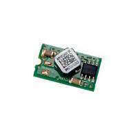
| 产品图片 |
|
| rohs | RoHS 合规性豁免无铅 / 符合限制有害物质指令(RoHS)规范要求 |
| 产品系列 | 隔离式DC/DC转换器,Murata Power Solutions BWR-15/330-D12A-CBWR |
| mouser_ship_limit | 该产品可能需要其他文档才能发货到中国。 |
| 数据手册 | |
| 产品型号 | BWR-15/330-D12A-C |
| 产品 | Isolated |
| 产品培训模块 | http://www.digikey.cn/PTM/IndividualPTM.page?site=cn&lang=zhs&ptm=21792 |
| 产品目录页面 | |
| 产品种类 | 隔离式DC/DC转换器 |
| 其它名称 | 811-1723-5 |
| 功率(W)-制造系列 | 10W |
| 功率(W)-最大值 | 10W |
| 包装 | 管件 |
| 商标 | Murata Power Solutions |
| 大小/尺寸 | 2.00" 长 x 1.00" 宽 x 0.38" 高(50.8mm x 25.4mm x 9.7mm) |
| 安装类型 | 通孔 |
| 封装 | Tube |
| 封装/外壳 | 5-DIP 模块 |
| 工作温度 | -40°C ~ 100°C |
| 工厂包装数量 | 16 |
| 效率 | 84% |
| 标准包装 | 16 |
| 特性 | - |
| 电压-输入(最大值) | 18V |
| 电压-输入(最小值) | 9V |
| 电压-输出1 | 15V |
| 电压-输出2 | -15V |
| 电压-输出3 | - |
| 电压-隔离 | 1kV(1000V) |
| 电流-输出(最大值) | 330mA,330mA |
| 类型 | 隔离模块 |
| 系列 | BWR |
| 绝缘电压 | 1.5 kV |
| 输入电压—公称值 | 12 V |
| 输入电压范围 | 9 V to 18 V |
| 输出功率 | 5 W |
| 输出数 | 2 |
| 输出电压—通道1 | +/- 15 V |
| 输出电压—通道2 | 15 V |
| 输出电流—通道1 | +/- 330 mA |
| 输出电流—通道2 | +/- 330 mA |
| 输出端数量 | 2 |
| 零件号别名 | BWR-15/330-D12A-C |


- 商务部:美国ITC正式对集成电路等产品启动337调查
- 曝三星4nm工艺存在良率问题 高通将骁龙8 Gen1或转产台积电
- 太阳诱电将投资9.5亿元在常州建新厂生产MLCC 预计2023年完工
- 英特尔发布欧洲新工厂建设计划 深化IDM 2.0 战略
- 台积电先进制程称霸业界 有大客户加持明年业绩稳了
- 达到5530亿美元!SIA预计今年全球半导体销售额将创下新高
- 英特尔拟将自动驾驶子公司Mobileye上市 估值或超500亿美元
- 三星加码芯片和SET,合并消费电子和移动部门,撤换高东真等 CEO
- 三星电子宣布重大人事变动 还合并消费电子和移动部门
- 海关总署:前11个月进口集成电路产品价值2.52万亿元 增长14.8%


PDF Datasheet 数据手册内容提取
BWR Models www.murata-ps.com 7-10W, Dual Output DC-DC converters Typical units FEATURES PRODUCT OVERVIEW Low cost! Highly reliable! It’s hard to beat the combination of low cost, small size (standard 2" x 1" x 0.375" package) proven reliability and outstanding electrical performance offered by the 7-10W, dual-output Proven SMT-on-pcb construction models of MPS’s new A-Series DC/DC converters. These highly effi cient, rugged convert- Qual tested; HALT tested; EMC tested ers combine straightforward circuit topologies, the newest components, proven SMT-on-pcb Designed to meet UL/EN60950-1 construction methods, and highly repeatable automatic-assembly techniques. Their superior Output voltages: ±5, ±12 or ±15 Volts durability is substantiated by a rigorous in-house qualifi cation program that includes HALT (Highly Accelerated Life Testing). Wide input voltage ranges: The wide input voltage ranges of these A-Series duals (4.7-7.25V for "D5A" models, 4.7-7.25V, 9-18V or 18-75V 9-18V for "D12A" models and 18-75V for "D48A" models) make them excellent candidates Small packages, 2" x 1" x 0.375" for battery-powered systems or for distributed power architectures. Their ±5, ±12 or ±15 Volt Industry-standard pinouts outputs cover virtually all standard applications. Fully isolated, 1500Vdc guaranteed These popular power converters are fully isolated (1500Vdc guaranteed) and display excel- lent line and load regulation (±0.3% max. for line and ±1% max. for load). They are completely Guaranteed effi ciencies to 82% I/O protected (input overvoltage shutdown and reverse-polarity protection, output current limit- –40 to +100°C operating temperature ing and overvoltage protection) and contain input (pi type) and output fi ltering to reduce noise. Modifi cations and customs for OEM’s They require no external components and offer true "plug-and-play" convenience. Select models are RoHS compliant These extremely reliable, cost-effective power converters carry industry-standard pinouts making them ideal replacements for other more costly, less reliable power converters in com- puter, telecom/datacom, instrumentation and ATE applications. They are an excellent choice for both new design-ins and upgrading older systems. +VIN +VOUT (1) (3) COMMON (4) –VIN –VOUT (2) (5) PWM OPTO REFERENCE & CONTROLLER ISOLATION ERROR AMP Typical topology is shown. Figure 1. Simplifi ed Schematic For full details go to www.murata-ps.com/rohs www.murata-ps.com/support MDC_BWR-7-10.F01 Page 1 of 5
BWR Models 7-10W, Dual Output DC-DC converters PERFORMANCE SPECIFICATIONS SUMMARY AND ORDERING GUIDE ➀ Output Input Effi ciency Package VOUT IOUT R/N (mVp-p) ➁ Regulation (Max.) VIN Nom. Range IIN ➃ Full Load (Case/ Model (Volts) (mA, Max.) Typ. Max. Line Load ➂ (Volts) (Volts) (mA) Min. Typ. Pinout) BWR-5/700-D48A-C* ±5 ±700 50 100 ±0.3% ±1.0% 48 18-75 15/180 79% 81% C2, P12 BWR-12/415-D12A-C* ±12 ±415 100 120 ±0.3% ±1.0% 12 9-18 20/986 83% 84% C2, P12 BWR-12/415-D48A-C* ±12 ±415 75 120 ±0.3% ±1.0% 48 18-75 15/249 80.5% 84% C2, P12 BWR-15/330-D12A-C* ±15 ±330 75 120 ±0.15% ±0.2% 12 9-18 25/980 83% 84% C2, P12 BWR-15/330-D48A-C* ±15 ±330 75 120 ±0.3% ±1.0% 48 18-75 15/250 80.5% 82.5% C2, P12 BWR-5/700-D5A-C ±5 ±700 50 75 ±0.3% ±1.0% 5 4.7-7.25 25/1772 76% 79% C2, P12 BWR-5/900-D12A-C* ±5 ±900 75 100 ±0.3% ±1.0% 12 9-18 25/930 81% 82% C2, P12 BWR-12/335-D5A-C ±12 ±335 75 120 ±0.3% ±1.0% 5 4.7-7.25 40/1846 76% 78% C2, P12 BWR-15/275-D5A-C ±15 ±275 75 120 ±0.3% ±1.0% 5 4.7-7.25 40/2089 75% 79% C2, P12 ➀ Typical at TA = +25°C under nominal line voltage and full-load conditions unless otherwise noted. * Magnetic feedback. ➁ Ripple/Noise (R/N) measured over a 20MHz bandwidth. ➂ Balanced loads, 20% to 100% load. ➃ Nominal line voltage, no-load/full-load conditions. PART NUMBER STRUCTURE MECHANICAL SPECIFICATIONS B WR-15/ 330 -D12 A-C 2.00 (50.80) METAL CASE Output Confi guration: RoHS-6 Compliance 0.375 Case C2 (9.53) B = Bipolar A-Series INSULATED BASE High Reliability Wide Range Input 0.040 ±0.002 DIA. 0.20 MIN Input Voltage Range: (5.08) (1.016 ±0.051) D5 = 4.7-7.25 Volts (5V nominal) 0.800 0.60 Nominal Output Voltages: D12 = 9-18 Volts (12V nominal) (20.32) (15.24) ±5, ±12 or ±15 Volts D48 = 18-75 Volts (48V nominal) Maximum Output Current 3 0.100 1 (2.54) in mA from each output (215.0.400) 2 4 (02.08.0302) Not all model combinations are available. Contact Murata Power Solutions. 0.400 (10.16) 5 TEMPERATURE DERATING 0.200 BOTTOM VIEW (5.08) 0.10 (2.54) DIMENSIONS ARE IN INCHES (MM) 10 A, B A 9 C B 8 D C D, E s) 7 E, F att er (W 6 F I/O Connections w put Po 5 BBWWRR--55//970000--DD152AA CE P1in Fun+cItniopnu tP12 Notes: Out 4 BBWWRR--152/7/3030-5D-D458AA DF 2 –Input For "D5A" and "D12A"models, the 3 BBWWRR--1122//441155--DD1428AA AA 3 +Output case is connected to pin 2 (–VIN). BWR-15/275-D5A D 4 Common For "D48A" models, the case 2 BBWWRR--1155//333300--DD1428AA AB 5 –Output is connected to pin 1 (+VIN). 1 0 –40 0 40 45 50 55 60 65 70 75 80 85 90 95 10 0 Ambient Temperature (°C) www.murata-ps.com/support MDC_BWR-7-10.F01 Page 2 of 5
BWR Models 7-10W, Dual Output DC-DC converters Performance/Functional Specifi cations Typical @ TA = +25°C under nominal line voltage and full-load conditions, unless noted. ➀ Input Absolute Maximum Ratings Input Voltage Range: Input Voltage: D5A Models 4.7-7.25 Volts (5V nominal) D5 Models 10 Volts D12A Models 9-18 Volts (12V nominal) D12 Models 20 Volts D48A Models 18-75 Volts (48V nominal) D48 Models 80Volts Input Current See Ordering Guide Input Reverse-Polarity Protection Current must be <6A. Brief Input Filter Type ➁ Pi duration only. Fusing recommended. Output Overvoltage Protection Reverse-Polarity Protection Yes (Instantaneous, 6A maximum) ±5V Outputs 13 Volts, limited duration Output ±12V Outputs 28 Volts, limited duration ±15V Outputs 36 Volts, limited duration VOUT Accuracy (50% load): ±5V Outputs ±1.5%, maximum Output Current Current limited. Max. current and ±12/15V Outputs ±1%, maximum short-circuit duration are model dependent. Temperature Coeffi cient ±0.02% per °C Ripple/Noise (20MHz BW) ➁ See Ordering Guide Storage Temperature –40 to +105°C Lead Temperature (soldering, 10 sec.) +300°C Line/Load Regulation See Ordering Guide Effi ciency See Ordering Guide These are stress ratings. Exposure of devices to any of these conditions may adversely Isolation Voltage ➂ 1500Vdc, minimum (functional) affect long-term reliability. Proper operation under conditions other than those listed in the Performance/Functional Specifi cations Table is not implied. Isolation Capacitance 200pF Current Limiting Auto-recovery Overvoltage Protection ➃ Zener/transorb clamps, magnetic feedback T E C H N I C A L N O T E S Dynamic Characteristics Transient Response (50% load step) 200µsec max. to ±1.5% of fi nal value Floating Outputs Switching Frequency 165kHz (±15kHz) Since these are isolated DC/DC converters, their outputs are "fl oating." Any Environmental BWR model may be confi gured to produce an output of 10V, 24V or 30V (for Operating Temperature (ambient): ±5V, ±12V or ±15V models, respectively) by applying the load across the Without Derating –40 to +65/70°C (Model dependent) +Output and –Output pins (pins 3 and 5), with either output grounded. The With Derating to +100°C (See Derating Curves) Common pin (pin 4) should be left open. Minimum 20% loading is recom- Storage Temperature –40 to +105°C mended under these conditions. Physical Dimensions 2" x 1" x 0.375" (51 x 25 x 9.5mm) Filtering and Noise Reduction Shielding 5-sided All A-Series BWR 7-10 Watt DC/DC Converters achieve their rated ripple Case Connection: and noise specifi cations without the use of external input/output capaci- D5A and D12A Models Pin 2 (–VIN) tors. In critical applications, input/output ripple and noise may be further D48A Models Pin 1 (+VIN) reduced by installing electrolytic capacitors across the input terminals and/ Case Material Corrosion resistant steel with or low-ESR tantalum or electrolytic capacitors across the output terminals. non-conductive, epoxy-based black Output capacitors should be connected between their respective output pin enamel fi nish and palstic baseplate (pin 3 or 5) and Common (pin 4) as shown in Figure 2. The caps should be Pin Material RoHS: Gold-plated copper alloy with nickel located as close to the power converters as possible. Typical values are underplate listed in the tables below. In many applications, using values greater than Non-RoHS: Solder-coated brass those listed will yield better results. Weight 1.3 ounces (37 grams) Flammability UL 94V-0 To Reduce Input Ripple "D5A" Models 47µF, 10V ➀ These power converters require a minimum 20% loading on each output to maintain "D12A" Models 20µF, 35V specifi ed regulation. Operation under no-load conditions will not damage these devices; however they may not meet all listed specifi cations. "D48A" Models 10µF, 100V ➁ Application-specifi c internal input/output fi ltering can be recommended or perhaps added internally upon request. Contact MPS Applications Engineering for details. To Reduce Output Ripple ➂ Devices can be screened or modifi ed for higher guaranteed isolation voltages. ±5V Output 47µF, 10V, Low ESR Contact MPS Applications Engineering for details. ➃ D5A Models: Zener/transorb only ±12/15V Outputs 22µF, 20V, Low ESR In critical, space-sensitive applications, MPS may be able to tailor the internal input/output fi ltering of these units to meet your specifi c requirements. Con- tact our Applications Engineering Group for additional details. www.murata-ps.com/support MDC_BWR-7-10.F01 Page 3 of 5
BWR Models 7-10W, Dual Output DC-DC converters EMI RADIATED EMISSIONS 3 +OUTPUT If you’re designing with EMC in mind, please note that all of MPS’s BWR 1 + 7-10 Watt A-Series DC/DC Converters have been characterized for radi- +INPUT COUT ated and conducted emissions in our new EMI/EMC laboratory. Testing is + 4 conducted in an EMCO 5305 GTEM test cell utilizing EMCO automated EMC CIN COMMON test software. Radiated emissions are tested to the limits of FCC Part 15, 2 + –INPUT COUT Class B and CISPR 22 (EN 55022), Class B. Correlation to other specifi ca- 5 tions can be supplied upon request. Radiated emissions plots to FCC and –OUTPUT CISPR 22 for model BWR-15/330-D48A appear below. Published EMC test reports are available for each model number. Contact MPS’s Applications Engineering Department for more details. Figure 2. Using External Capacitors to Reduce Input/Output Ripple/Noise BWR-15/330-D48A Radiated Emissions FCC Part 15 Class B, 3 Meters Converter Output = ±15Vdc @ ±300mA 80 Input Fusing 70 Certain applications and/or safety agencies may require the installation of 60 M) FCC Class B Limit fuses at the inputs of power conversion components. For MPS A-Series V/ 50 µ B BWR 7-10 Watt DC/DC Converters, you should use slow-blow type fuses s (d 40 with values no greater than the following: on si 30 s mi VIN Range Fuse Value d E 20 "D5A" 3A diate 10 "D12A" 2A Ra 0 "D48A" 1A Radiated Emissions –10 –20 C U S T O M C A P A B I L I T I E S 100 1000 Frequency (MHz) MPS’s world-class design, development and manufacturing team stands ready to work with you to deliver the exact power converter you need for BWR-15/330-D48A Radiated Emissions your demanding, large volume, OEM applications. And ... we’ll do it on EN 55022 Class B, 10 Meters time and within budget! Converter Output = ±15Vdc @ ±300mA Our experienced applications and design staffs; quick-turn prototype 80 capability; highly automated, SMT assembly facilities; and in-line SPC 70 quality-control techniques combine to give us the unique ability to design 60 and deliver any quantity of power converters to the highest standards of M) V/ 50 quality and reliability. dBµ EN 55022 Class B Limit s ( 40 We have compiled a large library of DC/DC designs that are currently used on si 30 in a variety of telecom, medical, computer, railway, aerospace and indus- mis trial applications. We may already have the converter you need. d E 20 e diat 10 Contact us. Our goal is to provide you the highest-quality, most cost- Ra 0 effective power converters available. Radiated Emissions –10 –20 100 1000 Frequency (MHz) www.murata-ps.com/support MDC_BWR-7-10.F01 Page 4 of 5
BWR Models 7-10W, Dual Output DC-DC converters Quality and Reliability corrective actions and/or design changes, stresses are stepped up again and the cycle is repeated until the "fundamental limit of the technology" is The A-Series are the fi rst DC/DC Converters to emerge from MPS’s new, determined. company-wide approach to designing and manufacturing the most reliable power converters available. The fi ve-pronged program draws our Quality MPS has invested in a Qualmark OVS-1 HALT tester capable of applying Assurance function into all aspects of new-product design, development, voltage and temperature extremes as well as 6-axis, linear and rota- characterization, qualifi cation and manufacturing. tional, random vibration. A typical HALT profi le (shown above) consists of thermal cycling (–55 to +125°C, 30°C/minute) and simultaneous, gradually Design for Reliability increasing, random longitudinal and rotational vibration up to 20G’s with Design for Reliability is woven throughout our multi-phased, new-product- load cycling and applied-voltage extremes added as desired. Many devices development process. Design-for-reliability practices are fully documented in MPS’s new A-Series could not be made to fail prior to reaching either and begin early in the new-product development cycle with the following the limits of the HALT chamber or some previously known physical limit of goals: the device. We also use the HALT chamber and its ability to rapidly cool 1. To work from an approved components/vendors list ensuring the use of devices to verify their "cold-start" capabilities. reliable components and the rigorous qualifi cation of new components. Qualifi cation 2. To design with safety margins by adhering to a strict set of derating guidelines and performing theoretical worst-case analyses. For each new product, electrical performance is verifi ed via a comprehen- 3. To locate potential design weaknesses early in the product-development sive characterization process and long-term reliability is confi rmed via a cycle by using extensive HALT (Highly Accelerated Life Testing). rigorous qualifi cation procedure. The qual procedure includes such strenu- 4. To prove that early design improvements are effective by employing a ous tests as thermal shock and 500 hour life. Qual testing is summarized thorough FRACA (Failure Reporting Analysis and Corrective Action) system. below. Qualifi cation Testing HALT Testing Qualifi cation Test Method/Comments The goal of the accelerated-stress techniques used by MPS is to force HALT MPS in-house procedure device maturity, in a short period of time, by exposing devices to excessive High Temperature Storage Max. rated temp., 1,000 hours levels of "every stimulus of potential value." We use HALT (Highly Acceler- Thermal Shock 10 cycles, –55 to +125°C ated Life Testing) repeatedly during the design and early manufacturing Temperature/Humidity +85°C, 85% humidity, 48 hours phases to detect potential electrical and mechanical design weaknesses that could result in possible future fi eld failures. Lead Integrity MPS in-house procedure Life Test +70°C, 500 hours* During HALT, prototype and pre-production DC/DC converters are sub- Marking Permanency MPS in-house procedure jected to progressively higher stress levels induced by thermal cycling, End Point Electrical Tests Per product specifi cation rate of temperature change, vibration, power cycling, product-specifi c * Interim electrical test at 200 hours. stresses (such as dc voltage variation) and combined environments. The In-Line Process Controls and Screening stresses are not meant to simulate fi eld environments but to expose any A combination of statistical sampling and 100% inspection techniques weaknesses in a product’s electro/mechanical design and/or assem- keeps bly processes. The goal of HALT is to make products fail so that device our assembly line under constant control. Parameters such as solder-paste weaknesses can be analyzed and strengthened as appropriate. Applied thickness, component placement, cleanliness, etc. are statistically sampled, stresses are continually stepped up until products eventually fail. After charted and fi ne tuned as necessary. Visual inspections are performed by Typical HALT Profi le trained operators after pick-and-place, soldering and cleaning operations. 100 Units are 100% electrically tested prior to potting. All devices are tem- perature cycled, burned-in, hi-pot tested and fi nal-electrical tested prior to 80 40 external visual examination, packing and shipping. 60 Rapid Response to Problems e 40 20 eatu atin MPS employs an outstanding corrective-action system to immediately e 20 ib address any detected shortcomings in either products or processes. When- 0 0 Rand ever our assembly, quality or engineering personnel spot a product/process problem, or if a product is returned with a potential defect, we immediately –20 perform a detailed failure analysis and, if necessary, undertake corrective –40 10 20 30 40 50 60 70 80 90 actions. Over time, this system has helped refi ne our assembly operation to et i e inute yield one of the lowest product defect rates in the industry. This product is subject to the following operating requirements Murata Power Solutions, Inc. and the Life and Safety Critical Application Sales Policy: 11 Cabot Boulevard, Mansfi eld, MA 02048-1151 U.S.A. Refer to: http://www.murata-ps.com/requirements/ ISO 9001 and 14001 REGISTERED Murata Power Solutions, Inc. makes no representation that the use of its products in the circuits described herein, or the use of other technical information contained herein, will not infringe upon existing or future patent rights. The descriptions contained herein do not imply the granting of licenses to make, use, or sell equipment constructed in accordance therewith. Specifi cations are subject to change without notice. © 2014 Murata Power Solutions, Inc. www.murata-ps.com/support MDC_BWR-7-10.F01 Page 5 of 5
Mouser Electronics Authorized Distributor Click to View Pricing, Inventory, Delivery & Lifecycle Information: M urata: BWR-12/415-D12A-C BWR-12/415-D48A-C BWR-15/330-D12A-C BWR-15/330-D48A-C BWR-5/700-D48A-C