ICGOO在线商城 > 集成电路(IC) > 接口 - 编码器,解码器,转换器 > BU94603KV-E2
 Datasheet下载
- 型号: BU94603KV-E2
- 制造商: ROHM Semiconductor
- 库位|库存: xxxx|xxxx
- 要求:
| 数量阶梯 | 香港交货 | 国内含税 |
| +xxxx | $xxxx | ¥xxxx |
查看当月历史价格
查看今年历史价格
BU94603KV-E2产品简介:
ICGOO电子元器件商城为您提供BU94603KV-E2由ROHM Semiconductor设计生产,在icgoo商城现货销售,并且可以通过原厂、代理商等渠道进行代购。 BU94603KV-E2价格参考¥23.65-¥23.65。ROHM SemiconductorBU94603KV-E2封装/规格:接口 - 编码器,解码器,转换器, IC DECODER USB HOST AUDIO 64VQFP。您可以下载BU94603KV-E2参考资料、Datasheet数据手册功能说明书,资料中有BU94603KV-E2 详细功能的应用电路图电压和使用方法及教程。
| 参数 | 数值 |
| 产品目录 | 集成电路 (IC)半导体 |
| DAC数量 | 1 |
| 描述 | IC DECODER USB HOST AUDIO 64VQFP接口—CODEC USB HOST MP3 DECODER |
| 产品分类 | 线性 - 音频处理集成电路 - IC |
| 品牌 | Rohm Semiconductor |
| 产品手册 | |
| 产品图片 |
|
| rohs | 符合RoHS无铅 / 符合限制有害物质指令(RoHS)规范要求 |
| 产品系列 | 接口 IC,接口—CODEC,ROHM Semiconductor BU94603KV-E2- |
| 数据手册 | |
| 产品型号 | BU94603KV-E2 |
| THD+噪声 | 0.02 % |
| 产品培训模块 | http://www.digikey.cn/PTM/IndividualPTM.page?site=cn&lang=zhs&ptm=30054 |
| 产品种类 | 接口—CODEC |
| 供应商器件封装 | 64-VQFP(10x10) |
| 信噪比 | 96 dB |
| 其它名称 | BU94603KV-E2CT |
| 包装 | 剪切带 (CT) |
| 商标 | ROHM Semiconductor |
| 安装类型 | 表面贴装 |
| 安装风格 | SMD/SMT |
| 封装 | Reel |
| 封装/外壳 | 64-LQFP |
| 封装/箱体 | VQFP-64 |
| 工作电源电压 | 3 V to 3.6 V |
| 工厂包装数量 | 1000 |
| 应用 | 音频 |
| 接口类型 | I2C |
| 最大工作温度 | + 85 C |
| 最小工作温度 | - 40 C |
| 标准包装 | 1 |
| 特色产品 | http://www.digikey.cn/product-highlights/cn/zh/rohm-usb-mp3-audio-media-decoder/3654 |
| 电源电流 | 65 mA |
| 类型 | 音频解码器 |
| 转换速率 | 48 kHz |


PDF Datasheet 数据手册内容提取
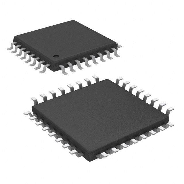
Datasheet USB Audio Decoder LSI Series AAC/WMA/MP3 +SD Memory Card + iPod BU94601KV BU94603KV BU94604BKV ●Description ●Package W(Typ.) x D(Typ.) x H(Max.) BU94601KV / BU94603KV / BU94604BKV are AAC+ WMA + MP3 decoder IC which contains USB host, SD card I/F, audio DAC, system controller, and regulator for internal CORE power supply. ●Features (cid:132) USB2.0 Full Speed host I/F function contained. (cid:132) Protocol conversion from I2C to USB HID or from USB HID to I2C. (Only BU94604BKV) (cid:132) SD card I/F function contained. (cid:132) I2C I/F function contained. (cid:132) FAT analysis function contained. (cid:132) MP3 decode function contained. (available for MPEG1, 2 and 2.5, Layer 1, 2 and 3) (cid:132) WMA decode function contained. (Except BU94601KV) VQFP64 Available for WMA9 standard and not available for 12.00mm x 12.00mm x 1.60mm DRM (cid:132) AAC decode function contained. (Except BU94601KV) Available for MPEG4 AAC-LC and not available for DRM (cid:132) Sample Rate Converter contained. (cid:132) System Controller contained. (cid:132) LED Controller contained. (cid:132) KEY matrix Controller contained. (cid:132) Stand Alone mode contained. (cid:132) External processor can control. (Slave mode) (cid:132) Audio DAC contained. (cid:132) Sound Effect function contained. (cid:132) Digital Audio Output(I2S, S/PDIF) function contained. (cid:132) File Name, Folder Name Sorting. (cid:132) ID3TAG and WMATAG and AACTAG Analysis. (cid:132) Reading a specified file data is possible from USB memory. (cid:132) LUN is selectable. (cid:132) Regulator for internal CORE power supply contained. (cid:132) VQFP64pin(0.5mm pitch) ●Applications Audio products, etc ●Line up Part number Format iPod Package Ordering part number BU94601KV MP3 VQFP64 Reel of 2000 BU94601KV-ZAE2 Not supported BU94603KV AAC/WMA/MP3 VQFP64 Reel of 2000 BU94603KV-ZAE2 BU94604BKV AAC/WMA/MP3 Supported VQFP64 Reel of 2000 BU94604BKV-ZAE2 ○Product structure:Silicon Monolithic integrated circuit ○Radiation resistance design is not arranged www.rohm.com TSZ02201-0V2V0E600010-1-2 © 2012 ROHM Co., Ltd. All rights reserved. 1/66 TSZ22111・14・001 2012.07.12 Rev.001
DDaattaasshheeeett BU94601KV BU94603KV BU94604BKV ●Basic circuit application diagram-part1 Figure 1. an example of connection circuit application (BU94601KV/BU94603KV/BU94604BKV MODE1) * Figure 2. an example of connection circuit application (BU94601KV/BU94603KV MODE2/3) * www.rohm.com TSZ02201-0V2V0E600010-1-2 © 2012 ROHM Co., Ltd. All rights reserved. 2/66 TSZ22111・15・001 2012.07.12 Rev.001
DDaattaasshheeeett BU94601KV BU94603KV BU94604BKV ●Basic circuit application diagram-part2 Figure 3. an example of connection circuit application (BU94604BKV MODE2/3) * This LSI has built in regulator for internal CORE power supply. DVDD terminal of 27PIN and 57PIN connect to bypass condenser. DVDD terminal of 27PIN and 57PIN don’t connect to power supply. The reference circuit and reference circuit parameters for crystal oscillator are shown above. The circuit parameters introduced above is not taking into consideration the environment in customer’s systems or set‘s board. Therefore, ROHM is not guaranteed this content in any circuits. Please check the optimal circuit parameter in customer’s actual systems or products with the oscillator manufacturer. www.rohm.com TSZ02201-0V2V0E600010-1-2 © 2012 ROHM Co., Ltd. All rights reserved. 3/66 TSZ22111・15・001 2012.07.12 Rev.001
DDaattaasshheeeett BU94601KV BU94603KV BU94604BKV ●Difference of BU94601KV/BU94603KV/BU94604BKV features Item BU94601KV BU94603KV BU94604BKV Package VQFP64 Number of pins 64pin Power supply 3.3V (inner 1.5V regulator ) USB Full speed(12Mbps) USB Host I/F USB mass storage class SPI mode SD Card I/F SD, SDHC, MMC, mini-SDcard I2C command I/F(Slave) Supported Audio line output Supported I2S Digital audio output SPDIF Sample rate converter Supported clock 16.9344MHz Playable MP3 files *.mp3,*.mp2,*.mp1 Playable WMA files Not supported *.asf,*.wma Playable AAC files Not supported *.m4a,*.3gp,*.mp4 iPod Not supported Supported*1 *1 For using of BU94604BKV, It is necessary to become a licensee of Apple Inc. regarding "Made for iPod/iPhone/iPad License". www.rohm.com TSZ02201-0V2V0E600010-1-2 © 2012 ROHM Co., Ltd. All rights reserved. 4/66 TSZ22111・15・001 2012.07.12 Rev.001
DDaattaasshheeeett BU94601KV BU94603KV BU94604BKV ●Block diagram MP3/WMA/ SRC USB AAC Decoder * I/F File Data I2S System I2S Out Buffer OUT (FAT16/32) TAG Analysis SPDIF SD SPDIF Out OUT I/F System Controller USB/ 16.9344 Audio Power System MHz DAC AMP PLL Command 3.3V 1.5V LDO I/F (I2C) /SD Title5.SONG_E 01:10AAlrbtuismtAARLTBIUSMTAZ MCU User I/F Main Control Block *BU94601KV contains only MP3 decoder Figure 4. Block diagram www.rohm.com TSZ02201-0V2V0E600010-1-2 © 2012 ROHM Co., Ltd. All rights reserved. 5/66 TSZ22111・15・001 2012.07.12 Rev.001
DDaattaasshheeeett BU94601KV BU94603KV BU94604BKV ●Arrangement of Terminals BU94601KV / BU94603KV / BU94604BKV Figure 5. Arrangement of Terminals www.rohm.com TSZ02201-0V2V0E600010-1-2 © 2012 ROHM Co., Ltd. All rights reserved. 6/66 TSZ22111・15・001 2012.07.12 Rev.001
DDaattaasshheeeett BU94601KV BU94603KV BU94604BKV ●Description of Terminals STAND ALONE MODE (MODE1) SLAVE MODE (MODE2,MODE3) Pull-Up/ Pull-Up/ Pin I/O Signal Name I/O Down Function Signal Name I/O Down Function No. Cir (*7) (*7) H: Release RESET, 1 RESETX A I PU ← L: RESET 2 SEL_SLAVE B I PU(*1) H: STAND ALONE, L:SLAVE ← H: PLAY MP3 ONLY, 3 SEL_MP3 B I PU(*1) ← L: PLAY MP1,MP2 and MP3 H: Audio Line Output, 4 SEL_DOUT B I PU(*1) ← L: Digital Audio Output H: Volume control valid, 5 SEL_VOL B I PU(*1) ← L: Volume control invalid H: Auto Play OFF , 6 SEL_APLAY B I PU(*1) ← L: Auto Play H: Normal Operation 7 SEL_UTPKT B I PU(*1) ← L: USB Test Packet Output TEST1 (*2) B O - OPEN (for TEST) ← 8 Device (Have 2 configuration IRPTO (*3) B O - or more) connection’s ← interruption output terminal Pull-up to 3.3V system power 9 TEST2 - I PU ← supply (for TEST) 10 KEY_ROW1 B I PU KEY Input ROW1 MCHNG O - Music change Output Command 11 KEY_ROW2 B I PU KEY Input ROW2 BUSY O - Operation Busy Flag 12 KEY_ROW3 B I PU KEY Input ROW3 SCL I - I2C I/F Clock Input I2C I/F Data 13 KEY_ROW4 B I PU KEY Input ROW4 SDA I/O - Input/Output I2C I/F Slave 14 KEY_COL1 B O - KEY Input COLUMN1 A0 I - Address Set0 I2C I/F Slave 15 KEY_COL2 B O - KEY Input COLUMN2 A1 I - Address Set1 16 KEY_COL3 B O - KEY Input COLUMN3 SEL_SMAN I PU(*1) H: MODE2, L: MODE3 Pull-up to 3.3V system power 17 TEST3 B I PU ← supply (for TEST) Connect to 3.3V 18 DVDDIO - - - ← System Power Supply 19 SD_CON B I - SD I/F (*4) ← 20 SD_DO B I - SD I/F (*4) ← 21 SD_CLK B O - SD I/F ← 22 SD_DI B O - SD I/F ← 23 SD_CS B O - SD I/F ← 24 DVSS - - - Connect to GND ← Pull-up to 3.3V system power 25 TEST4 - I PU ← supply (for TEST) Pull-up to 3.3V system power I/O 26 TEST5 - I PU CLKOUT12(*5) PU(*5) 12MHz CLK Output. supply (for TEST) (*5) 27 DVDD_M2 - - - Connect to 57PIN ← Pull-up to 3.3V system power 28 TEST6 - I - ← supply (for TEST) Pull-up to 3.3V system power 29 TEST7 - I - ← supply (for TEST) Pull-up to 3.3V system power 30 TEST8 - I - ← supply (for TEST) 31 ATEST1 - O - OPEN (for TEST) ← Connect to 3.3V 32 AVDDC - - - ← System Power Supply 33 USB_DM C I/O - USB DATA- ← 34 USB_DP C I/O - USB DATA+ ← 35 AVSSC - - - Connect to GND ← USB bias resistor(12kΩ) connecting terminal. Arrange the resistance of 36 REXTI D O - ← 12kΩ near PIN, and wiring on the PIN side doesn’t cross with other signal lines. www.rohm.com TSZ02201-0V2V0E600010-1-2 © 2012 ROHM Co., Ltd. All rights reserved. 7/66 TSZ22111・15・001 2012.07.12 Rev.001
DDaattaasshheeeett BU94601KV BU94603KV BU94604BKV 37 VOREFI - O - OPEN (for TEST) ← Connect to 3.3V 38 VDD_PLL - - - ← System Power Supply 39 TEST_PLL - I - OPEN (for TEST) ← 40 XIN_PLL E I - X'tal Input 16.9344MHz ← 41 XOUT_PLL E O - Connect to X'tal 16.9344MHz ← 42 VSS_PLL - - - Connect to GND ← 43 DAVSS - - - Connect to GND ← 44 RDACO F O - Audio DAC Line Output Rch ← Audio DAC 45 VCDACO I O - ← Reference Voltage Output 46 LDACO F O - Audio DAC Line Output Lch ← Connect to 3.3V 47 DAVDD - - - ← System Power Supply Audio Mute Output 48 AMUTE G O - ← (H:Mute Cancel, L:Mute) Pull-up to 3.3V system 49 LED_ERROR B O - Error LED Output TEST9 I PU power supply Pull-up to 3.3V system 50 LED_PLAY B O - Play LED Output TEST10 I PU power supply Pull-up to 3.3V system 51 LED_PSD B O - Play SD Card LED Output TEST11 I PU power supply Pull-up to 3.3V system 52 LED_PUSB B O - Play USB LED Output TEST12 I PU power supply I2S Output LRCK I/O 53 LED_ACCESS B O - Memory Access LED Output PU(*6) LR Clock / /SPDIF(*4) (*6) SPDIF Output I/O 54 LED_RANDOM B O - Random Play LED Output BCK(*4) PU(*6) I2S Output Bit Clock (*6) I/O 55 LED_REPEAT B O - Repeat Play LED Output DATA(*4) PU(*6) I2S Output LR DATA (*6) Pull-up to 3.3V system power 56 TEST13 - I PU ← supply (for TEST) Connect to 57 DVDD_M1 - - - ← Bypass Condenser 58 TEST14 F I - Connect to GND ← Pull-up to 3.3V system power 59 TEST15 - I - ← supply (for TEST) Pull-up to 3.3V system power 60 TEST16 - I - ← supply (for TEST) Pull-up to 3.3V system power 61 TEST17 - I - ← supply (for TEST) 62 DVSS - - - Connect to GND ← 63 TMODE H I - Connect to GND ← Connect to 3.3V 64 DVDDIO - - - ← System Power Supply *1 When L is input, Pull-UP turns OFF. *2 BU94601KV / BU94603KV *3 BU94604BKV *4 When SD I/F is disused, pull-up to 3.3V system power supply. *5 Enabled/Disabled can be selected using commands. This pin becomes output and pull-up is OFF, only when 12MHz clock output is enable. *6 In STAND ALONE MODE (MODE1), When Audio Line output is selected (SEL_DOUT=H), LED output is enabled. When the Digital Audio output is selected (SEL_DOUT=L), the I2S format audio output is enabled. In SLAVE MODE (MODE2, MODE3), When the Analog Line output is selected (SEL_DOUT=H), these pins are TEST terminals. When the Digital Audio output is selected (SEL_DOUT=L), I2S or SPDIF is selectable. See Chapter 4 . SEL_DOUT for further information. *7 Input L level directly without resistance when you input L to the terminal with Pull-Up (about 33 kΩ). www.rohm.com TSZ02201-0V2V0E600010-1-2 © 2012 ROHM Co., Ltd. All rights reserved. 8/66 TSZ22111・15・001 2012.07.12 Rev.001
DDaattaasshheeeett BU94601KV BU94603KV BU94604BKV ●Terminal equivalent circuit diagram A B C D DVDDIO DVDDIO DVDDIO DVDDIO DP AVDDC AVDDC D M 15KΩ 15KΩ DVSSIO DVSSIO AVSSC AVSSC AVSSC E F G H DAVDD DVDDIO DVDDIO VDD_PLL VDD_PLL XIN XOUT VSS_PLL VSS_PLL DAVSS DVSSIO DVSSIO I DAVDD DAVSS www.rohm.com TSZ02201-0V2V0E600010-1-2 © 2012 ROHM Co., Ltd. All rights reserved. 9/66 TSZ22111・15・001 2012.07.12 Rev.001
DDaattaasshheeeett BU94601KV BU94603KV BU94604BKV ●Description of each block’s movement-part1 · BU94601KV/BU94603KV/BU94604BKV are AAC+WMA+MP3 decoder IC in which a USB host I/F, SD memory card I/F, audio DAC and system control functions are built. Using a KEY or I2C interface command, the IC reads out a MP3 file written to a memory device having a USB I/F or a SD memory card. All the operations required before the data can be output to audio devices are incorporated into one chip. *BU94601KV supports only MP3. · Supporting STAND ALONE MODE which is enabled by commands entered from the keyboard (hereinafter referred to as MODE1), AUTO SLAVE MODE which is enabled by commands entered from the master microcomputer, same as those entered from the keyboard, via the built-in I2C interface (hereinafter referred to as MODE2) and MANUAL SLAVE MODE which can send the memory device information to the master microcomputer via the I2C interface and completely control sequences such as a play sequence by the master microcomputer (hereinafter referred to as MODE3). · I2C bus <-> USB protocol conversion function built into. *Only MODE2 and MODE3 of BU94604BKV. · Supporting fast forward playing and fast backward playing with music. · Supporting outputs folder names, file names, ID3TAG (V1.0, V1.1 V2.2 V2.3 and V2.4) information and WMA-TAG information and AAC-TAG(iTunes Meta-data) information via the I2C interface. This function is enabled only in MODE 2 and MODE 3. · Supporting audio line output, digital audio output (I2S, SPDIF). · Reading a specified file data is possible from USB memory. *Only a file that exists in root folder corresponds. 1. USB host I/F · Builds in the USB Full speed (12 Mbps) HOST control function. · Supports the USB mass storage class. · Convert the protocol from I2C from USB(HID) and USB(HID) to I2C when communicating with the master microcomputer.* · An isochronous IN transfer function to 192 byte/Frame is built into.* . Interrupt IN transfer function is built into.* . It doesn't correspond to external HUB. * Only the device with two CONFIGURATIONS or more. Only BU94604BKV. 2. SD card I/F · Supports the SPI mode. · Supports the MMC and mini-SD cards. · Supports the SDHC cards. · Supports the SD ver1.01 (file system). · Does not support CPRM. 3. I2C I/F · Communicates with the master microcomputer using an I2C interface format. · Supports the standard mode (100 kbps) and fast mode (400 kbps). · Supports a 7-bit address. · Can select four types of slave addresses. 4. Audio output · 1bit-DAC output · Builds in the digital soft mute function. · Supports digital audio output (I2S, SPDIF). · Builds in sound effects of POPS, JAZZ, ROCK, CLASSIC, R&B and BassBoost.* * Only audio line output is enabled. www.rohm.com TSZ02201-0V2V0E600010-1-2 © 2012 ROHM Co., Ltd. All rights reserved. 10/66 TSZ22111・15・001 2012.07.12 Rev.001
DDaattaasshheeeett BU94601KV BU94603KV BU94604BKV ●Description of each block’s movement-part2 5. FAT analysis · Supports FAT16 and FAT 32. · Supports VFAT (long file name). · Supports multi-partition up to 1. · The maximum number of playable folders within each folder is 65534. · The maximum number of playable files within each folder is 65534. · The maximum number of playable folders within each device is 65534. · The playable folder hierarchy is up to 8 layers containing the root directory. · The playable file extension supports *.m4a, *.3gp, and *.mp4 for AAC, *.wma and *.asf for WMA, *.mp3, *.mp2, and *.mp1 for MP3. For *.mp2 and *.mp1, play enabled/disabled can be selected. Upper case letters and lower case letters are not distinguished in the file extension. (BU94601KV supports only *.mp3, *.mp2, and *.mp1.) · Sorts and plays up to 100 folders and 100 files in the order of UNICODE. · Possible to obtain up to 64 bytes as the folder name or file name. · Supports 1 sector of 512, 1024, 2048 and 4096 bytes. · Playable file size is up to 2Gbyte-1 byte. Although a file over 2Gbyte is recognized as a playable file, 2Gbyte -1byte part of the file is playable. 6. MP3 decoder · Supports MPEG audio 1, 2 and 2.5. · Supports Layer 1, 2 and 3. · Supports sample rates 8k, 16k, 32k, 11.025k, 22.05k, 44.1k, 12k, 24k and 48kHz. · Supports bit rate 8 to 320 kbps and VBR (Variable Bit Rate). *Except free format. · Supports ID3TAG V1.0, V1.1, V2.2, V2.3 and V2.4. (Up to 64 bytes can be obtained for the names of album, artist, and title.) 7. WMA decoder (BU94601KV doesn’t support.) · Supports Windows Media Audio 9 standard. · Not supports DRM. · Supports sample rates 8k, 16k, 32k, 11.025k, 22.05k, 44.1k, and 48kHz. · Supports bit rate 5 to 384 kbps and VBR (Variable Bit Rate). *Except free format. · Supports WMA-TAG. (Up to 64 bytes can be obtained for the names of album, artist, and title.) 8. AAC decoder (BU94601KV doesn’t support.) · Supports MPEG4 AAC-LC encoded by iTunes. · Not supports DRM. · Supports sample rates 8k, 16k, 32k, 11.025k, 22.05k, 44.1k, 12k, 24k and 48kHz. · Supports bit rate 8 to 320 kbps and VBR (Variable Bit Rate). · Supports AAC-TAG(iTunes Meta-data). (Up to 64 bytes can be obtained for the names of album, artist, and title.) · The playable file extension supports *.m4a, *.3gp, and *.mp4 · Based on 3GPP TS 26.244. · Supports file type of m4a, mp42, and 3gpX (numbers with arbitrary X). *About except for the file encoded by iTunes, when the stream of a gap or video data is included in the file, it may skip to the following music or skipping may be carried out. 9. Sample rate converter · Converts all the supported sample rates to 44.1 kHz using a poly-phase operation. 10. System controller · Controls all the system operations including KEY input, LED output, interface control with the master microcomputer, USB device access, SD card access, FAT analysis, sort function, MP3 decode, WMA decode and audio output. www.rohm.com TSZ02201-0V2V0E600010-1-2 © 2012 ROHM Co., Ltd. All rights reserved. 11/66 TSZ22111・15・001 2012.07.12 Rev.001
DDaattaasshheeeett BU94601KV BU94603KV BU94604BKV ●Description of each block’s movement-part3 11. KEY matrix controller · Controls 12 types of KEY inputs: play/pause, stop, tune forward/fast forward playing, tune backward/fast backward playing, folder forward, folder backward, 10-tune forward, volume up, volume down, repeat play, random play and device selection. 12. LED controller · Controls 7 types of LED outputs: play/pause, error, memory accessing, random playing, repeat playing, USB selection and SD selection 13. Control from the master microcomputer · Control from the master microcomputer is enabled using the I2C interface. · Through the command operations, the following can be controlled: play, pause, stop, tune forward, tune backward, fast forward playing, fast backward playing, folder forward, folder backward, 10-tune forward, 10-tune backward, volume up, volume down, device selection, volume setting, repeat selection, random play, digital audio output setting, sound effect setting, resume data setting and direct tune selection data setting. · Controls the following: playing status output, pause, stop, searching, error, folder number, file number within folder, play time information, number of total folders, number of total files, name of folder being played, name of file being played, ID3TAG (title, artist and album) , WMATAG (title, artist and album), AACTAG (title, artist and album),resume data and direct tune selection data (MODE3). 14. Function selection · Selects MODE1 or MODE2/3 (SEL_SLAVE=H: MODE1, L: MODE2/3). · Selects MPEG Audio Layer (SEL_MP3=H: play MP3 only, L: play MP1/MP2/MP3) · Digital audio output selection (SEL_DOUT=H: output OFF, L: output ON) · Sound volume operation selection (SEL_VOL=H: volume adjustable, L: volume not adjustable MAX output) · Selects operation at power ON to check device (SEL_APLAY=H: stop, L: play). *Enabled in MODE 1 only. · Selects MODE2 or MODE3 (SEL_SMAN=H: MODE2, L: MODE3). *Enabled in MODE 2/3 only. 15. File Read function in USB memory · The specified data of file that exists in the root folder of the USB memory reading is possible. * The file name corresponds only by 8.3 forms. (The wild-card cannot be used.) www.rohm.com TSZ02201-0V2V0E600010-1-2 © 2012 ROHM Co., Ltd. All rights reserved. 12/66 TSZ22111・15・001 2012.07.12 Rev.001
DDaattaasshheeeett BU94601KV BU94603KV BU94604BKV ●Absolute maximum ratings (Ta = 25℃) Parameter Symbol Limits Unit Comment Supply voltage(Analog, I/O) VDD1MAX -0.3 to 4.5 V DVDDIO, VDD_PLL, DAVDD, AVDDC Input voltage VIN -0.3 to VDD1 + 0.3 V Storage temperature range TSTG -55 to 125 ℃ Operating temperature TOPR -40 to 85 ℃ range Power dissipation *1 PD 750 mW *1:In the case of use at Ta=25℃ or more, 7.5mW should be reduced per 1℃. Radiation resistance design is not arranged. ●Operating conditions (Ta = 25℃) Parameter Symbol Limits Unit Comment Supply voltage(Analog, I/O) VDD1 3.0 to 3.6 V DVDDIO,VDD_PLL, DAVDD, AVDDC ●Electrical characteristics (Unless specified, Ta=25℃,VDD1=3.3V, DVSS=AVSSC=VSS_PLL=DAVSS=0V, XIN_PLL=16.9344MHz) Limits Parameter Symbol Unit Condition MIN. TYP. MAX. <Total > Circuit current (VDD1 IDD1USB1 - 65 80 mA *1 When USB memory is USB1) played. Circuit current (VDD1 SD1) IDD1SD1 - 35 50 mA *1 When SD card is played. <Digital block> H-Level input voltage VIH VDD1*0.7 - VDD1 V *3 L-Level input voltage VIL DVSS - VDD1*0.3 V *3 H-Level output voltage1 VOH1 VDD1-0.4 - VDD1 V IOH=-1.6mA, *4 L-Level output voltage1 VOL1 0 - 0.4 V IOL=1.6mA. *4 H-Level output voltage2 VOH2 VDD1-0.4 - VDD1 V IOH=-3.6mA, *5 L-Level output voltage2 VOL2 0 - 0.4 V IOL=3.6mA, *5 H-Level output voltage3 VOH3 VDD1-0.4 - VDD1 V IOH=-0.6mA, *6 L-Level output voltage3 VOL3 0 - 0.4 V IOL=0.6mA, *6 H-Level output voltage4 VOH4 VDD1-1.0 - VDD1 V IOH=-0.6mA, *7 L-Level output voltage4 VOL4 0 - 1.0 V IOL=0.6mA, *7 <USB-HOST > H-Level input voltage VIHUSB VDD1*0.6 - VDD1 V *8 L-Level input voltage VILUSB AVSSC - VDD1*0.3 V *8 Output impedance(H) ZOH 22.0 45.0 60.0 Ω *8 Output impedance(L) ZOL 22.0 45.0 60.0 Ω *8 H-Level output voltage VOHUSB VDD1-0.5 - VDD1 V *8 L-Level output voltage VOLUSB 0 - 0.3 V *8 Rise/Fall time Tr/Tf - 11 - ns *8, Output capacity 50pF Voltage of crossing point VCRS - VDD1/2 - V *8, Output capacity 50pF Range of differential input VDIFF 0.8 - 2.5 V *8 Differential input sensitivity VSENS 0.2 - - V *8 Pull-down resistance RPD 14.25 15.0 24.8 kΩ *8 <Audio DAC> Distortion rate THD - 0.02 - % 1kHz, 0dB, sine, *9 Dynamic range DR - 88 - dB 1kHz, -60dB, sine, *9 S/N ratio S/N - 96 - dB *9 Max output level VSMAX - 0.92 - Vrms 1kHz, 0dB, sine, no load, *9 *1 3.3V system I/O, Analog Power supply(VDD1), 1kHz, 0dB, sine-wave playing *3 1-7, 9-17, 19-20, 25-26, 28-30, 40, 49-52, 56, 58-61, 63 pin *4 8, 10-11, 14-16, 48-55 pin *5 13 pin *6 21-23, 26 pin *7 41 pin *8 33, 34 pin *9 44, 46 pin www.rohm.com TSZ02201-0V2V0E600010-1-2 © 2012 ROHM Co., Ltd. All rights reserved. 13/66 TSZ22111・15・001 2012.07.12 Rev.001
DDaattaasshheeeett BU94601KV BU94603KV BU94604BKV ●Application Information 1. Clock and reset Clock Signal name I/O Function Remarks X’tal (16.9344 MHz) connection XIN_PLL I input terminal X’tal (16.9344 MHz) connection XOUT_PLL O terminal Reset Signal name I/O Function Remarks RESETX I System reset input terminal To disable a reset signal, continue L input for more than 5 us after all of the supply voltage reach the specified value and clock input from the oscillation I/O terminal becomes stable. (See Figure 6.) Oscillation stabilization fclk standby time Power supply XIN_PLL RESETX tRSTX Figure 6 Reset Timing Specification Item Symbol Unit Remarks min typ max Clock frequency f 16.9302 16.9344 16.9386 MHz CLK Reset L interval t 5 - - us RSTX 2. SEL_SLAVE MODE1/MODE2, 3 selection input signal Signal name I/O Function Remarks SEL_SLAVE I Selects MODE1 or MODE2, 3. H: MODE1, L: MODE2, 3 SEL_SLAVE selects MODE1 (STAND ALONE MODE) or MODE 2/3 (SLAVE MODE). By selecting SEL_SLAVE, SLAVE mode terminal setting is enabled. SEL_SLAVE is set only at power ON. Note that change of selection after power ON is ignored. 3. SEL_MP3 MPEG Audio Layer 1, 2, 3 play selection signal Signal name I/O Function Remarks SEL_MP3 I MPEG Audio Layer selection H: Can play MP3 only.L: Can play MP1, MP2 and MP3. SEL_MP3 allows you to select the layer of the MPEG audio to be played. When enabling all the files having mp1, mp2 or mp3 as the file extension to be played, enter L. When enabling mp3 only, enter H. SEL_MP3 is set only at power ON. Note that change of election after power ON is ignored. www.rohm.com TSZ02201-0V2V0E600010-1-2 © 2012 ROHM Co., Ltd. All rights reserved. 14/66 TSZ22111・15・001 2012.07.12 Rev.001
DDaattaasshheeeett BU94601KV BU94603KV BU94604BKV 4. SEL_DOUT Audio output selection signal Signal name I/O Function Remarks SEL_DOUT I Audio output selection H: Line output, L: Digital output(I2S, SPDIF) This SEL_DOUT selects audio output signal. Table 1. “Audio output” shows the audio outputs for each MODE. Also table 2. ”I2S_fs” shows the I2S output formats for each MODE. For command, see Chapter VII "TEST terminal" needs to be pull-up to 3.3V power supply. Table 1. Audio output MODE1 MODE2,3 SEL_DOUT=L Pin No. SEL_DOUT=H SEL_DOUT=L SEL_DOUT=H I2S SPDIF ON function I/O PU function I/O PU function I/O PU function I/O PU function I/O PU 44 Line Out Rch O OFF HiZ O OFF Line Out Rch O OFF HiZ O OFF HiZ O OFF 46 Line Out Lch O OFF HiZ O OFF Line Out Lch O OFF HiZ O OFF HiZ O OFF 53 LED_ACCESS O OFF I2S LR CLOCK O OFF TEST terminal I ON I2S LR CLOCK O OFF SPDIF O OFF 54 LED_RANDOM O OFF I2S BIT CLOCK O OFF TEST terminal I ON I2S BIT CLOCK O OFF TEST terminal I OFF 55 LED_REPEAT O OFF I2S LRDATA O OFF TEST terminal I ON I2S LRDATA O OFF TEST terminal I OFF *PU・・・Pull-Up Table 2. I2S_fs MODE1 32fs MODE2/3 Can select 32fs, 48fs, 64fs by command. SEL_DOUT is set only at power ON. Note that change of selection after power ON is ignored. 5. SEL_VOL Sound volume operation selection signal Signal name I/O Function Remarks H: Sound volume operation enabled, L: Sound SEL_VOL I Sound volume operation volume operation disabled SEL_VOL selects whether sound volume operation is to be enabled or disabled. Sound volume operation is enabled when SEL_VOL=H. Initial value of audio output is -24.1dB at power ON. Sound volume operation is disabled when SEL_VOL=L. Audio output is fixed to 0dB. Figure 7 shows the relationship between audio output and sound volume step. SEL_VOL is set only at power ON. Note that change of selection after power ON is ignored. 0 -10 -20 B) d -30 ( ut p ut -40 o Initial value: -24.1 dB o di (when SEL_VOL=H) Au -50↓-∞ -60 0 2 4 6 8 10 12 14 16 18 20 22 24 26 28 30 32 Volume step Figure 7 Volume Step Function www.rohm.com TSZ02201-0V2V0E600010-1-2 © 2012 ROHM Co., Ltd. All rights reserved. 15/66 TSZ22111・15・001 2012.07.12 Rev.001
DDaattaasshheeeett BU94601KV BU94603KV BU94604BKV 6. SEL_APLAY Auto play selection signal at power ON/device recognition Signal name I/O Function Remarks Auto play selection signal at H: Stop after recognizing device, L: Play after SEL_APLAY I device recognition recognizing device SEL_APLAY selects whether the audio data in the memory is to be automatically played when a memory device (USB memory or SD card) is inserted at power ON or when the system recognizes the memory device inserted. SEL_APLAY can be selected only in MODE1. Since selection of SEL_APLAY is ignored in MODE2/3, select it from Pull-up. When MODE2/3 is selected, audio data is halted after the system recognizes a device. 7. SEL_UTPKT USB test packet Signal name I/O Function Remarks SEL_UTPKT I USB test packet send H: Disabled, L: USB test packet send A test packet signal is output from USB_DP terminal or USB_DM terminal when L is set to SEL_UTPKT at power ON. Once enabled, SEL_UTPK keeps that state regardless of operation modes and sends out a test packet. A test packet signal is continuously output until power turns OFF. Use SEL_UTPKT when evaluating the USB terminal. In other cases, use it from Pull-up. 8. Audio line output Audio line output Signal name I/O Function Remarks LDACO O Lch audio line output - RDACO O Rch audio line output - These signals are decoded MP3 music audio data line outputs. They turn ON when the line output is selected by SEL_DOUT terminal. Sample rate converter converts the sample rate 48kHz and 32kHz to 44.1kHz and outputted. 9. MUTE control output Audio MUTE Signal name I/O Function Remarks AMUTE O Audio mute control terminal H: At audio output, L: At mute This terminal outputs H at audio output and L at mute. This signal can be used as flag for external amplifier when mute audio output at power ON or FF/FB (silence). Figure 8 shows the operation waveform. At start of play At stop of play AMUTE 23 ms at 0dB 23 ms at 0dB LDACO, RDACO Figure 8 Waveform at Audio Mute www.rohm.com TSZ02201-0V2V0E600010-1-2 © 2012 ROHM Co., Ltd. All rights reserved. 16/66 TSZ22111・15・001 2012.07.12 Rev.001
DDaattaasshheeeett BU94601KV BU94603KV BU94604BKV 10. KEY input format 3x4 matrix command input Signal name I/O Function Remarks KEY_ROW1 I - KEY_ROW2 I - KEY_ROW3 I - KEY_ROW4 I KEY matrix I/O signal - KEY_COL1 O - KEY_COL2 O - KEY_COL3 O - Configure a circuit for the matrix signals terminals for KEY commands as shown in the applied circuit diagram figure 9. The operation corresponding to the key pressed over the circuit is performed. Details of each operation are explained in Chapter 21. +10 REPEAT RANDOM CHG_DEV VOL- VOL+ FOL- FOL+ PLAY/ FB PAUSE STOP FF KEY_ KEY_ KEY_ KEY_ KEY_ KEY_ KEY_ ROW1 ROW2 ROW3 ROW4 COL1 COL2 COL3 Figure 9 KEY Matrix Applied Circuit Diagram 11. I2C interface format I2C serial interface Signal name I/O Function Remarks SCL I I2C interface clock input - SDA I/O I2C interface data I/O - A0 I Slave address selection terminal Slave address [0] bit setting terminal A1 I Slave address selection terminal Slave address [1] bit setting terminal This is an I2C serial interface terminal. By inputting L to SEL_SLAVE terminal, the interface terminal becomes enabled. The terminal supports slave I2C operation. 11.1 I2C protocol When I2C bus is in IDLE, SDA and SCL are set to H by the external Pull-up resistance. When starting communications, the master sets SDA to L while SCL is set to H (Start condition). When ending communications, the master sets SDA to H while SCL is set to H (Stop condition). During transfer, SDA is changed only when SCL is set to L. Figure 10 shows Start condition, Stop condition of I2C. SCL 1 2 8 9 1 9 SDA MSB LSB ACK ACK Start Stop condition condition Figure 10 I2C start, stop condition www.rohm.com TSZ02201-0V2V0E600010-1-2 © 2012 ROHM Co., Ltd. All rights reserved. 17/66 TSZ22111・15・001 2012.07.12 Rev.001
DDaattaasshheeeett BU94601KV BU94603KV BU94604BKV 11.2 Slave address An I2C bus slave address corresponds to the 7-bit addressing mode. As shown in Table 3., you can select the slave address using input of A0 terminal and A1 terminal. Figure 11 shows the slave address transfer format. S A6 A5 A4 A3 A2 A1 A0 R/W ACK Start condition sent by Slave Address slave R / W = Read / Write Pulse ACK = Acknowledge Figure 11 Slave Address Transfer Format Table 3. Settable Slave Addresses LSB MSB A1 A5 A4 A3 A2 A0 A6 terminal terminal 1 0 0 0 0 0 0 1 0 0 0 0 0 1 1 0 0 0 0 1 0 1 0 0 0 0 1 1 11.3 Write protocol from master To send a master command using an I2C bus, follow the transfer protocol shown in Figure 12. For details on each command, see Chapter of “Command operation”. S Slave Address R/W A Data(8bit) A Data(8bit) A Data(8bit) A/A P "0"(write) From Master to Slave A = Acknowledge(SDA low) From Slave to Master A = No Acknowledge(SDA high) S = Start Condition P = Stop condition Figure 12 Command send protocol 11.4 Read protocol to master To send reception data using an I2C bus from the slave to the master, follow the transfer protocol shown in Figure 13. First, transfer the status read command (step1). Then, input SCL clock of required bytes in step 2 to read the status. When the device is BUSY at reception of device status or memory data, the I2C bus may possibly be occupied by the device during BUSY. This LSI transfers the bus to the master so as not to generate such bus occupation. However, as a BUSY state still exists inside of the system, appropriate data may not be transferred during BUSY. Therefore, the first byte of transfer data (Step2) is used to judge the transfer data is enabled/disabled. When specifying addresses from the master to the slave and the first byte of the transfer data immediately after data transfer is required is 0x00, transfer data from the slave is enabled. If the first byte is 0xFF, it shows the BUSY state. Therefore, the transfer data should be disabled. If this happens, retry command transfer at Step 1 to read out the status. Figure 14 shows the relationship between the transfer data and BUSY. * For further information on BUSY, see Chapter 17. www.rohm.com TSZ02201-0V2V0E600010-1-2 © 2012 ROHM Co., Ltd. All rights reserved. 18/66 TSZ22111・15・001 2012.07.12 Rev.001
DDaattaasshheeeett BU94601KV BU94603KV BU94604BKV Step1 S Slave Address R/W A Data(8bit) A Data(8bit) A/A P "0"(write) Step2 S Slave Address R/W A Data(8bit) A Data(8bit) A Data(8bit) A/A P "1"(read) From Master to Slave A = Acknowledge(SDA low) From Slave to Master A = No Acknowledge(SDA high) S = Start Condition P = Stop condition Figure 13 Status Reception Protocol I2C Step1 command S Slave Address R A 0xFF A Data(8bit) A Data(8bit) A/A P BUSY Dummy byte for Busy Step1 command S Slave Address R A 0x00 A Data(8bit) A Data(8bit) A/A P Dummy byte for Busy Figure 14 Relationship between Transfer Data and BUSY 11.5 I2C Bus line electrical specification and timing SDA and SCL bus-line characteristic (Unless specified, Ta=25℃, VDD1=3.3V) Parameter Code Min. Max. Unit 1 SDA, SCL H input voltage VIH VDD*0.7 VDD V 2 SDA, SCL L input voltage VIL DVSS VDD*0.3 V 3 SDA H output voltage VOH VDD-0.4 VDD V 4 SDA L output voltage VOL 0 0.4 V 5 SCL clock frequency fSCL 0 400 kHz Bus-free-time between "Stop" condition and 6 tBUF 1.3 - us "Start" condition Hold time for "Start" condition 7 tHD;STA 0.6 - us After this, the first clock pulse is generated. 8 LOW status hold-time of SCL clock tLOW 1.3 - us 9 HIGH status hold-time of SCL clock tHIGH 0.6 - us 10 Data-hold-time tHD;DAT 0* - us 11 Date-setup-time tSU;DAT 100 - ns 12 Rising time of SDA and SCL signal tR 20+0.1*Cb 300 ns 13 Fall time of SDA and SCL signal tF 20+0.1*Cb 300 ns 14 Setup time of "Stop" condition tSU;STO 0.6 - us 15 Capacitive load of each bus-line Cb - 400 pF The above-mentioned numerical values are all the values corresponding to V and V level. IH min IL max *To exceed an undefined area on falling edged of SCL, transmission device should internally offer the hold-time of 300ns or more for SDA signal (V of IH min SCL signal). Because the "Repeated Start" condition to send "Start" condition without sending "Stop" condition doesn't correspond, after sending "Start" condition, always send "Stop" condition. Neither terminal SCL nor terminal SDA correspond to 5V tolerant. www.rohm.com TSZ02201-0V2V0E600010-1-2 © 2012 ROHM Co., Ltd. All rights reserved. 19/66 TSZ22111・15・001 2012.07.12 Rev.001
DDaattaasshheeeett BU94601KV BU94603KV BU94604BKV SDA tBUF tF tLOW tR SCL tHD;STA tHD;DAT tHIGH tSU;DAT tSU;STO P S P Figure 15 Timing chart 12. I2S format I2S format Signal name I/O Function Remarks LRCK O I2S Bit clock output (fs=44.1kHz) - BCK O I2S Bit clock output - DATA O I2S data output - This is digital audio interface terminal. By inputting L to SEL_DOUT terminal, the interface terminal becomes enabled. When selecting the I2S digital audio output, the output format varies depending on MODE. MODE2 allows you to select 32fs, 48fs or 64fs. *See Chapter 4. Figures 16, 17 and 18 show the I2S format to be output. LRCK Left Channel Right Channel BCK(32fs) DATA 1 0 15 14 13 12 11 10 9 8 7 6 5 4 3 2 1 0 15 Figure 16 I2S Output Timing (32fs) LRCK Left Channel Right Channel BCK(48fs) DATA 15 14 13 12 11 10 9 8 7 6 5 4 3 2 1 0 15 14 Figure 17 I2S Output Timing (48fs) LRCK Left Channel Right Channel BCK(64fs) DATA 15 14 13 12 11 10 9 8 7 6 5 4 3 2 1 0 15 14 13 12 Figure 18 I2S Output Timing (64fs) 12.1 I2S Timing 48fs I2S format (Unless specified, Ta=25℃, VDD1=3.3V, Load : 20pF) Parameter Symbol Min Typ Max unit BCK Clock Frequency Tbck - 472.4 - ns BCK Low time Tbck1 216 236 - ns BCK High time Tbck2 216 236 - ns LRCK Clock Frequency Tlrck - 44.1 - kHz LRCK Output delay Tlrck1 -20 0 20 ns DATA Output delay Tda1 -20 0 20 ns Output High Voltage Voh VDD1-0.4 - - V Output Low Voltage Vol - - 0.4 V www.rohm.com TSZ02201-0V2V0E600010-1-2 © 2012 ROHM Co., Ltd. All rights reserved. 20/66 TSZ22111・15・001 2012.07.12 Rev.001
DDaattaasshheeeett BU94601KV BU94603KV BU94604BKV LRCK Left Channel Vol Tlrck1 Tbck1 Tbck2 BCK Voh Vol Vol Tda1 DATA MSB Figure 19 Timing chart 13. SPDIF format SPDIF format Signal name I/O Function Remarks SPDIF O SPDIF output - SPDIF output becomes enabled by setting SEL_DOUT terminal to L and setting this condition using the I2C command. Figure20 shows the SPDIF digital audio signal output format. 0 34 1112 2728 29 30 31 Synchronous Source code preamble all 0 LSB Audio data(16bit) MSB V U C P (B pattern) Synchronous (M pattern) preamble (W pattern) Source code(4-31) 0 0 0 0 0 0 0 0 1 0 1 1 0 1 Synchronous SPDIF output preamble Figure 20 SPDIF Output Format A sub-frame of SPDIF is composed of synchronous preamble, 16-bit audio data, V bit (validity flag), U bit (user data), C bit (channel status) and P bit (parity bit). Output rate is fixed to 1X speed. SPDIF outputs synchronous preamble (source code 0-3) as it is and others (source code 4-31) as bi-phase output. It outputs L while the operation is stopped. Synchronous preamble and C bit use 32 frames (≈4.4ms) as one cycle. Table 4. and Table 5 show these formats. V bit is fixed to L. U bit uses 98 frames (≈13.3ms) as one cycle. Table 4. Synchronous Preamble Pattern L0 R0 L1 R1 L2 R2 L3 R3 L4 R4 L5 R5 0 B W M W M W M W M W M W 1 M W M W M W M W M W M W : : : : : : : : : : : : : 31 M W M W M W M W M W M W www.rohm.com TSZ02201-0V2V0E600010-1-2 © 2012 ROHM Co., Ltd. All rights reserved. 21/66 TSZ22111・15・001 2012.07.12 Rev.001
DDaattaasshheeeett BU94601KV BU94603KV BU94604BKV Table 5. C Bit Format L0 R0 L1 R1 L2 R2 L3 R3 L4 R4 L5 R5 0 0 0 0 0 0 0 1 0 0 1 0 0 0 2 0 0 0 0 0 0 3 0 0 1 0 0 1 0 0 4 0 0 0 0 0 0 5 0 0 0 0 0 0 : : : : : : : 31 0 0 0 0 0 0 Table 6. U Bit Format L0 R0 L1 R1 L2 R2 L3 R3 L4 R4 L5 R5 0 0 0 0 0 0 0 0 0 0 0 0 0 1 0 0 0 0 0 0 0 0 0 0 0 0 2 1 0 0 0 0 0 0 0 0 0 0 0 3 1 0 0 0 0 0 0 0 0 0 0 0 : : : : : : : : : : : : : 97 1 0 0 0 0 0 0 0 0 0 0 0 P bit is set to 1 if the number of “1s” of source codes 4-30 is odd, and set to 0 if the number is even. Therefore, the number of source codes which turn to 1 for one data must be an odd value, SPDIF ends with L output and preamble output always starts in the same direction. 13.1 SPDIF Timing (Unless specified, Ta=25℃, VDD1=3.3V, Load : 20pF) Parameter Symbol Min Typ Max unit SPDIF Clock Frequency Tck - 2.822 - MHz SPDIF Clock High time Tck1 150 177 - ns SPDIF Clock Low time Tck2 150 177 - Output High Voltage Voh VDD1-0.4 - - V Output Low Voltage Vol - - 0.4 V Figure 21 Timing chart 14. USB I/F USB I/O I/F Signal name I/O Function Remarks USB_DP I/O USB D+I/O terminal - USB_DM I/O USB D-I/O terminal - USB bias resistance connection REXTI O Connect resistance of 12kΩ ± 1% to GND. terminal Differential signals of USB_DP and USB_DM enable communications with USB devices. REXTI terminals become bias resistance connection terminals of the USB-PHY block. www.rohm.com TSZ02201-0V2V0E600010-1-2 © 2012 ROHM Co., Ltd. All rights reserved. 22/66 TSZ22111・15・001 2012.07.12 Rev.001
DDaattaasshheeeett BU94601KV BU94603KV BU94604BKV 15. SD I/F SPI interface for SD memory card I/F Signal name I/O Function Remarks SD_CS O SPI chip select - SD_CLK O SPI clock - SD_DI O SPI data input - SD_DO I SPI data output - SD card connect detection H: Not detecting SD card connection. SD_CON I terminal L: Detecting SD card connection. These I/F enable communication with SD memory cards through SD memory card slots. Since SD memory card slot requires detecting insertion of SD memory card, use of slot equipped with SD memory card detecting terminal and connection to SD_CON terminal are required. SD_CON terminal is pulled up within the device and detects SD memory card connection by L input. 15.1 SD I/F Timing (Unless specified, Ta=25℃, VDD1=3.3V, Load : 20pF,10kΩ) Parameter Symbol Min Typ Max unit SD_CS Setup time Tcss - 0.25 - us SD_CS Hold time Tcsh - 1.15 - us SD_CLK Clock Frequency Tclk - 4.23 - MHz SD_DI Output delay Tod -20 - 20 ns SD_DO Data in Setup time Tds 20 - - ns SD_DO Data in Hold time Tdh 120 - - ns Output High Voltage Voh 0.625*VDD1 - - V Output Low Voltage Vol - - 0.25*VDD1 V Figure 22 Timing chart of SPI for SD memory card 16. MCHNG Playing sound tune number detection output Signal name I/O Function Remarks Music tune number change MCHNG O H: Playing, L: Tune completed/stopped detection output signal This signal outputs change of file to be played during playing MP3 file in the memory device. MCHNG correctly outputs "H" during MP3 decode sequence, outputs "L" during "STOP" status. Connect it to the interruption port of the microcomputer. www.rohm.com TSZ02201-0V2V0E600010-1-2 © 2012 ROHM Co., Ltd. All rights reserved. 23/66 TSZ22111・15・001 2012.07.12 Rev.001
DDaattaasshheeeett BU94601KV BU94603KV BU94604BKV 17. BUSY BUSY state detection output Signal name I/O Function Remarks BUSY state detection output BUSY O H: Busy, L: Not Busy signal This signal outputs to indicate that this LSI is in BUSY. BUSY signal analyzes commands from the master and outputs H until the operation is executed. This LSI ignores command input during BUSY. However, only the ABORT and STOP commands can be accepted even during BUSY, which can be executed. *See Chapter 11. 18. IRPTO CONFIG outputs it for two more device connection state detection. Signal name I/O Function Remarks USB CONFIG outputs it for two IRPTO O more device connection state H: Detection , L: Undetection. detection. When the USB device is chosen, output it to show that the USB device that two USB CONFIGURATION DESCRIPTOR or more has in this LSI is connected. The timing of an output is dependent on the connected USB device. 19. TEST terminal By the terminal setting of TEST15, TEST16 and TEST17, It is possible to following function. TEST15 TEST16 TEST17 Function H H H Full function effective L L L Only WMA and MP3 can play-back. The AAC file is disregarded. *1 H L L The IRPTO function is invalidated. *2 *1 Except for BU94601KV *2 Only BU94604BKV www.rohm.com TSZ02201-0V2V0E600010-1-2 © 2012 ROHM Co., Ltd. All rights reserved. 24/66 TSZ22111・15・001 2012.07.12 Rev.001
DDaattaasshheeeett BU94601KV BU94603KV BU94604BKV 20. File detection 20.1 Function · This function supports FAT16 and FAT32 file systems. (It does not support NTFS and FAT12.) · The maximum number of playable files per folder Table 7. Maximum Number of Playable Files Root folder Sub folder FAT16 512 65534 FAT32 65535 65534 The number of files described above contains unsupported files and folders. If unsupported files and folders exit within the folder and exceed the maximum number, all the supported files may not be played. · Files less than 100 can be sorted by UNICODE in the FAT order within the folder. Files over 100 are sorted in the FAT order. Also, the folders can be sorted in the same manner and those over 100 are sorted in the FAT order. · The searchable folder hierarchy is of 8 layers containing the root folder. Figure 23 shows an example of memory layers. USB Memory Playable layers Folder Folder Folder File File Folder File Folder Folder Folder File Folder Folder Folder File File Folder File File File File Folder Folder Folder File File File File File Folder File File File Folder File File Unplayable layers File Figure 23 Example of Memory Layers www.rohm.com TSZ02201-0V2V0E600010-1-2 © 2012 ROHM Co., Ltd. All rights reserved. 25/66 TSZ22111・15・001 2012.07.12 Rev.001
DDaattaasshheeeett BU94601KV BU94603KV BU94604BKV 20.2 Playable file (BU94601KV doesn’t support AAC/WMA files) The playable file extensions are *.M4A, *.3GP and *.MP4 for AAC files, *.WMA and *.ASF for WMA files, *.MP3, *.MP2 and *.MP1 for MP3 files. (Upper case letters and lower case letters are not distinguished.) Note that the file operation differs in the following cases: (1) SEL_MP3: See SEL_MP3 for details. (2) Attribute: AAC/WMA/MP3 file whose attribute is masked can be played. A file with system attributes cannot be played. (3) Data destroyed file: When the data section of AAC/WMA/MP3 file is destroyed, the music data of the file can be played as much as possible rather than disabling to play the entire file. The section which cannot be played is muted. However, AMUTE terminal remains the H output level. When the header section of WMA and AAC file is destroyed, it plays next. (4) File name: A file name and its size do not depend on playing. (5) Extension: When file data is configured in the non-AAC format and its file extension is *.M4A, *.3GP and *.MP4 the state is play next. When file data is configured in the non-WMA format and its file extension is *.WMA, or *.ASF, the state is play next. When file data is configured in the non-MP3 format and its file extension is *.MP3, *.MP2 or *.MP1, the state is silent playing basically. If playable data can be read, only a part of the file can be played. The information on time required to output serial status also becomes uncertain. Then, partial output is done but the correct time information is not output. (6) File size: When file size is “0”, the file do not recognize at AAC/WMA/MP3 files. (7) This LSI corresponds to the AAC file encoded by iTunes. The versions of iTunes checked operation are 4.*, 5.*, 6.*, and 7.0 to 7.5. The AAC file encoded with other software may cause fault, such as being in the middle of reproduction and skipping to next. (8) When the extension of WMA file is *.ASF, this LSI corresponds to the ASF file of only an audio stream. 20.3 Playing sequence The playing sequence of supported files is determined based on the following rules. See Figure24. (1) Folders are sorted in the order written in FAT (in the order of FAT), and files 1 to 100 are sorted in the order of UNICODE. (*See Chapter 20.4.) Files over 100 are sorted in the order of FAT. Folders over 100 are sorted in the same manner. Files are sorted following SEL_MP3. Folders are sorted including null folders and those in which supported files are not written. Within each folder, supported files over 100 and folders over 100 are played in the order written to the FAT directory entry. Since how to write to the directory entry depends on the OS (Operating System) processing to write to the memory, you cannot understand the file playing sequence. (2) When supported files exist in the root folder (the highest layer), the files are played first. (3) When all the files in the root folder have been played, those in the folder under the root folder, if any, are played. (4) When a folder is layered under that, files in the folder are played. When not, the master searches any other folders at the same layer and plays the one, if any. (5) After playing all the files, the master returns to the root folder as described in (2) and start playing with the first sorted file. 20.4 Folder/file sort Folders and files are sorted in the following sequence using this LSI. (1) Obtain up to 100 files and 100 folders in the order written to FAT. (2) Compare the obtained folder/file names up to 14 characters (including filename extensions) and sort them in the ascending order.* (3) When the same strings are generated, follow the order written to FAT. (4) For 101 or more folders and files, follow the order written to FAT. * The processing of the file name and the folder name is shown in the following. 1)When the LFN(long file name) entry exists, folder/filename is processed as one character in two bytes. 2)When the LFN entry doesn't exist, the SFN(short file name) entry is processed as follows. 2-a) When character-code that appears first is ≧0x80 ,It’s treated as the first byte of two byte character. Byte data afterwards is treated as the second byte of two byte character-code, and treated by two bytes as one character. 2-b) When the case that doesn't apply to 2-a) ,that is, the character-code appears first is installed within the range of 0x00-0x7F(US-ASCII) One byte is treated as one character. '0x00' is added and enhanced to Unicode. Please confirm the specification of the FAT filesystem about details of LFN and SFN. www.rohm.com TSZ02201-0V2V0E600010-1-2 © 2012 ROHM Co., Ltd. All rights reserved. 26/66 TSZ22111・15・001 2012.07.12 Rev.001
DDaattaasshheeeett BU94601KV BU94603KV BU94604BKV A.mp3 [Root B.mp3 Folder] C.mp3 D.mp3 E.mp3 A_FOLDER F.mp3 G.mp3 H.mp3 I.mp3 B_FODER J.mp3 K.mp3 L.mp3 M.mp3 C_FOLDER N.mp3 O.doc P.xls Q.mp3 R.txt D_FOLDER S.txt T.txt U.mp3 V.mp3 W.mp3 E_FOLDER X.mp3 Y.mp3 Z.mp3 Figure 24 Configurations of Folders and Files within Memory Device Table 8. MP3 File Playing Sequence for Folder/File Configuration as in Figure24 Playing File to be Remarks sequence played 1 A.mp3 · If MP3 files exist in the root folder, those files are played first. 2 B.mp3 · Files are played in the ascending order 3 C.mp3 of UNICODE by file name. 4 D.mp3 · After all MP3 files in the root folder are 5 E.mp3 played, the master searches folders under that layer. 6 F.mp3 · The master searches folders in the 7 G.mp3 ascending order of UNICODE by folder 8 H.mp3 name. 9 I.mp3 10 J.mp3 11 K.mp3 12 L.mp3 13 M.mp3 14 N.mp3 15 Q.mp3 · Non-MP3 files are ignored. 16 U.mp3 · After the master plays all MP3 files including those in the lower layers 17 V.mp3 within A_FOLDER, it moves to a folder 18 W.mp3 in the same layer as A_FOLDER to 19 X.mp3 search MP3 files. · Since there is no MP3 file in 20 Y.mp3 D_FOLDER, the layers same as A_FOLDER, the master plays MP3 21 Z.mp3 files in E_FOLDER under that. www.rohm.com TSZ02201-0V2V0E600010-1-2 © 2012 ROHM Co., Ltd. All rights reserved. 27/66 TSZ22111・15・001 2012.07.12 Rev.001
DDaattaasshheeeett BU94601KV BU94603KV BU94604BKV 20.5 Search within multi-drive and multi-partition If a device is a multi-drive type or multi partition type, the LSI can recognize the drive by selecting LUN (Logical Unit Number) for the supporting FAT. (MODE2 and MODE3) If particular LUN isn’t selected, the LSI mounts the device whose LUN detected first. (default) When the multi-card reader is connected, the LSI can recognize device which connected to the card-reader by selecting LUN. But after the device is mounted, it’s impossible to recognize states whether the device connected to the card-reader is inserted or removed. 20.6 External HUB search When the USB connector is connected to a HUB, and a FAT-supported drive is connected ahead of the HUB at mounting the USB for this LSI, only one drive is recognized. The LSI does not support external HUBs, it cannot detect plugging/unplugging of the drive ahead of the HUB after the USB is mounted. 21. MODE1 21.1 KEY command operation 21.1.1 KEY SCAN (Single Mode) KEY SCAN operates in the following sequence on the circuit configuration as shown in Figure 9. (1) KEY_COL1 to 3 output waveforms at timing as shown in Figure25. (2) By pressing KEY switch, KEY_ROW 1 to 4 are set to L at timing when KEY_COL 1 to 3 are L. (3) When detecting L input from KEY_ROW 1 to 4 three times, the master judges that KEY has been pressed. Then, the master starts the KEY operation. Figure 25 KEY SCAN Waveform. 420ns 420ns 420ns 20ms KEY_COL1 KEY_COL2 KEY_COL3 Figure 26 Operating Waveforms when KEY is Pressed 20ms 20ms 20ms 20ms 20ms 20ms PLAY KEY_ROW1 KEY_ROW2 KEY_ROW3 KEY_ROW4 KEY_COL1 Determine that KEY is pressed Start the operation of the pressed KEY. www.rohm.com TSZ02201-0V2V0E600010-1-2 © 2012 ROHM Co., Ltd. All rights reserved. 28/66 TSZ22111・15・001 2012.07.12 Rev.001
DDaattaasshheeeett BU94601KV BU94603KV BU94604BKV 21.1.2 KEY SCAN (Hold Mode) KEY SCAN operates in the following sequence on the circuit configuration as shown in Figure 9 . (1) KEY_COL1 to 3 output waveforms at timing as shown in Figure25. (2) By pressing KEY switch, KEY_ROW 1 to 4 are set to L at timing when KEY_COL 1 to 3 are L. (3) When detecting L input from KEY_ROW 1 to 4 three times, the master judges that KEY has been pressed. Then, the master starts judging status of held KEY. (4) When pressed KEY’s decision (L input from KEY_ROW 1 to 4 three times) is detected consecutive 15 times, the master judges that KEY Mode is Hold Mode. (5) When KEY release is detected in judging status of hold KEY, the master judges that KEY Mode is Single Mode. Then, the master starts the KEY operation. (6) When Hold Mode is detected, the master starts the KEY operation in Hold Mode. When KEY release is detected in Hold Mode, the master finish the KEY operation. The keys corresponding to Hold Mode are FF, FB, VOL+, and VOL-. Figure 27 KEY SCAN Waveform. Note 1: Based on the above sequence, the master determines that KEY is pressed and starts the operation of the pressed KEY, pressing multiple KEYs at the same time will produce different operations depending on the KEY combinations. Therefore, you cannot regulate the operation sequence correctly even simultaneously pressing multiple KEYs will not cause any problems. In Hold Mode, Other pressed KEY is disregarded. Note 2: Because the KEY input does not have a buffering function, KEY inputs other than those described below are ignored. www.rohm.com TSZ02201-0V2V0E600010-1-2 © 2012 ROHM Co., Ltd. All rights reserved. 29/66 TSZ22111・15・001 2012.07.12 Rev.001
DDaattaasshheeeett BU94601KV BU94603KV BU94604BKV 21.1.3 KEY operation Table 9. shows the types and operations of KEYs. Table 10. shows enabled/disabled states of KEY operations. Table 9. KEY Commands and Operation Description KEY COMMAND OPERATION DESCRIPTION · When receiving “PLAY/PAUSE” key during stop, the master starts playing the first MP3 file sorted to the recognized device. PLAY/PAUSE · When receiving “PLAY/PAUSE” key during play, the master stops playing the MP3 file temporarily. When receiving PLAY/PAUSE key again, the master restarts playing the file. · When receiving “STOP” key during play, pause or file search, the master stops playing, STOP pausing or searching the MP3 file. · When receiving “FF” KEY (Single Mode) during play or pause, the master searches the next supported file in the order of sort of files being played or paused. Upon completion of searching, the master starts playing the file. · During play of the last file, the master returns to the first file in the order of sort and plays the file. FF · When receiving “FF” KEY (Hold Mode) during play or pause, the master starts fast forward playing the file. When "FF" KEY release is detected, the master return to normal playing. · When music finishes into "FF" KEY (Hold Mode), the master starts fast forward playing from top of the next file. However, when selecting “REPEAT” or “RANDOM”, master search next file by setup. · When receiving “FB” KEY (Single Mode) during play or pause, the master searches the previous supported file in the order of sort of files being played or paused. Upon completion of searching, the master starts playing the file. · During play of the first file, the master plays the last file in the order of sort. · When receiving "FB" KEY within 1sec from top of file playing, the master searches the previous supported file in the order of sort of files being played. Upon completion of searching, the master starts playing the file. When receiving "FB" KEY over 1sec from top of FB file playing, the master starts playing from top of the file. · When receiving “FB” KEY (Hold Mode) during play or pause, the master starts fast backward playing the file. When "FB" KEY release is detected, the master return to normal playing. · When music finishes into "FB" KEY (Hold Mode), the master starts fast backward playing from end of the previous file. However, when selecting “REPEAT” or “RANDOM”, master search previous file by setup. · When receiving “FOL+” KEY during play or pause, the master searches the supported files in the next folder in the order of sort of the folder in which the file being played or paused FOL+ exists. Upon completion of search, the master plays the file. · During play of the file in the last folder in the order of sort, the master plays the first file in the order of sort. · When receiving “FOL-“ KEY during play or pause, the master searches the supported files in the next folder in the order of sort of the folder in which the file being played or paused FOL- exists. Upon completion of search, the master plays the file. · During play of the file in the first folder in the order of sort, the master plays the first file in the order of sort in the last folder. · When receiving “+10” KEY during play or pause, the master searches supported files 10 files next to the current one in the order of sort of the file being played or paused. Upon +10 completion of search, the master starts playing the file. · When the remaining files are less than 10 during play of the current file, the master plays the first file. · When receiving “VOL+/VOL-“ KEY while SEL_VOL terminal is set to H, the master controls sound volume. · Sound volume can be controlled at 32 steps from -∞ (minimum volume) to 0dB (maximum VOL+/VOL- volume). · Since VOL+/VOL- KEY does not judge release of KEY, the master turns up or down volume step by step when determining press of the KEY. Therefore, VOL KEY can be held down. www.rohm.com TSZ02201-0V2V0E600010-1-2 © 2012 ROHM Co., Ltd. All rights reserved. 30/66 TSZ22111・15・001 2012.07.12 Rev.001
DDaattaasshheeeett BU94601KV BU94603KV BU94604BKV · The master selects the device between USB memory and SD memory card. To do this, both devices should be connected or one device should correspond to the other (USB to SD or SD to USB). Otherwise, this key operation is ignored. CHNG_DEV · Stop after selecting the device at the top tune of the device. · REPEAT and RANDOM settings return to the initial values. · When inserting both USB Memory and SD Memory card, or neither USB Memory nor SD Memory card, the master precedes USB Memory. · This key changes the mode of repeat. · Press of “REPEAT” KEY toggles like: “repeat all tunes in memory” (cid:198) “repeat one tune” (cid:198) REPEAT “repeat within folder”. · When selecting “repeat within folder”, the master repeats files within the folder being played. The initial setting is “repeat all tunes in memory”. · This key plays the range of ± 128 files from the current one being played in the order of sort RANDOM at random. · “RANDOM” KEY is enabled to change mode only during play, pause or stop. Table 10. KEY Operation Enabled/Disabled After recognizing device During play of device Error (Search or pause) Recognize Recognize Recognize Recognize Searching Recognize Recognize either USB both USB either USB both USB either USB both USB or SD and SD or SD and SD or SD and SD PLAY/ (cid:123) (cid:123) (cid:123) (cid:123) × × × PAUSE STOP × × (cid:123) (cid:123) (cid:123) × × FF × × (cid:123) (cid:123) × × × FB × × (cid:123) (cid:123) × × × FOLDER+ × × (cid:123) (cid:123) × × × FOLDER- × × (cid:123) (cid:123) × × × VOL+ (cid:123) (cid:123) (cid:123) (cid:123) × (cid:123) (cid:123) VOL- (cid:123) (cid:123) (cid:123) (cid:123) × (cid:123) (cid:123) +10 × × (cid:123) (cid:123) × × × CHNG_DEV × (cid:123) × (cid:123) × × (cid:123) REPEAT (cid:123) (cid:123) (cid:123) (cid:123) × × × RANDOM (cid:123) (cid:123) (cid:123) (cid:123) × × × (cid:123) = Enabled × = Disabled www.rohm.com TSZ02201-0V2V0E600010-1-2 © 2012 ROHM Co., Ltd. All rights reserved. 31/66 TSZ22111・15・001 2012.07.12 Rev.001
DDaattaasshheeeett BU94601KV BU94603KV BU94604BKV 21.2 LED operation Seven types of LEDs used to display the LSI operation states are controlled. Table 11. shows the types and states of LEDs. Table 11. Types of LEDs and operation description Types of LEDs Operation description Lights when an error occurs. This happens in the following cases: (1) Neither USB memory nor SD memory card is connected. No supported file LED_ERROR exists even if these devices are connected. (2) Communication error or disconnection occurs in the memory being played. LED_PLAY Lights during play. Blinks during pause. Lights when SD memory card is connected and selected. LED_PSD Blinks when SD memory card is connected but SD memory card is not selected. Goes off when SD memory card is not connected. Lights when USB memory is connected and selected. LED_PUSB Blinks when USB memory is connected but USB memory card is not selected. Goes off when USB memory is not connected. LED_ACCESS Lights during access to USB memory or SD memory card. LED_RANDOM Lights during random play. Lights during folder repeat. Blinks during repeat of one tune. Goes off during repeat LED_REPEAT all tunes in memory www.rohm.com TSZ02201-0V2V0E600010-1-2 © 2012 ROHM Co., Ltd. All rights reserved. 32/66 TSZ22111・15・001 2012.07.12 Rev.001
DDaattaasshheeeett BU94601KV BU94603KV BU94604BKV 22. MODE2 22.1 Command operation You can operate commands via the I2C serial interface. When using the LSI in MODE2, it can be operated by setting SEL_SLAVE to L. The length of command to be sent varies depending on which command is selected. Table 12. shows the command specifications. Table 13. shows enabled/disabled state of each command. Table 12. Command Operation Description Comman Command Operation description Command d byte name 1st 2nd 3rd 4th- length · When receiving “PLAY” command during stop, the master starts playing the file currently selected. The order sorted from the root folder is initially set. · When receiving “PLAY” command during pause, the master restarts playing the file from that point. PLAY 0x01 - - · When a state which disables MP3 decoding for more than 5 seconds during play, status “DECO_ERR” is set to H. MP3 decoding is continued. · When receiving “PLAY” command during fast forward (or backward) playing, the master restarts normal playing the file from current point. · When receiving “PAUSE” command during play, the master PAUSE 0x02 - - stops playing the files temporarily. · When receiving “STOP” command during play, pause or file search, the master stops playing the file. STOP 0x03 - - · When receiving “STOP” command during fast forward (or backward) playing, the master stops playing the file. · “STOP” command can be received even during BUSY. · When SEL_VOL is set to H, “VOL+” command is enabled. · When receiving “VOL+” command, the master controls sound VOL+ 0x04 - - volume. · Sound volume can be controlled at 32 steps from -∞ (minimum volume) to 0dB (maximum volume). · When SEL_VOL is set to H, “VOL-“command is enabled. · When receiving “VOL-“command, the master controls sound VOL- 0x05 - - volume. 2 0x50 · Sound volume can be controlled at 32 steps from -∞ (minimum volume) to 0dB (maximum volume). · This command selects the mode during repeat. · REPEAT command toggles like: “repeat all tunes in memory” (cid:198) “repeat one tune” (cid:198) “repeat within folder”. · When STATUS RPT_OFF is set as ON by "REPRAND" command, REPEAT command toggles like: “all play in memory” (cid:198) “one file play” (cid:198) “play within folder”. In this mode, it stops upon completion of playing. REPEAT 0x06 - - · When selecting “repeat within folder”, the master repeats files within the folder being played. · The initial setting is “repeat all tunes in memory”. · The last setting to “REPRAND”, “REPEAT” and “RANDOM” commands will be enabled. · This command is as same as the “REPEAT” command in MODE1. · This key plays the range of ± 128 files from the current one being played in the order of sort at random. · When STATUS RPT_OFF is set as ON by "REPRAND" command, REPEAT command toggles like: “one random file play” (cid:198) “all play with random in memory”. In this mode, it stops RANDOM 0x07 - - upon completion of playing. · The last setting to “REPRAND”, “REPEAT” and “RANDOM” commands will be enabled. · This command is as same as the “RANDOM” command in MODE1. www.rohm.com TSZ02201-0V2V0E600010-1-2 © 2012 ROHM Co., Ltd. All rights reserved. 33/66 TSZ22111・15・001 2012.07.12 Rev.001
DDaattaasshheeeett BU94601KV BU94603KV BU94604BKV · The command selects the device between USB memory and SD memory card. To do this, both devices should be connected or one device should correspond to the other (USB to SD or SD to CHNG_DEV 0x08 - - USB). Otherwise, this key operation is ignored. · Stop after selecting the device at the top tune of the device. · REPEAT and RANDOM settings return to the initial values. · This command interrupts Tag analysis. ABORT 0x0C - - · It interrupts Tag analysis only the file is being played. SET_ RESUME · This command sets byte 1 to 6 of 42-byte data obtained by RESUME_ 0x41 INFO “READ_RESUME_INFO”. INFO1 1byte-6byte SET_ RESUME · This command sets byte 7 to 12 of 42-byte data obtained by RESUME_ 0x42 INFO “READ_RESUME_INFO”. INFO2 7byte-12byte SET_ RESUME · This command sets byte 13 to 18 of 42-byte data obtained by RESUME_ 0x43 INFO “READ_RESUME_INFO”. INFO3 13byte-18byte SET_ RESUME · This command sets byte 19 to 24 of 42-byte data obtained by RESUME_ 0x44 INFO “READ_RESUME_INFO”. INFO4 19byte-24byte SET_ RESUME · This command sets byte 25 to 30 of 42-byte data obtained by RESUME_ 0x45 INFO “READ_RESUME_INFO”. INFO5 25byte-30byte 8 0x51 SET_ RESUME · This command sets byte 31 to 36 of 42-byte data obtained by RESUME_ 0x46 INFO “READ_RESUME_INFO”. INFO6 31byte-36byte · This command sets byte 37 to 42 of 42-byte data obtained by “READ_RESUME_INFO”. When RESUME reproduction is SET_ RESUME possible, play started that music. When RESUME is impossible, RESUME_ 0x47 INFO play the head music of media is started. INFO7 37byte-42byte · About some kind of setting of Resume Play, see Application Note . · This command sets byte 37 to 42 of 42-byte data obtained by “READ_RESUME_INFO”. When RESUME reproduction is SET_ RESUME possible, it stops in the music. When RESUME is impossible, it RESUME_ 0x48 INFO stops at the head of media. INFO8 37byte-42byte · About some kind of setting of Resume Play, see Application Note. · When receiving FF command during play, pause or stop, the master searches the next supported file in the order of sort of the file being played or paused. · During play of the last file, the master returns to the first file in FF 0x00 the order of sort. · Operation stops upon completion of search. · When TAG analysis is set by SEL_ID3 command, operation stops upon completion of TAG analysis. · When receiving ”FF&PLAY” command during play, pause or stop, the master searches the next supported file in the order of sort of the file being played or paused. · During play of the last file, the master returns to the first file in FF&PLAY 4 0x55 0x01 0x01 0x00 the order of sort. · Operation starts playing, after completion of search. · When TAG analysis is set by SEL_ID3 command, the master plays the file upon completion of TAG analysis. · When receiving FFP_ON command during play, pause or stop, the master starts fast forward playing from current point. · When music finishes into that FFP_ON command is ON, the FFP_ON 0x02 master starts fast forward playing from top of the next file. When setting “REPEAT” or “RANDOM”, master search next file by setup. · When receiving FFP_OFF command during fast forward playing, FFP_OFF 0x03 the master restarts normal playing from current point. www.rohm.com TSZ02201-0V2V0E600010-1-2 © 2012 ROHM Co., Ltd. All rights reserved. 34/66 TSZ22111・15・001 2012.07.12 Rev.001
DDaattaasshheeeett BU94601KV BU94603KV BU94604BKV · When receiving “FB” command during play, pause or stop within 1sec from top of file playing, the master searches the previous supported file in the order of sort of files being played or paused. When receiving “FB” command during play or pause over 1sec from top of file playing, the master searches top of present file. FB 0x00 · The master returns to the last file during play of the first file within 1sec from top of file playing. · Upon completion of search, the operation stops. · When TAG analysis is set by SEL_ID3 command, operation stops upon completion of TAG analysis. ·· When receiving “FB&PLAY” command during play, pause or stop within 1sec from top of file playing, the master searches the previous supported file in the order of sort of files being played or paused. When receiving “FB&PLAY” command during play or 0x02 0x00 pause over 1sec from top of file playing, the master searches top FB&PLAY 0x01 of present file. · The master returns to the last file during play of the first file within 1sec from top of file playing. · Operation starts playing, after completion of search. · When TAG analysis is set by SEL_ID3 command, the master plays the file upon completion of TAG analysis. · When receiving FBP_ON command during play, pause or stop, the master starts fast backward playing from current point. · When music finishes into that FBP_ON command is ON, the FBP_ON 0x02 master starts fast backward playing from end of previous file. When setting “REPEAT” or “RANDOM”, master search previous file by setup. · When receiving FBP_OFF command during fast backward FBP_OFF 0x03 playing, the master restarts normal playing from current point. · When receiving “FOL+” command during play, pause or stop, the master searches the next folder in the order of sort of the folder in which the file being played or paused exists. · The master returns to the first folder in the order of sort during FOL+ 0x00 play of the last folder. · The operation stops upon completion of search. · When TAG analysis is set by SEL_ID3 command, operation stops upon completion of TAG analysis. 0x03 · When receiving “FOL+&PLAY” command during play, pause or stop, the master searches the next folder in the order of sort of the folder in which the file being played or paused exists. · The master returns to the first folder in the order of sort during FOL+&PLAY 0x01 play of the last folder. · Operation starts playing, after completion of search. · When TAG analysis is set by SEL_ID3 command, the master plays the file upon completion of TAG analysis. 0x00 · When receiving “FOL-“ command during play, pause or stop, the master search the next folder in the sort of the folder in which the file being played or paused exists. · During play of the first folder, the master returns to the last folder FOL- 0x00 in the order of sort. · The operation stops upon completion of search. · When TAG analysis is set by SEL_ID3 command, operation stops upon completion of TAG analysis. 0x04 · When receiving “FOL-&PLAY“ command during play, pause or stop, the master searches the next folder in the order of sort of the folder in which the file being played or paused exists. · During play of the top folder, the master returns to the first folder FOL-&PLAY 0x01 in the order of sort. · Operation starts playing, after completion of search. · When TAG analysis is set by SEL_ID3 command, the master plays the file upon completion of TAG analysis. www.rohm.com TSZ02201-0V2V0E600010-1-2 © 2012 ROHM Co., Ltd. All rights reserved. 35/66 TSZ22111・15・001 2012.07.12 Rev.001
DDaattaasshheeeett BU94601KV BU94603KV BU94604BKV · When receiving “+10” command during play, pause or stop, the master searches the supported file of the 10th tune in the order of sort of the file being played or paused. · When the remaining files to be played are less than 10 in the +10 0x00 order of sort, the master returns to the first file. · The operation stops upon completion of search. · When TAG analysis is set by SEL_ID3 command, operation stops upon completion of TAG analysis. 0x05 · When receiving “+10&PLAY” command during play, pause or stop, the master searches the supported file of the 10th tune in the order of sort of the file being played or paused. · When the remaining files to be played are less than 10 in the +10&PLAY 0x01 order of sort, the master returns to the first file. · Operation starts playing, after completion of search. · When TAG analysis is set by SEL_ID3 command, the master plays the file upon completion of TAG analysis. 0x00 · When receiving “-10” command during play, pause or stop, the master searches the supported file of the previous 10th tune in the order of sort of the file being played or paused. · When playing the top 10 or less files in the order of sort, the -10 0x00 master returns to the first file. · The operation stops upon completion of search. · When TAG analysis is set by SEL_ID3 command, operation stops upon completion of TAG analysis. 0x06 · When receiving “-10&PLAY” command during play, pause or stop, the master searches the supported file of the previous 10th tune in the order of sort of the file being played, paused or stopped. -10&PLAY 0x01 · When playing the top 10 or less files in the order of sort, the master returns to the first file. · Operation starts playing, after completion of search. · When TAG analysis is set by SEL_ID3 command, the master plays the file upon completion of TAG analysis. *Only BU94601KV/BU94603KV USB_ · This command prepares for USB memory mount. 4 0x5D 0x0B 0x01 0x00 MNT_READY · Be sure to send this command when STATUS turns to USB_INS=H and BUSY=L.. · This command outputs digital audio data as I2S (32fs) format. 0x58 · When SET_DOUT command is sent, SEL_DOUT terminal setting is ignored · This command outputs digital audio data as I2S (48fs) format. 0x00 0x59 · When SET_DOUT command is sent, SEL_DOUT terminal setting is ignored · This command outputs digital audio data as I2S (64fs) format. SET_DOUT 4 0x51 0x20 0x5B · When SET_DOUT command is sent, SEL_DOUT terminal setting is ignored · This command outputs digital audio data as SPDIF format. 0x01 0x01 · When SET_DOUT command is sent, SEL_DOUT terminal setting is ignored · This command stops digital audio output (I2S, SPDIF). 0xFF 0x00 · When SET_DOUT command is sent, SEL_DOUT terminal setting is ignored 0x00 - - This command turns OFF the EQ setting. 0x01 - - POPS 0x02 - - JAZZ 0x03 - - ROCK SET_EQ 0x04 - - CLASSIC * See Chapter 2 0x52 0x05 - - R&B 22.3. 0x07 - - This command turns OFF the EQ setting. 0x08 - - BASS BOOST1 0x09 - - POPS+BASS BOOST1 0x0A - - JAZZ+BASS BOOST1 0x0B - - ROCK+BASS BOOST1 www.rohm.com TSZ02201-0V2V0E600010-1-2 © 2012 ROHM Co., Ltd. All rights reserved. 36/66 TSZ22111・15・001 2012.07.12 Rev.001
DDaattaasshheeeett BU94601KV BU94603KV BU94604BKV 0x0C - - CLASSIC+BASS BOOST1 0x0D - - R&B+BASS BOOST1 0x0F - - BASS BOOST2 · This command sets the sound volume to the 2nd byte value of Setting the command. The setting value ranges 32 steps from 0x00 to SET_VOL 2 0x53 - - value 0x1F. Any value outside of the above range is ignored. · This command repeats all the tunes within the memory. This is initially set. 0x00 - - · The last setting to “REPRAND”, “REPEAT” and “RANDOM” commands will be enabled. · The command repeats playing the file within the folder being played. 0x01 - - · The last setting to “REPRAND”, “REPEAT” and “RANDOM” commands will be enabled. · This command repeats playing the file being played. 0x02 - - · The last setting to “REPRAND”, “REPEAT” and “RANDOM” commands will be enabled. · This command plays through the range of ±128 files in the order of the sort from the current one being played at random. 0x03 - - · The last setting to “REPRAND”, “REPEAT” and “RANDOM” commands will be enabled. · This command plays all the tunes within the memory. STATUS RPT_OFF is set as ON. REPRAND 2 0x54 0x04 - - · It stops after the last file playing. · The last setting to “REPRAND”, “REPEAT” and “RANDOM” commands will be enabled. · This command plays all the tunes within the folder being played. STATUS RPT_OFF is set as ON. 0x05 - - · It stops after the last file playing within the folder. · The last setting to “REPRAND”, “REPEAT” and “RANDOM” commands will be enabled. · This command plays one tunes. STATUS RPT_OFF is set as ON. 0x06 - - · It stops after the file playing. · The last setting to “REPRAND”, “REPEAT” and “RANDOM” commands will be enabled. · This command plays through the range of ±128 files in the order of the sort from the current one being played at random. STATUS RPT_OFF is set as ON. 0x07 - - · It stops after the file playing. · The last setting to “REPRAND”, “REPEAT” and “RANDOM” commands will be enabled. · This command does not perform Tag analysis. 0x00 - - · The file played immediately after set will be enabled first. SEL_ID3 2 0x56 · This command runs Tag analysis. · The file played immediately after set will be enabled first. 0x01 - - · Upon completion of Tag analysis, the data is written to the status register. · This command does not perform TOC analysis. 0x00 - - · TOC analysis is not performed at initial setting. · When receiving the command, inserting into the device or changing the device, the master analyzes the total folders (including root directory) and total supported files within the device. SEL_TOC 2 0x57 · The number of total supported files conforms to SEL_MP3 0x01 - - terminal. · When receiving the command, only change from OFF to ON is executed. · Upon completion of TOC analysis, the master returns to the top tune of the device and stops. · After TOC analysis, the data is written to the status register. www.rohm.com TSZ02201-0V2V0E600010-1-2 © 2012 ROHM Co., Ltd. All rights reserved. 37/66 TSZ22111・15・001 2012.07.12 Rev.001
DDaattaasshheeeett BU94601KV BU94603KV BU94604BKV · This command stops 12MHz clock output from CLKOUT12 0x00 - - terminal. SEL_12MOUT 2 0x58 · This command enables 12 MHz clock output from CLKOUT12 0x01 - - terminal. · This command stops WDT. 0x00 - - SEL_WDT 2 0x5A · This command writes “1” to STATUS WDT_RFLG. 0x01 - - · This command set up playtime and skiptime for fast forward playing and fast backward playing. Fast forward and fast backward playing repeat this cycle by making {playtime(M) + skiptime(N) +error(O)} into 1 cycle. With an error, it depends on the cajoled error between the minimum decoding unit and playtime, and the real time which searches skiptime. Errors differ by every file and every composition in memory. SET_RPM 6 0x5B 0x00 setting · This command set up that playtime is M[15:0]=[4th byte, 3rd byte] and skiptime are N[15:0]=[6th byte and 5th byte]. Initial value set playtime is 300 mili second=M[15:0]=[4 th byte=x01, 3rd byte=x2C] and skiptime is 2100 mili second=N[15:0]=[6 th byte=x08, 5 th byte=x34]. When command set up to 0x0, setting value is initial value. The playtime should set up 300ms or more, and skiptime should set up below (playtime x16). · This command set up the attenuation level under fast forward and backward playing. SET_ An attenuation level serves as (-6dB X [3rd byte]). 4 0x5B 0x01 setting 0x00 RPM_ATT A setup can be specified from 0x00 to 0x10.As for an initial value, 0x02=-12dB is set up. It becomes equivalent to MUTE by setup of 0x10. Specify the part of the first half of the file name of the file for File Read Function. *Bury it by 0x20 when the file name(NAME) doesn't come up to SET_ eight bytes. UPLOAD_ 8 0x51 0x51 NAME[0:5] FILE1 Specify the part of the latter half of the file name of the file for File Read Function. *Bury it by 0x20 when the file name(NAME) doesn't come up to SET_ NAME[6:7] eight bytes. UPLOAD_ 8 0x51 0x52 EXT[0:2] Bury it by 0x00 when the file extension doesn't come up to three FILE2 bytes. It targets neither the file name comparison since 0x00 of the end in the comparison. UPLOAD_ The File Read function is ended. 2 0x51 0x53 - - END Transmit after completing the file reading. The ACK timeout of the command under memory mount is set up. The set point x100 (msec) is timeout. At the time, XX is upper byte and YY is lower byte. SET_TOUT_M 4 0x5D 0x07 0xYY 0xXX An initial value is 30 sec (YY=0x2C, XX=0x01), and maximum value is 60 sec (YY=0x58, XX=0x02).If set point is over the maximum value, this command is ignored. Mount ERROR will be carried out if a timeout occur. The ACK timeout of the commands at the time of PLAY or STOP or PAUSE (except during mount) is set up. The set point x100 (msec) is timeout. At the time, XX is upper byte and YY is lower byte. SET_TOUT_C 4 0x5D 0x08 0xYY 0xXX An initial value is 5 sec (YY=0x32, XX=0x00), and maximum value is 60 sec (YY=0x58, XX=0x02). If set point is over the maximum value, this command is ignored. Communication ERROR will be carried out if a timeout occur. www.rohm.com TSZ02201-0V2V0E600010-1-2 © 2012 ROHM Co., Ltd. All rights reserved. 38/66 TSZ22111・15・001 2012.07.12 Rev.001
DDaattaasshheeeett BU94601KV BU94603KV BU94604BKV The wait time after bus reset is set up at the time of USB memory SET_ recognition. USB_R_ 4 0x5D 0x09 0xXX 0x00 The set point (XX) x200 (msec) is wait time. WAIT An initial value is 600 msec (XX=0x03), and maximum value is 51.2 sec (XX=0xFF). A vendor code and Product ID are stored in COMAREA. Please read COMAREA after GET_VENDOR command transmission and acquire code data. GET_ 2 0x5F 0x16 - - Offset 0x20:Vendor code Lower byte VENDOR 0x21:Vendor code Upper byte 0x22:Product code Lower byte 0x23:Product code Upper byte FORCE_ Force mounted USB memory to be disconnected. 2 0x5D 0x02 - - DISCON_USB FORCE_ Mounts USB memory again, which Mount ERROR occurred. 2 0x5D 0x0A - - CON_USB FORCE_ Force SD memory to be disconnected, which Mount ERROR 4 0x5D 0x0C 0x01 0x00 DISCON_SD occurred FORCE_ Mounts SD memory again, which was disconnected by 4 0x5D 0x0C 0x00 0x00 CON_SD FORCE_DISCON_SD command. LUN, which USB memory mounts, is specified. LUN specified at the time of USB connection mounts. When another LUN is already mounted, it re-mounts to specified LUN. SET_LUN 4 0x5D 0x0D setting 0x00 When not specifying LUN, effective LUN becomes an AUTO setup and LUN detected first is mounted at the time of USB memory connection. (Initial value) Effective LUN is set to AUTO and LUN detected first comes to be RESET_LUN 2 0x5D 0x0E - - mounted at the time of USB memory connection. www.rohm.com TSZ02201-0V2V0E600010-1-2 © 2012 ROHM Co., Ltd. All rights reserved. 39/66 TSZ22111・15・001 2012.07.12 Rev.001
DDaattaasshheeeett BU94601KV BU94603KV BU94604BKV Table 13. Command Enabled/Disabled in Various States After recognizing device, search or During play of device Error pause Search During During Recognize Recognize Recognize Recognize ing FFP FBP Recognize Recognize either USBeither USB either USB both USB either USB both USB or SD or SD or SD and SD or SD and SD PLAY ○ ○ × × × ○ ○ × × PAUSE × × ○ ○ × ○ ○ × × STOP × × ○ ○ ○ ○ ○ × × VOL+ ○ ○ ○ ○ × ○ ○ ○ ○ VOL- ○ ○ ○ ○ × ○ ○ ○ ○ REPEAT ○ ○ ○ ○ × ○ ○ × × RANDOM ○ ○ ○ ○ × ○ ○ × × CHNG_DEV × ○ × ○ × ○ ○ × ○ ABORT × × × × ○ × × × × SET_RESUME_ ○ ○ ○ ○ × × × × × INFO1-8 FF ○ ○ ○ ○ × × × × × FF&PLAY ○ ○ ○ ○ × × × × × FFP_ON × × ○ ○ × ○ ○ × × FFP_OFF × × × × × ○ × × × FB ○ ○ ○ ○ × × × × × FB&PLAY ○ ○ ○ ○ × × × × × FBP_ON × × ○ ○ × ○ ○ × × FBP_OFF × × × × × × ○ × × FOL+ ○ ○ ○ ○ × × × × × FOL+&PLAY ○ ○ ○ ○ × × × × × FOL- ○ ○ ○ ○ × × × × × FOL-&PLAY ○ ○ ○ ○ × × × × × +10 ○ ○ ○ ○ × × × × × +10&PLAY ○ ○ ○ ○ × × × × × -10 ○ ○ ○ ○ × × × × × -10&PLAY ○ ○ ○ ○ × × × × × USB_MNT_READY ○ ○ ○ ○ ○ ○ ○ ○ ○ SET_DOUT ○ ○ ○ ○ × ○ ○ ○ ○ SET_EQ ○ ○ ○ ○ × ○ ○ ○ ○ SET_VOL ○ ○ ○ ○ × ○ ○ ○ ○ REPRAND ○ ○ ○ ○ × ○ ○ × × SEL ID3 ○ ○ ○ ○ × ○ ○ × × SEL_TOC ○ ○ ○ ○ × ○ ○ × × SEL 12MOUT ○ ○ ○ ○ × ○ ○ ○ ○ SET_WDT ○ ○ ○ ○ × ○ ○ ○ ○ SET_RPM ○ ○ ○ ○ × ○ ○ ○ ○ SET_RPM_ATT ○ ○ ○ ○ × ○ ○ ○ ○ SET_UPLOAD_FILE1 SET_UPLOAD_FILE2 After recognizing the USB memory, only the halt condition is the command effective. UPLOAD_END SET_TOUT_M ○ ○ ○ ○ × ○ ○ ○ ○ SET_TOUT_C ○ ○ ○ ○ × ○ ○ ○ ○ SET_USB_RWAIT ○ ○ ○ ○ × ○ ○ ○ ○ GET_VENDOR ○ ○ ○ ○ × ○ ○ ○ ○ FORCE_DISCON_USB ○ ○ ○ ○ ○ ○ ○ × × FORCE_CON_USB × × × × × × × ○ ○ www.rohm.com TSZ02201-0V2V0E600010-1-2 © 2012 ROHM Co., Ltd. All rights reserved. 40/66 TSZ22111・15・001 2012.07.12 Rev.001
DDaattaasshheeeett BU94601KV BU94603KV BU94604BKV FORCE_DISCON_SD × × × × × × × ○ ○ FORCE_CON_SD × × × × × × × ○ ○ SET_LUN ○ ○ ○ ○ × ○ ○ ○ ○ RESET_LUN ○ ○ ○ ○ × ○ ○ ○ ○ ○= Enabled × = Disabled www.rohm.com TSZ02201-0V2V0E600010-1-2 © 2012 ROHM Co., Ltd. All rights reserved. 41/66 TSZ22111・15・001 2012.07.12 Rev.001
DDaattaasshheeeett BU94601KV BU94603KV BU94604BKV 22.2 Status output The operation information, such as internal status, play time information, folder information, file information, ID3Tag information, AACTag information and WMATag information, is output using an I2C interface. Statuses as shown in Table 14. MODE 2 Status Register Map are output. The status register has a ring buffer structure of OFFSET 0x00-0x7F. The OFFSET position is automatically incremented after reading byte data. Status read specifies OFFSET of the status register map. There are two methods available: to read a desired number of bytes continuously from the OFFSET position and to read the data by one command without specifying the OFFSET position. Figure 15. shows the status output commands. Table 16. shows the enabled/disabled state of the status output commands. Status register outputs a byte data of OFFSET 0x00-0x7F by "Little Endian" format. (Exception exists when using READ_ID3_TITLE, READ_ID3_ARTIST, and READ_ID3_ALBUM command. See Table 15. MODE2 Status Output Commands) Table 14. MODE2 Status Register Map bit7 bit0 OFFSET Status bit6 bit5 bit4 bit3 bit2 bit1 (MSB) (LSB) SEL_TOC ERROR SEARCH SEL_ID3 DEC_ERR STOP PAUSE Play 0x00 STATUS1 0: No error 0: Search stop 0: ID3Tag OFF 0: TOC display 0: No error 0: Not stopped 0: Not paused 0: Not played OFF 1: Error occurs 1: Searching 1: ID3Tag ON 1: Error occurs 1. Stopping 1: Pausing 1: Playing 1: TOC display ON USBINS PDEVUSB PDEVSD SDINS USBFILE SDFILE MDEVUSB MDEVSD 0: USB not PDEVUSB USB PDEVUSB SD 0: SD not Playable file within Playable file within USB memory SD memory 0x01 STATUS2 connected connected USB memory SD memory 0: Not 0: Not memory memory 1: USB 0: Stopping 0: Stopping 1: SD connection 0: Absent 0: Absent recognized recognized connection 1: Playing/Tag 1: Playing/Tag detected 1: Present 1: Present 1: Recognized1: Recognized detected analyzing analyzing MCHNG TINFSD TINFUSB Tune number Total number ID3RSID1 ID3RSID2 Total number of change detection ID3EXIST of folders/files BUSY ID3Tag ID3Tag folders/files 0x02 STATUS3 0: Not BUSY 0: Tune 0 TAG information Version1 Version2 within USB within SD ended/stopped 0: Not exist memory 1: BUSY 0: Absent 0: Absent memory 1: Playing/ 1: Exist 0: Not 1: Present 1: Present 0: Not obtained stop before obtained 1: Obtained playing 1: Obtained RPT_OFF RANDOM REP1 REPFOL Setting after Random play One-tune repeat Folder repeat 0x03 STATUS4 0 0 0 0 last file playing setting setting setting 0: repeat 0: OFF 0: OFF 0: OFF 1: stop 1: ON 1: ON 1: ON 12MOUT WMAPLAY FBP FFP RES_ERR 12 MHz clock Play file information * Fast backward Fast forward Resume error 0x04 STATUS5 output WDT_RFLG 0: MP3 playing playing 0 0: No error 0: after RESET 0: OFF 1: WMA , 2: AAC 0: OFF 0: OFF 1: Error 1: ON 3:Device with 2 configurations or more 1: ON 1: ON occurs VOLINF 0x05 VOLINF 0 0 0 Sound volume information [ 4: 0 ] EQINF Equalizer setting information 0000: OFF 0001: POPS 0010: JAZZ 0011: ROCK 0100: CLASSIC 0x06 EQINF 0101: R&B 0 0 0 0 1000: BASS BOOST 1001: POPS+BASS 1010: JAZZ+BASS 1011: ROCK+BASS 1100: CLASSIC+BASS 1101: R&B+BASS 1111 BASS BOOST2 PRECOM 0x07 PRECOM Previous Command information 0: normal 1: miss HUB Un Support deviceVendor code DOUT 0x08 DOUT Detection Flag Detection Flag Detection Flag 0 0 0 0 Audio output 0: Not Detection 0: Not Detection 0: Apple Not Detection 0: LINE output 1: Detection 1: Detection 1: Apple Detection 1: I2S / SPDIF www.rohm.com TSZ02201-0V2V0E600010-1-2 © 2012 ROHM Co., Ltd. All rights reserved. 42/66 TSZ22111・15・001 2012.07.12 Rev.001
DDaattaasshheeeett BU94601KV BU94603KV BU94604BKV DOUTINF I2S format status 0x58: 32fs(Initial value) 0x09 DOUTINF 0x59: 48fs 0x5B: 64fs 0x00: OFF 0x01: SPDIF output PFOLNL 0x0A PFOLNL Playing folder number lower-order byte [7:0] PFOLNH 0x0B PFOLNH Playing folder number upper-order byte [15:8] PFILENL 0x0C PFILENL Playing file number lower-order byte [7:0] PFILENH 0x0D PFILENH Playing file number upper-order byte [15:8] 0x0E PSEC Playing time second information Playing time second information [7:4]x10 sec. [3:0]x1 sec. 0x0F PMIN Playing time minute information Playing time minute information [7:4]x10 min. [3:0]x1 min. TFOLUSBL 0x10 TFOLUSBL USB memory total folder number lower -order byte [7:0] TFOLUSBH 0x11 TFOLUSBH USB memory total folder number upper-order byte [15:8] TFILEUSBLL 0x12 TFILEUSBLL USB memory total file number lower -order byte [15:0] [7:0] TFILEUSBLH 0x13 TFILEUSBLH USB memory total file number upper-order byte [15:0] [15:8] TFILEUSBHL 0x14 TFILEUSBHL USB memory total file number lower -order byte [31:16] [23:16] TFILEUSBHH 0x15 TFILEUSBHH USB memory total file number upper-order byte [[31:16] [31:24] TFOLSDL 0x16 TFOLSDL SD memory total folder number lower -order byte [7:0] TFOLSDH 0x17 TFOLSDH SD memory total folder number upper-order byte [15:8] TFILESDLL 0x18 TFILESDL SD memory total file number lower -order byte [15:0] [7:0] TFILESDLH 0x19 TFILESDLH SD memory total file number upper-order byte [15:0] [15:8] TFILESDHL 0x1A TFILESDHL SD memory total file number lower -order byte [31:16] [23:16] TFILESDHH 0x1B TFILESDHH SD memory total file number upper-order byte [31:16] [31:24] 0x1C LANGL LANGL Language code information lower -order byte [7:0] 0x1D LANGH LANGH Language code information upper -order byte [15:8] 0x20 COMAREA | COMAREA Data common area 0x7F The content varies depending on the status read command. * Play file information: The value is 0 when BU94601KV. “3: Device with 2 configurations or more” is supported only by BU94604BKV. www.rohm.com TSZ02201-0V2V0E600010-1-2 © 2012 ROHM Co., Ltd. All rights reserved. 43/66 TSZ22111・15・001 2012.07.12 Rev.001
DDaattaasshheeeett BU94601KV BU94603KV BU94604BKV Table 15. MODE2 Status Output Commands Command Status output Command name Status 1st byte 2nd byte bytes · The command outputs the desired bytes of data from the OFFSET position specified in the status register map. READ_BUFF 0x5E OFFSET Optional · Since the status register functions as a ring buffer of 0x00-0x7F, the master returns to 0x00 after OFFSET position 0x7F during data read. · This command outputs the data of READ_STATUS 0x00 5 OFFSET 0x00-0x04 in the status buffer. · This command outputs the data of READ_PLAY_INFO 0x01 6 OFFSET 0x0A-0x0F in the status buffer. · This command outputs the data of READ_VOL 0x02 1 OFFSET 0x05 in the status buffer. · This command outputs the data of READ_EQ 0x03 1 OFFSET 0x06 in the status buffer. · This command outputs the data of READ_ID3_TITLE 0x04 64 Tag Title. *1 · This command outputs the data of READ_ID3_ARTIST 0x05 64 Tag Artist.*1 · This command outputs the data of READ_ID3_ALBUM 0x06 64 Tag Album.*1 · This command outputs the data of READ_FILE_NAME 0x07 64 playing file name. see 20.4 · This command outputs the data of READ_FOLDER_NAME 0x08 64 folder name includes playing file. see 20.4 · This command outputs the data to READ_RESUME_INFO 0x09 42 resume. * See Chapter 22.4. see 22.4 · This command outputs the data of READ_VERSION 0x10 1 Firmware version. 0x5F · The size of a specified file of the File Read function is acquired. It outputs READ_FILE_SIZE 0x11 4 with LittleEndian. · When the file doesn't exist, "0xFF, 0xFF, 0xFF, and 0xFF" is output. · The file data of a specified file of the File Read function is read. · The 92byte data reading is possible READ_FILE_DATA 0x12 96 by one time. · Four head bytes are file offsets. It outputs it with LittleEndian. · In case of AUTO detection mode of LUN,LUN of mounted USB memory can be read. · If LUN is specified using the "SET_LUN" command, specified LUN of mounted USB memory can be read. But if failed READ_LUN 0x17 1 to mount, 0xFF is read. · Attention) When memory connected to multi-card reader is removed or re-inserted, LUN read by this command is NOT correct until mount of re-inserted media is completed. · Read the total of LUN of the USB READ_LUN_NUM 0x18 1 memory which is connected now. www.rohm.com TSZ02201-0V2V0E600010-1-2 © 2012 ROHM Co., Ltd. All rights reserved. 44/66 TSZ22111・15・001 2012.07.12 Rev.001
DDaattaasshheeeett BU94601KV BU94603KV BU94604BKV · Read LUN specified by the "SET_LUN" READ_SET_LUN 0x19 1 command. In not setting up, 0xFF is read. *1:BOM(Byte Order Mark) might enter two head bytes according to ID3 data. Status register outputs byte data by "Big Endian" format when WMA tag reading. Table 16. Command Enabled/Disabled in Various States After recognizing During device (stopping play of Searching Error after searching) device READ_BUFF ○ ○ ○ ○ READ_STATUS ○ ○ ○ ○ READ_PLAY_INFO ○ ○ × × READ_VOL ○ ○ × ○ READ_EQ ○ ○ × ○ READ_ID3_TITLE ○ ○ × × READ_ID3_ALBUM ○ ○ × × ○ ○ READ_ID3_ARTIST × × READ_FILE_NAME ○ ○ × × READ_FOLDER_NAME ○ ○ × × READ_RESUME_INFO ○ ○ × × READ_VERSION ○ ○ × × READ_FILE_SIZE After recognizing the USB memory, only the READ_FILE_DATA halt condition is the command effective. READ_LUN ○ ○ × ○ READ_LUN_NUM ○ ○ × ○ READ_SET_LUN ○ ○ × ○ (cid:123) = Enabled, × = Disabled www.rohm.com TSZ02201-0V2V0E600010-1-2 © 2012 ROHM Co., Ltd. All rights reserved. 45/66 TSZ22111・15・001 2012.07.12 Rev.001
DDaattaasshheeeett BU94601KV BU94603KV BU94604BKV 22.3 Equalizer You can select 5 types of equalizer and 2 types of BassBoost for the audio line output using a command (see Table 7). Combination of equalizer and BassBoost1 is available. Clipping may occur by the combination of volume and equalizer setting. Equalizer setting is enabled even when line output is not selected. No change of sound quality by the equalizer is found in digital outputs. Figures 28 to 33 show the frequency characteristics of each filter. POPS 20 15 POPS(0x52, 0x01) POPS+BassBoost1(0x52, 0x09) 10 Mag.(dB) 5 0 -5 -10 10 100 1000 10000 100000 Freq.(Hz) Figure 28 POPS Frequency Characteristics JAZZ 20 15 JAZZ(0x52, 0x02) JAZZ+BassBoost1(0x52, 0x0A) 10 B) Mag.(d 5 0 -5 -10 10 100 1000 10000 100000 Freq.(Hz) Figure 29 JAZZ Frequency Characteristics www.rohm.com TSZ02201-0V2V0E600010-1-2 © 2012 ROHM Co., Ltd. All rights reserved. 46/66 TSZ22111・15・001 2012.07.12 Rev.001
DDaattaasshheeeett BU94601KV BU94603KV BU94604BKV Rock 20 15 ROCK(0x52, 0x03) ROCK+BassBoost1(0x52, 0x0B) 10 B) d g.( 5 a M 0 -5 -10 10 100 1000 10000 100000 Freq.(Hz) Figure 30 ROCK Frequency Characteristics Classic 20 15 CLASSIC(0x52, 0x04) CLASSIC+BassBoost1(0x52, 0x0C) 10 B) d g.( 5 a M 0 -5 -10 10 100 1000 10000 100000 Freq.(Hz) Figure 31 CLASSIC Frequency Characteristics www.rohm.com TSZ02201-0V2V0E600010-1-2 © 2012 ROHM Co., Ltd. All rights reserved. 47/66 TSZ22111・15・001 2012.07.12 Rev.001
DDaattaasshheeeett BU94601KV BU94603KV BU94604BKV R&B 20 15 R&B(0x52, 0x05) R&B+BassBoost1(0x52, 0x0D) 10 B) d g.( 5 a M 0 -5 -10 10 100 1000 10000 100000 Freq.(Hz) Figure 32 R&B BassBoost 20 15 BassBoost1(0x52, 0x08) BassBoost2(0x52, 0x0F) 10 B) d g.( 5 a M 0 -5 -10 10 100 1000 10000 100000 Freq.(Hz) Figure 33 Bass Boost www.rohm.com TSZ02201-0V2V0E600010-1-2 © 2012 ROHM Co., Ltd. All rights reserved. 48/66 TSZ22111・15・001 2012.07.12 Rev.001
DDaattaasshheeeett BU94601KV BU94603KV BU94604BKV 22.4 Resume information This LSI outputs the information required to implement the resume function using the “READ_RESUME_INFO” command. Table 17. shows the resume information status register structure. Table 17. Resume Information Register Structure Status Resume information OFFSET Resume Information data 0x20-0x49 [42 bytes] i. Resume Information data : Shows the file’s information and play’s information now. This is a number uniquely set to the LSI. Since the above 42-byte resume information is used to execute resume play, do not change the contents before use. When you use changed contents, the action cannot assure. You can implement the resume function by reading the resume information read using the “READ_RESUME_INFO” command and then writing the information using the “SET_RESUME_INFO1-7” command. After “SET_RESUME_INFO1-7” is all written, the LSI automatically searches and plays a resume file from the time, which read “READ_RESUME_INFO” command upon completion of writing of “SET_RESUME_INFO7”. 22.5 Language Code Information This LSI outputs Language Code Information to Status register. (OFFSET=0x1C and 0x1D) Table 18. shows the Language Code information status register structure. Table 18. Language Code Information Register Structure LANGH LANGL OFFSET=0x1D OFFSET=0x1C Language Code 0x00 0x00 ID3V1 TAG or ISO8859-1 (ID3V2 TAG) 0x00 0x01 UTF-16 (ID3V2 TAG) 0x00 0x02 UTF-16BE (ID3V2 TAG) 0x00 0x03 UTF-8 (ID3V2 TAG or AAC TAG iTunes Meta-data) * 0x00 0x49 UTF-16LE (WMA TAG) * *BU94601KV doesn’t support WMA/AAC Tag. www.rohm.com TSZ02201-0V2V0E600010-1-2 © 2012 ROHM Co., Ltd. All rights reserved. 49/66 TSZ22111・15・001 2012.07.12 Rev.001
DDaattaasshheeeett BU94601KV BU94603KV BU94604BKV 23. MODE3 MODE3 specifies and plays the file to be played by the master microcomputer by outputting the file/folder status information, written to USB memory or SD memory card, to the master microcomputer. 23.1 Command operation The LSI sends commands to obtain the file/folder information in USB memory or SD memory card, to analyze ID3Tag, to analyze WMATag, to analyze AACTag, and to set a file to be played and start playing it. Table 19. shows the commands available in MODE3. When sending a command other than listed below in MODE3, it is ignored. Table 19. MODE3 Command Command Command Operation description Command name byte 1st 2nd 3rd- length · When receiving “PAUSE” command during play, the master PAUSE 0x02 - stops playing file temporarily. · This command stops the operations of Tag analysis. STOP 0x03 - · This command stops playing file and stop at top of this file. · When SEL_VOL is set to H, “VOL+” command is enabled. · When receiving “VOL+” command, the master controls VOL+ 0x04 - sound volume. · Sound volume can be controlled at 32 steps from -∞ (minimum volume) to 0dB (maximum volume). · When SEL_VOL is set to H, “VOL-“command is enabled. · When receiving “VOL-“command, the master controls VOL- 0x05 - sound volume. · Sound volume can be controlled at 32 steps from -∞ (minimum volume) to 0dB (maximum volume). · The command selects the device between USB memory and SD memory card. To do this, both devices should be connected or one device should correspond to the other CHNG_DEV 0x08 - (USB to SD or SD to USB). Otherwise, this command is ignored. 2 0x50 · After selecting the device, the LSI waits for a command. · This command obtains the folder information (*see 23.3) and file information (*see 23.3) for the folder set by SET_DIRECT. GET_DIRECT 0x09 - · Read the information using the status commands “READ_FOLDER_INFO” and “READ_FILE_INFO”. · The status of “ANA_END”, “FOLINF”, “FILINF”, “FOLFULL” and “FILFULL” are reset. · This command obtains the number of files and folders for the folder set by SET_DIRECT. · Read the information using status command GET_NUMBER 0x0A - “READ_NUMBER”. · The number of unsupported files is ignored. · The statuses of “ANA_END” are reset. · This command performs TAG analysis for the valid file set by SET_DIRECT. · The command also analyzes even if the folder is not GET_ID3 0x0B - specified. However, at the end of analysis, a status in which Tag information is not contained will be output. - The statuses of “ID3EXIST”, “ID3RSID1” and “ID3RSID2” are reset. www.rohm.com TSZ02201-0V2V0E600010-1-2 © 2012 ROHM Co., Ltd. All rights reserved. 50/66 TSZ22111・15・001 2012.07.12 Rev.001
DDaattaasshheeeett BU94601KV BU94603KV BU94604BKV · This command stops the operations of Tag analysis, folder analysis and file analysis. ABORT 0x0C - · The statuses of “ANA_END”, “FOLINF”, “FILINF”, “FOLFULL”, “FILFULL”, "ID3EXIST", "ID3RSID1" and "ID3RSID2" are reset. · This command starts playing the AAC/WMA/MP3 file set by SET_DIRECT. · The command plays the file even when the preset file is not PLAY_DIRECT 0x0D - an supported file or when the folder is specified, the command plays the specified one. If MP3 decode disabled is detected for 5 seconds or longer, the command outputs status "DECO_ERR"=H. *Only BU94601KV/BU94603KV USB_ · This command prepares for USB device mount. 4 0x5D 0x0B 0x01 0x00 MNT_READY · Be sure to send this command when STATUS turns to USB_INS=H and BUSY=L.. · This command outputs digital audio data as I2S (32fs) format. 0x58 · When SET_DOUT command is sent, SEL_DOUT terminal setting is ignored · This command outputs digital audio data as I2S (48fs) format. 0x00 0x59 · When SET_DOUT command is sent, SEL_DOUT terminal setting is ignored · This command outputs digital audio data as I2S (64fs) SET_DOUT 4 0x20 format. 0x5B · When SET_DOUT command is sent, SEL_DOUT terminal setting is ignored 0x51 · This command outputs digital audio data as SPDIF format. 0x01 0x01 · When SET_DOUT command is sent, SEL_DOUT terminal setting is ignored · This command stops digital audio output (I2S, SPDIF). 0xFF 0x00 · When SET_DOUT command is sent, SEL_DOUT terminal setting is ignored · This command sets the number of obtained folders for those set by SET_DIRECT. SET_NUMBER 6 0x21 0xXX · Parameter: “Number of obtained folders: 2 bytes” + “Number of obtained files: 2 bytes”. By specifying “0”, all the folders and files are obtained. SET_ RESUME · This command sets byte 1 to 6 of 42-byte data obtained by RESUME_ 0x41 INFO “READ_RESUME_INFO”. INFO1 1byte-6byte SET_ RESUME · This command sets byte 7 to 12 of 42-byte data obtained RESUME_ 0x42 INFO by “READ_RESUME_INFO”. INFO2 7byte-12byte SET_ RESUME · This command sets byte 13 to 18 of 42-byte data obtained RESUME_ 0x43 INFO by “READ_RESUME_INFO”. INFO3 13byte-18byte 8 0x51 SET_ RESUME · This command sets byte 19 to 24 of 42-byte data obtained RESUME_ 0x44 INFO by “READ_RESUME_INFO”. INFO4 19byte-24byte SET_ RESUME · This command sets byte 25 to 30 of 42-byte data obtained RESUME_ 0x45 INFO by “READ_RESUME_INFO”. INFO5 25byte-30byte SET_ RESUME · This command sets byte 31 to 36 of 42-byte data obtained RESUME_ 0x46 INFO by “READ_RESUME_INFO”. INFO6 31byte-36byte www.rohm.com TSZ02201-0V2V0E600010-1-2 © 2012 ROHM Co., Ltd. All rights reserved. 51/66 TSZ22111・15・001 2012.07.12 Rev.001
DDaattaasshheeeett BU94601KV BU94603KV BU94604BKV · This command sets byte 37 to 42 of 42-byte data obtained by “READ_RESUME_INFO”. When RESUME reproduction SET_ RESUME is possible, play started that music. When RESUME is RESUME_ 0x47 INFO impossible, play the head music of media is started. INFO7 37byte-42byte · About some kind of setting of Resume Play, see Application Note. · This command sets byte 37 to 42 of 42-byte data obtained by “READ_RESUME_INFO”. When RESUME reproduction SET_ RESUME is possible, it stops in the music. When RESUME is RESUME_ 0x48 INFO impossible, it stops at the head of media. INFO8 37byte-42byte · About some kind of setting of Resume Play, see Application Note. 0x00 - · This command turns OFF EQ setting. 0x01 - · POPS 0x02 - · JAZZ 0x03 - · ROCK 0x04 - · CLASSIC 0x05 - · R&B SET_EQ 0x07 - · This command turns OFF EQ setting. *See Chapter 0x52 0x08 - · BASS BOOST 22.3. 2 0x09 - · POPS+BASS 0x0A - · JAZZ+BASS 0x0B - · ROCK+BASS 0x0C - · CLASSIC+BASS 0x0D - · R&B+BASS 0x0F - · BASS BOOST2 · Set sound volume the second byte value of the command. Setting SET_VOL 0x53 - The setting values are 32 steps ranging from 0x00 to 0x1F. value · A value specified outside the above range will be ignored. . Start the fast-forwarding playback from a present playback FFP_ON 0x02 0x00 position by this command of playbacking and pausing. 0x01 . Stop the fast-forwarding playback by this command FFP_OFF 0x03 0x00 fast-forwarding playback, and usually playback. 4 0x55 . Start the rewinding playback from a present playback FBP_ON 0x02 0x00 position by this command of playbacking and pausing. 0x02 . Stop the rewinding playback by this command rewinding FBP_OFF 0x03 0x00 playback, and usually playback. · This command stops 12 MHz clock output from CLKOUT12 0x00 - terminal. SEL_12MOUT 2 0x58 · This command enables 12 MHz clock output from 0x01 - CLKOUT12 terminal. · This command specifies the current position of the folder/file by specifying the folder/file information access SET_DIRECT 8 0x59 0x00 0xXX data (6 bytes). · Specify access data (6 bytes) at 0xXX. · By specifying “0”, the position is set to the root folder. 0x00 - · This command stops Watch Dog Timer. SET_WDT 2 0x5A 0x01 - · This command writes “1” to STATUS WDT_RFLG. www.rohm.com TSZ02201-0V2V0E600010-1-2 © 2012 ROHM Co., Ltd. All rights reserved. 52/66 TSZ22111・15・001 2012.07.12 Rev.001
DDaattaasshheeeett BU94601KV BU94603KV BU94604BKV · This command set up playtime and skiptime for fast forward playing and fast backward playing. Fast forward and fast backward playing repeat this cycle by making {playtime(M) + skiptime(N) +error(O)} into 1 cycle. With an error, it depends on the cajoled error between the minimum decoding unit and playtime, and the real time which searches skiptime. Errors differ by every file and every composition in memory. SET_RPM 6 0x5B 0x00 setting · This command set up that playtime is M[15:0]=[4th byte, 3rd byte] and skiptime are N[15:0]=[6th byte and 5th byte]. Initial value set playtime is 300 mili second=M[15:0]=[4 th byte=x01, 3rd byte=x2C] and skiptime is 2100 mili second=N[15:0]=[6 th byte=x08, 5 th byte=x34]. When command set up to 0x0, setting value is initial value. The playtime should set up 300ms or more, and skiptime should set up below (playtime x16). · This command set up the attenuation level under fast forward and backward playing. An attenuation level serves as (-6dB X [3rd byte]). SET_RPM_ATT 4 0x5B 0x01 setting 0x00 A setup can be specified from 0x00 to 0x10.As for an initial value, 0x02=-12dB is set up. It becomes equivalent to MUTE by setup of 0x10. Specify the part of the first half of the file name of the file for SET_ File Read Function. 8 0x51 0x51 NAME[0:5] UPLOAD_FILE1 *Bury it by 0x20 when the file name(NAME) doesn't come up to eight bytes. Specify the part of the latter half of the file name of the file for File Read Function. *Bury it by 0x20 when the file name(NAME) doesn't come up SET_ NAME[6:7] to eight bytes. 8 0x51 0x52 UPLOAD_FILE2 EXT[0:2] Bury it by 0x00 when the file extension doesn't come up to three bytes. It targets neither the file name comparison since 0x00 of the end in the comparison. The File Read function is ended. UPLOAD_END 2 0x51 0x53 - - Transmit after completing the file reading. The ACK timeout of the command under memory mount is set up. The set point x100 (msec) is timeout. At the time, XX is upper byte and YY is lower byte. SET_TOUT_M 4 0x5D 0x07 0xYY 0xXX An initial value is 30 sec (YY=0x2C, XX=0x01), and maximum value is 60 sec (YY=0x58, XX=0x02).If set point is over the maximum value, this command is ignored. Mount ERROR will be carried out if a timeout occur. The ACK timeout of the commands at the time of PLAY or STOP or PAUSE (except during mount) is set up. The set point x100 (msec) is timeout. At the time, XX is upper byte and YY is lower byte. SET_TOUT_C 4 0x5D 0x08 0xYY 0xXX An initial value is 5 sec (YY=0x32, XX=0x00), and maximum value is 60 sec (YY=0x58, XX=0x02). If set point is over the maximum value, this command is ignored. Communication ERROR will be carried out if a timeout occur. The wait time after bus reset is set up at the time of USB memory recognition. SET_USB_ 4 0x5D 0x09 0xXX 0x00 The set point (XX) x200 (msec) is wait time. R_WAIT An initial value is 600 msec (XX=0x03), and maximum value is 51.2 sec (XX=0xFF). www.rohm.com TSZ02201-0V2V0E600010-1-2 © 2012 ROHM Co., Ltd. All rights reserved. 53/66 TSZ22111・15・001 2012.07.12 Rev.001
DDaattaasshheeeett BU94601KV BU94603KV BU94604BKV A vendor code and Product ID are stored in COMAREA. Please read COMAREA after GET_VENDOR command transmission and acquire code data. GET_ VENDOR 2 0x5F 0x16 - - Offset 0x20:Vendor code Lower byte 0x21:Vendor code Upper byte 0x22:Product code Lower byte 0x23:Product code Upper byte FORCE_ Force mounted USB memory to be disconnected. 2 0x5D 0x02 - - DISCON_USB FORCE_ Mounts USB memory again, which Mount ERROR occurred. 2 0x5D 0x0A - - CON_USB FORCE_ Force SD memory to be disconnected, which Mount ERROR 4 0x5D 0x0C 0x01 0x00 DISCON_SD occurred FORCE_ Mounts SD memory again, which was disconnected by 4 0x5D 0x0C 0x00 0x00 CON_SD FORCE_DISCON_SD command. LUN, which USB memory mounts, is specified. LUN specified at the time of USB connection mounts. When another LUN is already mounted, it re-mounts to specified LUN. SET_LUN 4 0x5D 0x0D setting 0x00 When not specifying LUN, effective LUN becomes an AUTO setup and LUN detected first is mounted at the time of USB memory connection. (Initial value) Effective LUN is set to AUTO and LUN detected first comes to RESET_LUN 2 0x5D 0x0E - - be mounted at the time of USB memory connection. www.rohm.com TSZ02201-0V2V0E600010-1-2 © 2012 ROHM Co., Ltd. All rights reserved. 54/66 TSZ22111・15・001 2012.07.12 Rev.001
DDaattaasshheeeett BU94601KV BU94603KV BU94604BKV Table 20. Command Enabled/Disabled in Various Statuses After recognizing device During play of device Error * Searching Recognize Recognize Analyzing Recognize Recognize Recognize Recognize either USB both USB either USB both USB either USB both USB or SD and SD or SD and SD or SD and SD PAUSE × × × ○ ○ × × × STOP × × × ○ ○ ○ × × VOL+ ○ ○ × ○ ○ × ○ ○ VOL- ○ ○ × ○ ○ × ○ ○ CHNG_DEV × ○ × × ○ × × ○ GET_DIRECT ○ ○ × × × × × × GET_NUMBER ○ ○ × × × × × × GET_ID3 ○ ○ × × × - × × ABORT × × ○ × × ○ × × PLAY_DIRECT ○ ○ × × × × × × USB_MNT_READY ○ ○ × ○ ○ ○ ○ ○ SET_DOUT ○ ○ × ○ ○ × ○ ○ SET_NUMBER ○ ○ × × × × × × SET_RESUME_ ○ ○ ○ ○ × × × × INFO1-7 SET_EQ ○ ○ × ○ ○ × ○ ○ SET_VOL × × × ○ ○ × ○ ○ FFP_ON × × × ○ ○ × × × FFP_OFF × × × ○ ○ × × × FBP_ON × × × ○ ○ × × × FBP_OFF × × × ○ ○ × × × SEL 12MOUT ○ ○ × ○ ○ × ○ ○ SET_DIRECT ○ ○ × × × × × × SET_WDT ○ ○ × ○ ○ × ○ ○ SET_RPM ○ ○ × ○ ○ × × × SET_RPM_ATT ○ ○ × ○ ○ × × × SET_UPLOAD_FILE1 SET_UPLOAD_FILE2 After recognizing the USB memory, only the halt condition is the command effective. UPLOAD_END SET_TOUT_M ○ ○ × ○ ○ × ○ ○ SET_TOUT_C ○ ○ × ○ ○ × ○ ○ SET_USB_RWAIT ○ ○ × ○ ○ × ○ ○ GET_VENDOR ○ ○ × ○ ○ × ○ ○ FORCE_ ○ ○ ○ ○ ○ ○ × × DISCON_USB FORCE_CON_USB × × × × × × ○ ○ FORCE_DISCON_SD × × × × × × ○ ○ FORCE_CON_SD × × × × × × ○ ○ SET_LUN ○ ○ × ○ ○ × ○ ○ RESET_LUN ○ ○ × ○ ○ × ○ ○ (cid:123) = Enabled × = Disabled * Analyzing shows the File/Folder information is being obtained after GET_DIRECT command is transmitted. www.rohm.com TSZ02201-0V2V0E600010-1-2 © 2012 ROHM Co., Ltd. All rights reserved. 55/66 TSZ22111・15・001 2012.07.12 Rev.001
DDaattaasshheeeett BU94601KV BU94603KV BU94604BKV 23.2 Status output The LSI outputs the operation information, such as internal status, play time information, folder information, file information ID3Tag information, AACTag information, and WMATag information, using the I2C interface. The statuses as shown in Table 21. MODE3 status register map are output. There are two methods available: to read a desired number of bytes continuously from the OFFSET position and to read the data by one command without specifying the OFFSET position. Figure 23. shows the status output commands. Table 23 shows the enabled/disabled state of the status commands. The status register has a ring buffer structure of OFFSET 0x00-0x7F. The OFFSET position is automatically incremented after reading byte data. Status register outputs a byte data of OFFSET 0x00-0x7F by "Little Endian" format. (Exception exists when using READ_ID3_TITLE, READ_ID3_ARTIST, and READ_ID3_ALBUM command. See Table 22. MODE3 Status Output Commands) Table 21. MODE3 Status Output bit7 bit0 Offset Status bit6 bit5 bit4 bit3 bit2 bit1 (MSB) (LSB) ERROR SEARCH DEC_ERR STOP PAUSE Play 0x00 STATUS1 0: No error 0: Search stop 0 0 0: No error 0: Not stopped 0: Not paused 0: Not played 1: Error occurs 1: Searching 1: Error occurs 1. Stopping 1: Pausing 1: Playing USBINS USBFILE PDEVUSB PDEVSD SDINS SDFILE 0: USB not Playable file MDEVUSB MDEVSD PDEVUSB USB PDEVUSB SD 0: SD not Playable file within 0x01 STATUS2 connected connected within USB SD memory USB memory SD memory memory memory 1: USB memory 0: Not recognized0: Not recognized 0: Stopping 0: Stopping 1: SD connection 0: Absent connection 0: Absent 1: Recognized 1: Recognized 1: Playing/ID3Tag 1: Playing/ID3Tag detected 1: Present detected 1: Present analyzing analyzing MCHNG BUSY Tune number ID3EXIST ID3RSID1 ID3RSID2 Command 0x02 STATUS3 Busy change detection 0 TAG information ID3Tag Version1 ID3Tag Version2 0 0 0: Tune 0: Not exist 0: Absent 0: Absent 0: Not BUSY ended/stopped 1. Exist 1: Present 1: Present 1: BUSY 1: Playing FOLINF ANAEND FOLFULL FILEINF FILEFULL Folder 0x03 STATUS4 0: Analyzing information Folder buffer Folder information Folder buffer 0 0 0 1: Analysis 0: Not FULL 0: Absent 0: Not FULL 0: Absent completed 1: FULL 1: Present 1: FULL 1: Present 12MOUT WMAPLAY FBP FFP RES_ERR 12 MHz clock Play file information Fast backward Fast forward 0x04 STATUS5 output WDT_RFLG 0: MP3 playing playing 0 Resume error 0:after RESET 0: No error 0: OFF 1: WMA , 2: AAC 0: OFF 0: OFF 1: Error occurs 1: ON 3:Device with 2 configurations or more 1: ON 1: ON VOLINF 0x05 VOLINF 0 0 0 Sound volume information [ 4: 0 ] EQINF Equalizer setting information 0000: OFF 0001: POPS 0010: JAZZ 0011: ROCK 0100: CLASSIC 0x06 EQINF 0101: R&B 0 0 0 0 1000: BASS BOOST 1001: POPS+BASS 1010: JAZZ+BASS 1011: ROCK+BASS 1100: CLASSIC+BASS 1101: R&B+BASS 1111 BASS BOOST2 PRECOM 0x07 PRECOM Previous Command information 0: normal 1: miss Vendor code HUB Un Support Detection Flag DOUT Detection Flag device 0x08 DOUT 0: Not Detection Flag 0: Apple Not 0 0 0 0 Audio output Detection 0: LINE output Detection 0: Not Detection 1: Apple 1: I2S / SPDIF 1: Detection 1: Detection Detection www.rohm.com TSZ02201-0V2V0E600010-1-2 © 2012 ROHM Co., Ltd. All rights reserved. 56/66 TSZ22111・15・001 2012.07.12 Rev.001
DDaattaasshheeeett BU94601KV BU94603KV BU94604BKV DOUTINF I2S format status 0x09 DOUTINF 0x58: 32fs(Initial value) 0x59: 48fs 0x5B: 64fs 0x0A PFOLNL 00h 0x0B PFOLNH 00h 0x0C PFILENL 00h 0x0D PFILENH 00h 0x0E PSEC Playing time second information Playing time second information [7:4]x10 second. [3:0]x1second. 0x0F PMIN Playing time minute information Playing time minute information [7:4]x10 min. [3:0]x1 min. TFOLL 0x10 TFOLL Current folder total folder number lower-order byte [7:0] TFOLH 0x11 TFOLH Current folder total folder number upper-order byte [15:8] TFILEL 0x12 TFILEL Current folder total file number lower-order byte [15:0] [7:0] TFILEH 0x13 TFILEH Current folder total file number upper-order byte [15:0] [15:8] RESFOLL 0x14 RESFOLL Remaining analysis folder number lower-order byte [7:0] RESFOLH 0x15 RESFOLH Remaining analysis folder number upper-order byte [15:8] RESFILEL 0x16 RESFILEL Remaining analysis file number lower-order byte [7:0] RESFILEH 0x17 RESFILEH Remaining analysis file number upper-order byte [15:8] SETFOLL 0x18 SETFOLL Folder acquisition setting value lower-order byte [7:0] SETFOLH 0x19 SETFOLH Folder acquisition setting value upper-order byte [15:8] SETFILEL 0x1A SETFILEL File acquisition setting value lower-order byte [7:0] SETFILEH 0x1B SETFILEH File acquisition setting value upper-order byte [15:8] 0x1C LANGL LANGL Language code information lower -order byte [7:0] 0x1D LANGH LANGH Language code information upper -order byte [15:8] 0x20 COMAREA | COMAREA Data common area 0x7F The content varies depending on the status read command. * Play file information: The value is 0 when BU94601KV. “3: Device with 2 configurations or more” is supported only by BU94604BKV. www.rohm.com TSZ02201-0V2V0E600010-1-2 © 2012 ROHM Co., Ltd. All rights reserved. 57/66 TSZ22111・15・001 2012.07.12 Rev.001
DDaattaasshheeeett BU94601KV BU94603KV BU94604BKV Table 22. MODE3 Status Output Commands Command Status output Command name Status bytes 1st byte 2nd byte · This command outputs the specified READ_BUFF 0x5E OFFSET Optional OFFSET byte data from status buffer. · This command outputs OFFSET READ_STATUS 0x00 5 0x00-0x04 of status buffer. · This command outputs OFFSET READ_PLAY_INFO 0x01 6 0x0A-0x0F of status buffer. · This command outputs OFFSET 0x05 of READ_VOL 0x02 1 status buffer. · This command outputs OFFSET 0x06 of READ_EQ 0x03 1 status buffer. · This command outputs the data of READ_ID3_TITLE 0x04 64 Tag Title. *1 · This command outputs the data of READ_ID3_ARTIST 0x05 64 Tag Artist. *1 · This command outputs the data of READ_ID3_ALBUM 0x06 64 Tag Album. *1 · This command outputs the data of READ_FILE_NAME 0x07 64 playing file name. see 20.4 · This command outputs the data of READ_FOLDER_NAME 0x08 64 folder name includes playing AAC/WMA/MP3 file. see 20.4 . Acquire RESUME information in this command while being playbacking or pausing. READ_RESUME_INFO 0x09 42 . Set the data acquired in this command as it is when setting RESUME information by "SET_RESUME_INFO1-7". 0x5F · This command outputs OFFSET READ_NUMBER 0x0A 4 0x10-0x13 of status buffer. · This command outputs OFFSET READ_REST_NUM 0x0B 4 0x14-0x17 of status buffer. · This command outputs OFFSET READ_SET_NUM 0x0C 4 0x18-0x1B of status buffer. · This command outputs the result of folder READ_FOLDER_INFO 0x0D 76 analysis by "GET_DIRECT" command. see 23.3. · This command outputs the result of file READ_FILE_INFO 0x0E 76 analysis by "GET_DIRECT" command. see 23.3. · This command outputs the data of file READ_CLAS 0x0F 4 cluster number. Use to check file when "PLAY_DIRECT". · This command outputs the data of READ_VERSION 0x10 1 Firmware version. · The size of a specified file of the File Read function is acquired. It outputs READ_FILE_SIZE 0x11 4 With ittleEndian. · When the file doesn't exist, "0xFF, 0xFF, 0xFF, and 0xFF" is output. · The file data of a specified file of the File Read function is read. · The 92byte data reading is possible READ_FILE_DATA 0x12 96 by one time. · Four head bytes are file offsets. It outputs with LittleEndian. www.rohm.com TSZ02201-0V2V0E600010-1-2 © 2012 ROHM Co., Ltd. All rights reserved. 58/66 TSZ22111・15・001 2012.07.12 Rev.001
DDaattaasshheeeett BU94601KV BU94603KV BU94604BKV · In case of AUTO detection mode of LUN, LUN of mounted USB memory can beread. · If LUN is specified using the "SET_LUN" command, specified LUN of mounted USB memory can be read. But if READ_LUN 0x17 1 failed to mount, 0xFF is read. · Attention) When memory connected to multi-card reader is removed or re-inserted, LUN read by this command is NOT correct until mount of re-inserted media is completed. · Read the total of LUN of the USB READ_LUN_NUM 0x18 1 memory which is connected now. · Read LUN specified by the "SET_LUN" READ_SET_LUN 0x19 1 command. In not setting up, 0xFF is read. *1:BOM(Byte Order Mark) might enter two head bytes according to ID3 data. Status register outputs byte data by "Big Endian" format when WMA tag reading. www.rohm.com TSZ02201-0V2V0E600010-1-2 © 2012 ROHM Co., Ltd. All rights reserved. 59/66 TSZ22111・15・001 2012.07.12 Rev.001
DDaattaasshheeeett BU94601KV BU94603KV BU94604BKV Table 23. After *1 During play recognizing Searching Error Analyzing of device device READ_BUFF ○ ○ ○ ○ ○ READ_STATUS ○ ○ ○ ○ ○ READ_PLAY_INFO ○ × ○ × ○*2 READ_VOL ○ × ○ × ○ READ_EQ ○ × ○ × ○ READ_ID3_TITLE ○ × ○ × × READ_ID3_ ARTIST ○ × ○ × × READ_ID3_ALBUM ○ × ○ × × READ_FILE_NAME ○ × ○ × × READ_FOLDER_NAME ○ × ○ × × READ_RESUME_INFO ○ × ○ × × READ_NUMBER ○ × × × × READ_REST_NUM ○ × × × × READ_SET_NUM ○ × × × × READ_FOLDER_INFO ○ × × × × READ_FILE_INFO ○ × × × × READ_CLAS ○ × × × × READ_VERSION ○ × × × × READ_FILE_SIZE After recognizing the USB memory, only the halt READ_FILE_DATA condition is the command effective. READ_LUN ○ × ○ × ○ READ_LUN_NUM ○ × ○ × ○ READ_SET_LUN ○ × ○ × ○ (cid:123) = Enabled × = Disabled *1 Analyzing shows the File/Folder information is being obtained after GET_DIRECT command is transmitted. *2”READ_PLAY_INFO” command when an error occurs can be received. However, status output may not send correct data. www.rohm.com TSZ02201-0V2V0E600010-1-2 © 2012 ROHM Co., Ltd. All rights reserved. 60/66 TSZ22111・15・001 2012.07.12 Rev.001
DDaattaasshheeeett BU94601KV BU94603KV BU94604BKV 23.3 Folder information/File information For analysis performed by “GET_DIRECT” command, read 76 bytes from the status register “COMAREA (0x20-0x6B)” using status commands “READ_FOLDER_INFO” and “READ_FILE_INFO”. Each of the status register structures when “READ_FOLDER_INFO” and “READ_FILE_INFO” are sent is shown below. (1) Folder information When the folder is specified using “SET_DIRECT”, the LSI allows you to fetch the folder information in the specified folder from the memory device at “GET_DIRECT” and read folder information using “READ_FOLDER_INFO”. Table 24. shows the status register structure. Table 24. Folder Information Register Structure Status Folder information OFFSET 0x20-0x25 Access data [6 bytes] 0x26-0x27 Reserve [2 bytes] 0x28-0x2B Cluster number [4 bytes] 0x2C-0x6B Folder name [64 bytes] i. Access data : Shows the position where the folder information is written in the memory. ii. Reserve : All “0s” are output. iii. Cluster number : Shows the cluster number where the folder information is written in the memory. iv. Folder name : Outputs the folder name from the leftmost position. (2) File information When the folder is specified using “SET_DIRECT”, the LSI allows you to fetch the file information in the specified folder from the memory device at “GET_DIRECT” and read file information using “READ_FILE_INFO”. Table 25. shows the status register structure. Table 25. File Information Register Structure Status File information OFFSET 0x20-0x25 Access data [6 bytes] 0x26 Judge file type[1 bytes] * 0x27 Reserve [1bytes] 0x28-0x2B Cluster number [4 bytes] 0x2C-0x6B File name [64 bytes] i. Access data : Shows the position where the file information is written in the memory. ii. Judge file type : Output “0” when play MP3 file, output “1” when play WMA file, output “2” when play AAC file. iii. Reserve : All “0s” are output. iv. Cluster number : Shows the cluster number where the file information is written in the memory. v. File name : Outputs the file name from the leftmost position. * “Reserve [1bytes]” when BU94601KV. 23.4 Language Code Information This LSI outputs Language Code Information to Status register. (OFFSET=0x1C and 0x1D) See Chapter 22.5. www.rohm.com TSZ02201-0V2V0E600010-1-2 © 2012 ROHM Co., Ltd. All rights reserved. 61/66 TSZ22111・15・001 2012.07.12 Rev.001
DDaattaasshheeeett BU94601KV BU94603KV BU94604BKV 24. Watchdog Timer This system builds Watchdog timer(WDT) function. After RESET, WDT function is enabled on MODE1, MODE2 and MODE3. WDT is enabled always on MODE1. On MODE2 and MODE3, WDT function can disable by command “SET_WDT”(0x5A,0x00). After WDT function is disabled, this function cannot enable until a reset from external pin. When WDT function is enabled and system is hang-up, Watchdog Timer function generates RESET. When you want to watch RESET of WDT from master micro controller, write command “SET_WDT”(0x5A,0x01). After write command “SET_WDT”(0x5A,0x01), status “WDT_RFLG” is “1”. “WDT_RFLG” is bit6 of STATUS5(offset;x04). This status is “0” after RESET. Therefore, when this status returned to “0” from “1”, this system generated a reset. 25. IRPTO (Only BU94604BKV) The device can be controlled about MODE2 and 3 about the device where two CONFIGURATION or more is detected at USB device connection Enumeration by the following commands. 25.1 Command operation As for the command specification that can be used, it is table VII. It shows in 6.1. Table 26. Command operation explanation bmRe bReq Command Command quest wValue wIndex wLength uest name Type 1st 2nd 3rd 4th 5th 6th 7th 8th Explanation 0x80 0x06 0x0100 0x0000 0x0008 0x00 0x00 -*1 - - - Acquire the size of the device descriptor. GET_ 0x00 0x80 0x06 0x0100 0x0000 Set value DESCRIPTOR 0x01 Set value - - - - Acquire the descriptor of the number of bytes for a set value. 0x80 0x06 0x02_ 0x0000 0x0008 Set value 0x00 Set value - - - - Acquire the size of the configuration descriptor of the index of a set value. GET_CONFIG 0x01 0x80 0x06 0x02_ 0x0000 Set value 2 Set value 1 0x01 Set value 1 Set value 2 - - - Acquire the configuration descriptor of the block of set 0x5C value 2(one block 96 bytes) of the index of set value 1. 0x00 0x09 Set value 0x0000 0x0000 SET_CONFIG 0x01 0x02 Set value - - - - Set it to the configuration of a set value. *2 0x80 0x06 0x0300 0x0000 0x0040 0x00 0x00 0x00 - - Acquire language ID. 0x80 0x06 0x03_ Set value 0x0040 0x00 Set value 1 2_3 Set value 1 Set value 2 Set value 3 - - Acquire the size of the string of the index of setting 1 of GET_STRING 0x02 languages ID of set values 2 and 3. 0x80 0x06 0x03_ Set value Set value 2 Set value 1 3_4 0x01 Set value 1 Set value 2 Set value 3 Set value 4 - Acquire the string of the size of index and set value 2 of set value 1 of languages ID of set values 3 and 4. www.rohm.com TSZ02201-0V2V0E600010-1-2 © 2012 ROHM Co., Ltd. All rights reserved. 62/66 TSZ22111・15・001 2012.07.12 Rev.001
DDaattaasshheeeett BU94601KV BU94603KV BU94604BKV End point descriptor setting EP/IO : D7(1:IN、0:OUT)、 D3-D0(Endpoint) Type : 0x00(Control transfer)、 wMaxPkt wMaxPkt 0x01(Isochronous transfer)、0x02(Bulk transfer)、0x03 SET_DEVICE 0x03 EP/IO Type bInterval - Lo byte Hi byte (Interrupt transfer) wMaxPkt : Supported size of the maximum packet bInterval : Polling interval *Begin polling on interrupt IN forwarding after it sets it. GET_HID_ wValue wValue wIndex wIndex wLength wLength 0x81 0x06 wVlaue wIndex wLength 0x04 REPORT Lo byte Hi byte Lo byte Hi byte Lo byte Hi byte Acquire the HID report descriptor. *2 0x21 0x09 wVlaue wIndex wLength wValue wValue wIndex wIndex wLength wLength 0x05 Lo byte Hi byte Lo byte Hi byte Lo byte Hi byte SET_REPORT request command setting for HID class device. SET_HID_ 0xN Data setting at SET_REPORT request command for HID DATA DATA DATA DATA DATA REPORT 0x06 (N=0x01 to class device. (N-1)*5 (N-1)*5+1 (N-1)*5+2 (N-1)*5+3 (N-1)*5+4 0x0D) Transmission of SET_REPORT request command for HID class device. 0x06 0x0E 0x00 0x00 0x00 0x00 0x00 The SET_HID_REPORT command is completed by transmitting this command. *2 0x00 0x00 - - - - Acquire the interrupt forwarding receive data. 0x5C Acquire the reception byte of HID REPORT. GET_INT 0x07 The reception byte acquires the size of the report 0x01 0x00 - - - - acquired in HID_Report_Descriptor. An effective actual data size becomes below this size. Transmit this command when you connect the connected SET_MASST 0x08 0x00 0x00 - - - - device as a mass storage class device. SET_ISO_ Begin the isochronous IN forwarding data reproduction. 0x00 0x00 - - - - START 0x09 SET_ISO_ Stop the isochronous IN forwarding data reproduction. 0x01 0x00 - - - - STOP Change the sample rate. SET_FS 0x0A Set value 0x00 - - - - 0x00:32kHz、0x01:44.1kHz、0x02:48kHz GET_REPORT 0x0B Set value 0x00 - - - - Acquire the report data of the block of a set value. SET_ wValue wValue wIndex wIndex 0x01 0x0B wValue wIndex 0x0000 0x0C - - INTERFACE Lo byte Hi byte Lo byte Hi byte Switch wValue to the interface of wIndex. wValue wValue Set Set wVlaue wIndex wLength 0x00 Set value 1 Set value 2 - Lo byte Hi byte value 2 value 1 0xFE wIndex wIndex wLength wLength USB device request. 0x01 - SET_ Lo byte Hi byte Lo byte HI byte VENDOR 0xN Data setting for USB device request. DATA DATA DATA DATA DATA (N=0x01 0xFF (N-1)*5 (N-1)*5+1 (N-1)*5+2 (N-1)*5+3 (N-1)*5+4 to 0x0D) 0x0E 0x00 0x00 0x00 0x00 0x00 Data transmission for USB device request. *2 *1 : The transmission of "-" is unnecessary. *2 : After confirming BUSY status L output, wait of 3ms is necessary when the command transmission is done. www.rohm.com TSZ02201-0V2V0E600010-1-2 © 2012 ROHM Co., Ltd. All rights reserved. 63/66 TSZ22111・15・001 2012.07.12 Rev.001
DDaattaasshheeeett BU94601KV BU94603KV BU94604BKV ●Notes for use (1)Power on Reset Please keep the terminal RESETX at the Low level when the power supply starts. Please make the terminal RESETX High level after 5us after 3.3V system power supply and the oscillation of the system clock is steady. Moreover, please make the terminal RESETX Low level during 5us or more when resetting it while operating. (2) About compatibility in USB memory device and SD memory card According to the file structure and communication speed of an USB memory, SD memory card, this LSI might not play back correctly. (3) About turning on the power supply Current rush might flow momentarily by the order of turning on the power supply and the delay in IC with two or more power supplies, and note the capacity of the power supply coupling, the power supply, and width and drawing the GND pattern wiring. (4) About absolute maximum rating When the absolute maximum rating such as the applied voltage and the ranges of the operating temperature is exceeded, LSI might be destroyed. Please apply neither voltage nor the temperature that exceeds the absolute maximum rating. Please execute physical measures for safety such as fuse when it is thought to exceed the absolute maximum rating, and examine it so that the condition to exceed the absolute maximum rating is not applied to LSI. (5) About GND Voltage In any state of operation must be the lowest voltage about the voltage of the terminal GND. Please actually confirm the voltage of each terminal is not a voltage that is lower than the terminal GND including excessive phenomenon. (6) About design of overheating malfunction preventive circuit Please design overheating malfunction preventive circuit with an enough margin in consideration of a permissible loss in the state of using actually. (7) About the short between terminals and the mounting by mistake Please note the direction and the gap of position of LSI enough about LSI when you mount on the substrate. LSI might be destroyed when mounting by mistake and energizing. Moreover, LSI might be destroyed when short-circuited by entering of the foreign substances between the terminal and GND, between terminals, between the terminal and the power supply of LSI. (8) About operation in strong electromagnetic field Use in strong electromagnetic field has the possibility of malfunctioning and evaluate it enough, please. (9) Playing time of MP3 file The playing time when it can be acquired at the time of playing the MP3 file, may shift when fast forward playing, rewinding playing, and VBR playing. (10) About WMA Windows Media Audio is the music compression technology which Microsoft Corp. developed. Windows Media is the registered trademark of U.S. Microsoft Corporation in the U.S., and other countries. (11) About I2C format I/F Although this LSI has adopted the I2C format, the level shifter circuit is not built in. For this reason, level shifter is needed for connection with the device besides the range of operating power supply voltage of this LSI. (12) About " Made for iPod / iPhone / iPad License " For using of BU94604BKV, It is necessary to become a licensee of Apple Inc. regarding "Made for iPod/iPhone/iPad License" Status of this document The Japanese version of this document is the formal specification. A customer may use this translation version only for a reference to help reading the formal version. If there are any differences in translation version of this document, formal version takes priority. www.rohm.com TSZ02201-0V2V0E600010-1-2 © 2012 ROHM Co., Ltd. All rights reserved. 64/66 TSZ22111・15・001 2012.07.12 Rev.001
DDaattaasshheeeett BU94601KV BU94603KV BU94604BKV ●Information about ordering part number B U 9 4 6 0 x x K V - x x x x Part Number Package Packaging and forming specification BU94601KV (MP3 support) KV: VQFP64 ZAE2: Reel-formed emboss taping BU94603KV (AAC/WMA/MP3 support) None: Tray, Tube BU94604BKV (AAC/WMA/MP3 + iPod support) ●External dimension BU94601KV/BU94603KV/BU94604BKV (VQFP64) 12.0±0.2 10.0±0.1 48 33 49 32 BU9460xxxx 21 ±0.±0. 00 12.10. Lot No. 1.25 ±0.15±0.2 64 17 0.51.0 1 16 1.25 1 PIN mark +0.05 0.145 -0.03 X 6MA 4゜-+46゜゜ 1. ±0.05±0.05 0.5±0.1 0.08 S 1.40.1 0.2 +-00..0054 0.08 M ( UNIT : mm ) ●Mark name image VQFP64 (TOP VIEW) Part Number Marking LOT Number 1PIN MARK Part number Part Number Marking Ordering part number BU94601KV BU94601KV BU94601KV-ZAE2 BU94603KV BU94603KV BU94603KV-ZAE2 BU94604BKV BU94604BKV BU94604BKV-ZAE2 www.rohm.com TSZ02201-0V2V0E600010-1-2 © 2012 ROHM Co., Ltd. All rights reserved. 65/66 TSZ22111・15・001 2012.07.12 Rev.001
DDaattaasshheeeett BU94601KV BU94603KV BU94604BKV ●Revision history Date Revision Changes 12.Jul.2012 001 New Release www.rohm.com TSZ02201-0V2V0E600010-1-2 © 2012 ROHM Co., Ltd. All rights reserved. 66/66 TSZ22111・15・001 2012.07.12 Rev.001
DDaattaasshheeeett Notice Precaution on using ROHM Products 1. Our Products are designed and manufactured for application in ordinary electronic equipments (such as AV equipment, OA equipment, telecommunication equipment, home electronic appliances, amusement equipment, etc.). If you intend to use our Products in devices requiring extremely high reliability (such as medical equipment (Note 1), transport equipment, traffic equipment, aircraft/spacecraft, nuclear power controllers, fuel controllers, car equipment including car accessories, safety devices, etc.) and whose malfunction or failure may cause loss of human life, bodily injury or serious damage to property (“Specific Applications”), please consult with the ROHM sales representative in advance. Unless otherwise agreed in writing by ROHM in advance, ROHM shall not be in any way responsible or liable for any damages, expenses or losses incurred by you or third parties arising from the use of any ROHM’s Products for Specific Applications. (Note1) Medical Equipment Classification of the Specific Applications JAPAN USA EU CHINA CLASSⅢ CLASSⅡb CLASSⅢ CLASSⅢ CLASSⅣ CLASSⅢ 2. ROHM designs and manufactures its Products subject to strict quality control system. However, semiconductor products can fail or malfunction at a certain rate. Please be sure to implement, at your own responsibilities, adequate safety measures including but not limited to fail-safe design against the physical injury, damage to any property, which a failure or malfunction of our Products may cause. The following are examples of safety measures: [a] Installation of protection circuits or other protective devices to improve system safety [b] Installation of redundant circuits to reduce the impact of single or multiple circuit failure 3. Our Products are designed and manufactured for use under standard conditions and not under any special or extraordinary environments or conditions, as exemplified below. Accordingly, ROHM shall not be in any way responsible or liable for any damages, expenses or losses arising from the use of any ROHM’s Products under any special or extraordinary environments or conditions. If you intend to use our Products under any special or extraordinary environments or conditions (as exemplified below), your independent verification and confirmation of product performance, reliability, etc, prior to use, must be necessary: [a] Use of our Products in any types of liquid, including water, oils, chemicals, and organic solvents [b] Use of our Products outdoors or in places where the Products are exposed to direct sunlight or dust [c] Use of our Products in places where the Products are exposed to sea wind or corrosive gases, including Cl2, H2S, NH3, SO2, and NO2 [d] Use of our Products in places where the Products are exposed to static electricity or electromagnetic waves [e] Use of our Products in proximity to heat-producing components, plastic cords, or other flammable items [f] Sealing or coating our Products with resin or other coating materials [g] Use of our Products without cleaning residue of flux (even if you use no-clean type fluxes, cleaning residue of flux is recommended); or Washing our Products by using water or water-soluble cleaning agents for cleaning residue after soldering [h] Use of the Products in places subject to dew condensation 4. The Products are not subject to radiation-proof design. 5. Please verify and confirm characteristics of the final or mounted products in using the Products. 6. In particular, if a transient load (a large amount of load applied in a short period of time, such as pulse. is applied, confirmation of performance characteristics after on-board mounting is strongly recommended. Avoid applying power exceeding normal rated power; exceeding the power rating under steady-state loading condition may negatively affect product performance and reliability. 7. De-rate Power Dissipation (Pd) depending on Ambient temperature (Ta). When used in sealed area, confirm the actual ambient temperature. 8. Confirm that operation temperature is within the specified range described in the product specification. 9. ROHM shall not be in any way responsible or liable for failure induced under deviant condition from what is defined in this document. Precaution for Mounting / Circuit board design 1. When a highly active halogenous (chlorine, bromine, etc.) flux is used, the residue of flux may negatively affect product performance and reliability. 2. In principle, the reflow soldering method must be used; if flow soldering method is preferred, please consult with the ROHM representative in advance. For details, please refer to ROHM Mounting specification Notice - GE Rev.002 © 2014 ROHM Co., Ltd. All rights reserved.
DDaattaasshheeeett Precautions Regarding Application Examples and External Circuits 1. If change is made to the constant of an external circuit, please allow a sufficient margin considering variations of the characteristics of the Products and external components, including transient characteristics, as well as static characteristics. 2. You agree that application notes, reference designs, and associated data and information contained in this document are presented only as guidance for Products use. Therefore, in case you use such information, you are solely responsible for it and you must exercise your own independent verification and judgment in the use of such information contained in this document. ROHM shall not be in any way responsible or liable for any damages, expenses or losses incurred by you or third parties arising from the use of such information. Precaution for Electrostatic This Product is electrostatic sensitive product, which may be damaged due to electrostatic discharge. Please take proper caution in your manufacturing process and storage so that voltage exceeding the Products maximum rating will not be applied to Products. Please take special care under dry condition (e.g. Grounding of human body / equipment / solder iron, isolation from charged objects, setting of Ionizer, friction prevention and temperature / humidity control). Precaution for Storage / Transportation 1. Product performance and soldered connections may deteriorate if the Products are stored in the places where: [a] the Products are exposed to sea winds or corrosive gases, including Cl2, H2S, NH3, SO2, and NO2 [b] the temperature or humidity exceeds those recommended by ROHM [c] the Products are exposed to direct sunshine or condensation [d] the Products are exposed to high Electrostatic 2. Even under ROHM recommended storage condition, solderability of products out of recommended storage time period may be degraded. It is strongly recommended to confirm solderability before using Products of which storage time is exceeding the recommended storage time period. 3. Store / transport cartons in the correct direction, which is indicated on a carton with a symbol. Otherwise bent leads may occur due to excessive stress applied when dropping of a carton. 4. Use Products within the specified time after opening a humidity barrier bag. Baking is required before using Products of which storage time is exceeding the recommended storage time period. Precaution for Product Label QR code printed on ROHM Products label is for ROHM’s internal use only. Precaution for Disposition When disposing Products please dispose them properly using an authorized industry waste company. Precaution for Foreign Exchange and Foreign Trade act Since our Products might fall under controlled goods prescribed by the applicable foreign exchange and foreign trade act, please consult with ROHM representative in case of export. Precaution Regarding Intellectual Property Rights 1. All information and data including but not limited to application example contained in this document is for reference only. ROHM does not warrant that foregoing information or data will not infringe any intellectual property rights or any other rights of any third party regarding such information or data. ROHM shall not be in any way responsible or liable for infringement of any intellectual property rights or other damages arising from use of such information or data.: 2. No license, expressly or implied, is granted hereby under any intellectual property rights or other rights of ROHM or any third parties with respect to the information contained in this document. Other Precaution 1. This document may not be reprinted or reproduced, in whole or in part, without prior written consent of ROHM. 2. The Products may not be disassembled, converted, modified, reproduced or otherwise changed without prior written consent of ROHM. 3. In no event shall you use in any way whatsoever the Products and the related technical information contained in the Products or this document for any military purposes, including but not limited to, the development of mass-destruction weapons. 4. The proper names of companies or products described in this document are trademarks or registered trademarks of ROHM, its affiliated companies or third parties. Notice - GE Rev.002 © 2014 ROHM Co., Ltd. All rights reserved.
DDaattaasshheeeett General Precaution 1. Before you use our Products, you are requested to carefully read this document and fully understand its contents. ROHM shall not be in any way responsible or liable for failure, malfunction or accident arising from the use of a ny ROHM’s Products against warning, caution or note contained in this document. 2. All information contained in this document is current as of the issuing date and subj ect to change without any prior notice. Before purchasing or using ROHM’s Products, please confirm the latest information with a ROHM sale s representative. 3. The information contained in this document is provided on an “as is” basis and ROHM does not warrant that all information contained in this document is accurate an d/or error-free. ROHM shall not be in any way responsible or liable for any damages, expenses or losses incurred by you or third parties resulting from inaccuracy or errors of or concerning such information. Notice – WE Rev.001 © 2014 ROHM Co., Ltd. All rights reserved.
Mouser Electronics Authorized Distributor Click to View Pricing, Inventory, Delivery & Lifecycle Information: R OHM Semiconductor: BU94604BKV-E2 BU94601KV-E2 BU94603KV-E2 BU94604KV-E2