ICGOO在线商城 > 电感器,线圈,扼流圈 > 固定值电感器 > B82422A3331K100
 Datasheet下载
- 型号: B82422A3331K100
- 制造商: EPCOS
- 库位|库存: xxxx|xxxx
- 要求:
| 数量阶梯 | 香港交货 | 国内含税 |
| +xxxx | $xxxx | ¥xxxx |
查看当月历史价格
查看今年历史价格
B82422A3331K100产品简介:
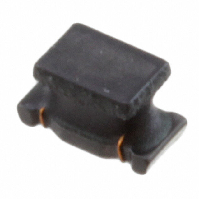
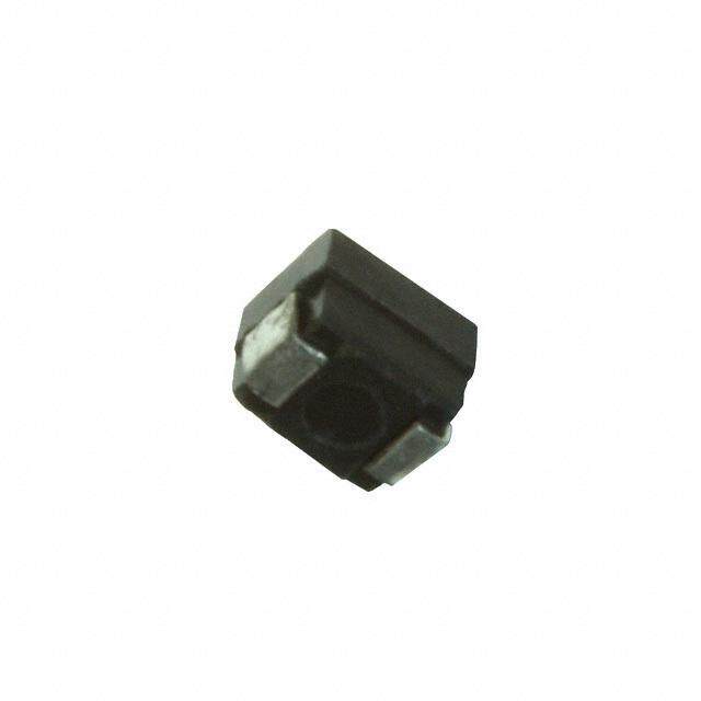
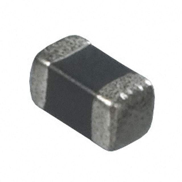
ICGOO电子元器件商城为您提供B82422A3331K100由EPCOS设计生产,在icgoo商城现货销售,并且可以通过原厂、代理商等渠道进行代购。 B82422A3331K100价格参考¥3.84-¥3.84。EPCOSB82422A3331K100封装/规格:固定值电感器, 330nH Unshielded Wirewound Inductor 200mA 1.3Ohm Max 2-SMD, J-Lead 。您可以下载B82422A3331K100参考资料、Datasheet数据手册功能说明书,资料中有B82422A3331K100 详细功能的应用电路图电压和使用方法及教程。
| 参数 | 数值 |
| 产品目录 | |
| DC电阻(DCR) | 1.3 欧姆最大 |
| 描述 | INDUCTOR .33UH 200MA 1210 10%固定电感器 330nH 200mA 10% 1210 SMD |
| 产品分类 | |
| 品牌 | EPCOS |
| 产品手册 | |
| 产品图片 |
|
| rohs | 符合RoHS无铅 / 符合限制有害物质指令(RoHS)规范要求 |
| 产品系列 | 固定电感器,EPCOS B82422A3331K100SIMID |
| 数据手册 | |
| 产品型号 | B82422A3331K100 |
| PCN设计/规格 | |
| Q最小值 | 22 |
| 不同频率时的Q值 | 22 @ 30MHz |
| 产品目录绘图 |
|
| 产品目录页面 | |
| 产品种类 | 固定电感器 |
| 供应商器件封装 | 1210 |
| 其它名称 | 495-1716-2 |
| 包装 | 带卷 (TR) |
| 商标 | EPCOS |
| 外壳宽度 | 2.5 mm |
| 外壳长度 | 3.2 mm |
| 外壳高度 | 2 mm |
| 大小/尺寸 | 0.126" 长 x 0.100" 宽 (3.20mm x 2.50mm) |
| 安装类型 | 表面贴装 |
| 容差 | 10 % |
| 封装 | Reel |
| 封装/外壳 | 1210(3225 公制) |
| 封装/箱体 | 1210 |
| 屏蔽 | 无屏蔽 |
| 工作温度 | - |
| 工作温度范围 | - 55 C to + 125 C |
| 工具箱 | /product-detail/zh/B82422X100/495-1679-ND/697354 |
| 工厂包装数量 | 2000 |
| 最大直流电流 | 200 mA |
| 最大直流电阻 | 1.3 Ohms |
| 材料-磁芯 | 陶瓷 |
| 标准包装 | 2,000 |
| 测试频率 | 30 MHz |
| 电感 | 330 nH |
| 电流-饱和值 | - |
| 端接类型 | SMD/SMT |
| 类型 | 绕线 |
| 系列 | SIMID |
| 自谐振频率 | 30 MHz |
| 芯体材料 | Ceramic |
| 频率-测试 | 1MHz |
| 频率-自谐振 | 580MHz |
| 额定电流 | 200mA |
| 高度-安装(最大值) | 0.083"(2.10mm) |

.jpg)


- 商务部:美国ITC正式对集成电路等产品启动337调查
- 曝三星4nm工艺存在良率问题 高通将骁龙8 Gen1或转产台积电
- 太阳诱电将投资9.5亿元在常州建新厂生产MLCC 预计2023年完工
- 英特尔发布欧洲新工厂建设计划 深化IDM 2.0 战略
- 台积电先进制程称霸业界 有大客户加持明年业绩稳了
- 达到5530亿美元!SIA预计今年全球半导体销售额将创下新高
- 英特尔拟将自动驾驶子公司Mobileye上市 估值或超500亿美元
- 三星加码芯片和SET,合并消费电子和移动部门,撤换高东真等 CEO
- 三星电子宣布重大人事变动 还合并消费电子和移动部门
- 海关总署:前11个月进口集成电路产品价值2.52万亿元 增长14.8%

PDF Datasheet 数据手册内容提取
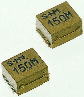
SMT inductors SIMID series, SIMID 1210-100 Series/Type: B82422A*100 Date: September 2019 aa~~íí~~==ppÜÜÉÉÉÉíí (cid:164)(cid:3)TDK Electronics AG 2019. Reproduction, publication and dissemination of this publication, enclosures hereto and the information contained therein without TDK Electronics’ prior express consent is prohibited.
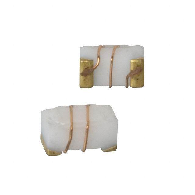
SMT inductors, SIMID series B82422A*100 SIMID 1210-100 Size 1210 (EIA) or 3225 (IEC) Rated inductance 0.0082 ... 100 μH Rated current 65 ... 800 mA Construction ■ Ceramic or ferrite core ■ Laser-welded winding ■ Flame-retardant molding Features ■ Temperature range up to +145 °C ■ High Q factor ■ High resonance frequency ■ Qualified to AEC-Q200 ■ Suitable for lead-free reflow soldering as referenced in JEDEC J-STD 020D ■ RoHS-compatible Applications ■ Filtering of supply voltages, coupling, decoupling ■ Antenna systems ■ Automotive electronics ■ Telecommunications ■ Consumer and data processing equipment ■ Industrial electronics Terminals ■ Base material CuSn6 ■ Layer composition Cu, Ag, Sn (lead-free)1) ■ Electro-plated Marking ■ Marking on component: Manufacturer, L value (in nH), tolerance of L value (coded), date of manufacture (YWWD) ■ Minimum data on reel: Manufacturer, ordering code, L value, quantity, date of packing Delivery mode and packing units ■ 8-mm blister tape, wound on 180-mm or 330-mm (cid:135) reel ■ Packing units: 180-mm reel: 2000 pcs./reel 330-mm reel: 8000 pcs./reel 1) Ni-barrier-plated terminals on request (B82422A*150). Please read Cautions and warnings and Important notes at the end of this document. 2 09/19
SMT inductors, SIMID series B82422A*100 SIMID 1210-100 Dimensional drawing and layout recommendation A B C D 2.7 1.15 2.1 4.4 Dimensions in mm Taping and packing Blister tape Reel Dimensions in mm 180 mm reel 330 mm reel A 180.0 +0/–3 330.0 (cid:114)2.0 C 13.0 +0.5/–0.2 13.0 +0.5/–0.2 N 60.0 (cid:114)1.0 75.0 +1.0/–3.0 W 8.4 +1.5/–0 8.4 +1.5/–0 1 W 14.4 max 14.4 max 2 Please read Cautions and warnings and Important notes at the end of this document. 3 09/19
SMT inductors, SIMID series B82422A*100 SIMID 1210-100 Technical data and measuring conditions Rated inductance L Measured with impedance analyzer Agilent 4294A or R equivalent at frequency f , 0.1 V, +20 °C L Q factor Q Measured with impedance analyzer Agilent 4294A or min equivalent at frequency f , +20 °C Q Rated temperature T +125 °C R Rated current I Maximum permissible DC with inductance decrease R (cid:39)L/L (cid:100)10% and temperature increase 0 of (cid:100) 20 K at rated temperature Self-resonance frequency f Measured with impedance analyzer Agilent E4991A / res,min network analyzer Agilent E8362B or equivalent at +20 °C DC resistance R Measured at +20 °C max Solderability (lead-free) Sn95.5Ag3.8Cu0.7: +(245 (cid:114)5) °C, (5 (cid:114)0.3) s Wetting of soldering area (cid:116) 90% (based on IEC 60068-2-58) Resistance to soldering heat +260 °C, 40 s (as referenced in JEDEC J-STD 020D) Climatic category 55/150/56 (to IEC 60068-1) Storage conditions Mounted: –55 °C … +150 °C Packaged: –25 °C … +40 °C, (cid:100) 75% RH Weight Approx. 50 mg Please read Cautions and warnings and Important notes at the end of this document. 4 09/19
SMT inductors, SIMID series B82422A*100 SIMID 1210-100 Characteristics and ordering codes L Tolerance f Q f I R f Ordering code1)2) R L min Q R max res, min ((cid:135) 180-mm reel) (cid:80)H MHz MHz mA (cid:58) MHz Core material: ceramic 0.0082 (cid:114)5% ^ J 10 20 100 800 0.08 4000 B82422A3829+100 0.010 (cid:114)10% ^ K 10 20 100 750 0.09 4000 B82422A3100+100 0.012 10 25 100 700 0.10 3500 B82422A3120+100 0.015 10 27 100 640 0.12 3000 B82422A3150+100 0.018 10 30 100 640 0.12 2500 B82422A3180+100 0.022 10 30 100 600 0.14 2500 B82422A3220+100 0.027 10 23 50 600 0.14 1850 B82422A3270+100 0.033 10 20 50 540 0.17 1700 B82422A3330+100 0.039 10 25 50 530 0.18 1450 B82422A3390+100 0.047 10 26 50 510 0.19 1350 B82422A3470+100 0.056 10 26 50 500 0.20 1200 B82422A3560+100 0.068 10 27 50 480 0.21 1150 B82422A3680+100 0.082 10 27 50 450 0.24 1050 B82422A3820+100 0.10 10 25 50 440 0.26 1000 B82422A3101+100 0.12 1 22 30 400 0.32 880 B82422A3121+100 0.15 1 25 30 390 0.33 850 B82422A3151+100 0.18 1 25 30 360 0.38 800 B82422A3181+100 0.22 1 25 30 280 0.64 700 B82422A3221+100 0.27 1 20 30 235 0.90 650 B82422A3271+100 0.33 1 22 30 200 1.3 580 B82422A3331+100 0.39 1 22 30 190 1.4 540 B82422A3391+100 0.47 1 22 30 150 2.2 480 B82422A3471+100 0.56 1 22 30 150 2.2 400 B82422A3561+100 0.68 1 22 30 145 2.4 280 B82422A3681+100 0.82 1 22 30 140 2.5 240 B82422A3821+100 Closer tolerances and special versions on request. Higher currents possible at temperatures <T on request. R Sample kit available. Ordering code: B82422X100 For more information refer to chapter “Sample kits”. 1) Replace the + by the code letter for the required inductance tolerance. For reel size (cid:135) 330 mm the last digit has to be an »8«. Example: B82422A3829K108 2) For Ni-barrier-plated terminals replace the last three digits “100” by “150” (reel 180 mm) or “158” (reel 330 mm). Please read Cautions and warnings and Important notes at the end of this document. 5 09/19
SMT inductors, SIMID series B82422A*100 SIMID 1210-100 Characteristics and ordering codes L Tolerance f Q f I R f Ordering code1)2) R L min Q R max res, min ((cid:135) 180-mm reel) (cid:80)H MHz MHz mA (cid:58) MHz Core material: ferrite 1.0 (cid:114)5% ^ J 1 20 7.96 380 0.34 320 B82422A1102+100 1.2 (cid:114)10% ^ K 1 20 7.96 370 0.37 300 B82422A1122+100 1.5 1 20 7.96 340 0.50 270 B82422A1152+100 1.8 1 25 7.96 290 0.60 250 B82422A1182+100 2.2 1 25 7.96 270 0.75 125 B82422A1222+100 2.7 1 25 7.96 240 0.88 110 B82422A1272+100 3.3 1 27 7.96 200 1.20 110 B82422A1332+100 3.9 1 27 7.96 190 1.40 110 B82422A1392+100 4.7 1 27 7.96 150 2.20 110 B82422A1472+100 5.6 1 27 7.96 140 2.60 100 B82422A1562+100 6.8 1 27 7.96 135 2.80 90 B82422A1682+100 8.2 1 27 7.96 130 3.00 90 B82422A1822+100 10 1 27 2.52 180 1.60 25 B82422A1103+100 12 0.1 27 2.52 175 1.65 23 B82422A1123+100 15 0.1 27 2.52 165 1.85 20 B82422A1153+100 18 0.1 27 2.52 155 2.00 17 B82422A1183+100 22 0.1 27 2.52 140 2.65 16 B82422A1223+100 27 0.1 27 2.52 120 3.70 15 B82422A1273+100 33 0.1 27 2.52 105 4.50 13 B82422A1333+100 39 0.1 27 2.52 90 6.30 12 B82422A1393+100 47 0.1 27 2.52 85 7.00 11 B82422A1473+100 56 0.1 27 2.52 85 6.75 9 B82422A1563+100 68 0.1 27 2.52 80 7.70 9 B82422A1683+100 82 0.1 27 2.52 70 10.0 8 B82422A1823+100 100 0.1 27 2.52 65 11.5 7 B82422A1104+100 Closer tolerances and special versions on request. Higher currents possible at temperatures <T on request. R Sample kit available. Ordering code: B82422X100 For more information refer to chapter “Sample kits”. 1) Replace the + by the code letter for the required inductance tolerance. For reel size (cid:135) 330 mm the last digit has to be an »8«. Example: B82422A1104K108 2) For Ni-barrier-plated terminals replace the last three digits “100” by “150” (reel 180 mm) or “158” (reel 330 mm). Please read Cautions and warnings and Important notes at the end of this document. 6 09/19
SMT inductors, SIMID series B82422A*100 SIMID 1210-100 Impedance |Z| versus frequency f Inductance L versus DC load current I DC measured with impedance analyzer measured with LCR meter Agilent 4285A, Agilent E4991A, typical values at +20 °C typical values at +20 °C Q factor versus frequency f Current derating I /I op R measured with impedance analyzer Agilent versus ambient temperature T A 4294A/E4991A, typical values at +20 °C (rated temperature T = +125 °C) R Please read Cautions and warnings and Important notes at the end of this document. 7 09/19
Cautions and warnings ■ Please note the recommendations in our Inductors data book (latest edition) and in the data sheets. – Particular attention should be paid to the derating curves given there. – The soldering conditions should also be observed. Temperatures quoted in relation to wave soldering refer to the pin, not the housing. ■ If the components are to be washed varnished it is necessary to check whether the washing varnish agent that is used has a negative effect on the wire insulation, any plastics that are used, or on glued joints. In particular, it is possible for washing varnish agent residues to have a negative effect in the long-term on wire insulation. Washing processes may damage the product due to the possible static or cyclic mechanical loads (e.g. ultrasonic cleaning). They may cause cracks to develop on the product and its parts, which might lead to reduced reliability or lifetime. ■ The following points must be observed if the components are potted in customer applications: – Many potting materials shrink as they harden. They therefore exert a pressure on the plastic housing or core. This pressure can have a deleterious effect on electrical properties, and in extreme cases can damage the core or plastic housing mechanically. – It is necessary to check whether the potting material used attacks or destroys the wire, wire insulation, plastics or glue. – The effect of the potting material can change the high-frequency behaviour of the components. – Many coating materials have a negative effect (chemically and mechanically) on the winding wires, insulation materials and connecting points. Customers are always obligated to determine whether and to what extent their coating materials influence the component. Customers are responsible and bear all risk for the use of the coating material. TDK Electronics does not assume any liability for failures of our components that are caused by the coating material. ■ Ceramics / ferrites are sensitive to direct impact. This can cause the core material to flake, or lead to breakage of the core. ■ Even for customer-specific products, conclusive validation of the component in the circuit can only be carried out by the customer. Display of ordering codes for TDK Electronics products The ordering code for one and the same product can be represented differently in data sheets, data books, other publications, on the company website, or in order-related documents such as shipping notes, order confirmations and product labels. The varying representations of the ordering codes are due to different processes employed and do not affect the specifications of the respective products. Detailed information can be found on the Internet under www.tdk-electronics.tdk.com/orderingcodes. Please read Cautions and warnings and Important notes at the end of this document. 8 09/19
Important notes The following applies to all products named in this publication: 1. Some parts of this publication contain statements about the suitability of our products for certain areas of application. These statements are based on our knowledge of typical require- ments that are often placed on our products in the areas of application concerned. We never- theless expressly point out that such statements cannot be regarded as binding statements about the suitability of our products for a particular customer application. As a rule, we are either unfamiliar with individual customer applications or less familiar with them than the cus- tomers themselves. For these reasons, it is always ultimately incumbent on the customer to check and decide whether a product with the properties described in the product specification is suitable for use in a particular customer application. 2. We also point out that in individual cases, a malfunction of electronic components or fail- ure before the end of their usual service life cannot be completely ruled out in the current state of the art, even if they are operated as specified. In customer applications requiring a very high level of operational safety and especially in customer applications in which the mal- function or failure of an electronic component could endanger human life or health (e.g. in acci- dent prevention or life-saving systems), it must therefore be ensured by means of suitable de- sign of the customer application or other action taken by the customer (e.g. installation of pro- tective circuitry or redundancy) that no injury or damage is sustained by third parties in the event of malfunction or failure of an electronic component. 3. The warnings, cautions and product-specific notes must be observed. 4. In order to satisfy certain technical requirements, some of the products described in this pub- lication may contain substances subject to restrictions in certain jurisdictions (e.g. be- cause they are classed as hazardous). Useful information on this will be found in our Material Data Sheets on the Internet (www.tdk-electronics.tdk.com/material). Should you have any more detailed questions, please contact our sales offices. 5. We constantly strive to improve our products. Consequently, the products described in this publication may change from time to time. The same is true of the corresponding product specifications. Please check therefore to what extent product descriptions and specifications contained in this publication are still applicable before or when you place an order. We also reserve the right to discontinue production and delivery of products. Consequent- ly, we cannot guarantee that all products named in this publication will always be available. The aforementioned does not apply in the case of individual agreements deviating from the foregoing for customer-specific products. 6. Unless otherwise agreed in individual contracts, all orders are subject to our General Terms and Conditions of Supply. 9 09/19
Important notes 7. Our manufacturing sites serving the automotive business apply the IATF 16949 standard. The IATF certifications confirm our compliance with requirements regarding the quality manage- ment system in the automotive industry. Referring to customer requirements and customer spe- cific requirements (“CSR”) TDK always has and will continue to have the policy of respecting in- dividual agreements. Even if IATF 16949 may appear to support the acceptance of unilateral re- quirements, we hereby like to emphasize that only requirements mutually agreed upon can and will be implemented in our Quality Management System. For clarification purposes we like to point out that obligations from IATF 16949 shall only become legally binding if individually agreed upon. 8. The trade names EPCOS, CeraCharge, CeraDiode, CeraLink, CeraPad, CeraPlas, CSMP, CTVS, DeltaCap, DigiSiMic, ExoCore, FilterCap, FormFit, LeaXield, MiniBlue, MiniCell, MKD, MKK, MotorCap, PCC, PhaseCap, PhaseCube, PhaseMod, PhiCap, PowerHap, PQSine, PQvar, SIFERRIT, SIFI, SIKOREL, SilverCap, SIMDAD, SiMic, SIMID, SineFormer, SIOV, ThermoFuse, WindCap are trademarks registered or pending in Europe and in other coun- tries. Further information will be found on the Internet at www.tdk-electronics.tdk.com/trademarks. Release 2018-10 10 09/19