ICGOO在线商城 > 电路保护 > TVS - 变阻器,MOV > B72210S2301K101

 Datasheet下载
- 型号: B72210S2301K101
- 制造商: EPCOS
- 库位|库存: xxxx|xxxx
- 要求:
| 数量阶梯 | 香港交货 | 国内含税 |
| +xxxx | $xxxx | ¥xxxx |
查看当月历史价格
查看今年历史价格
B72210S2301K101产品简介:
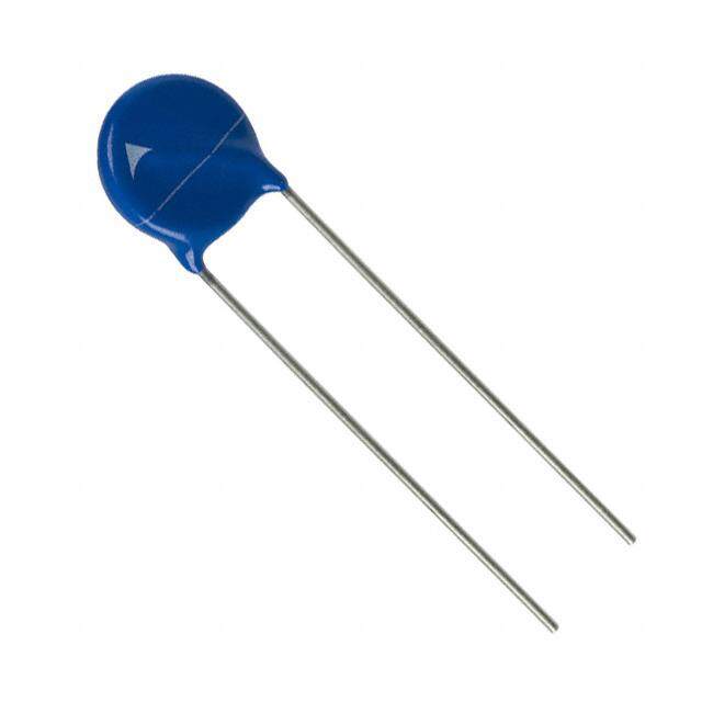
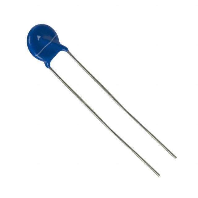
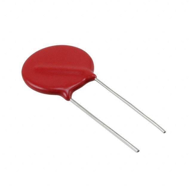
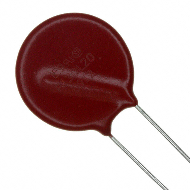
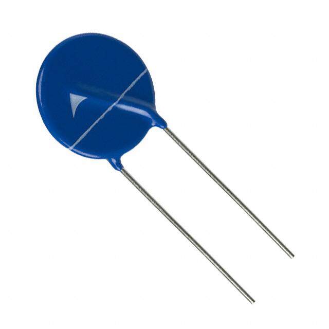
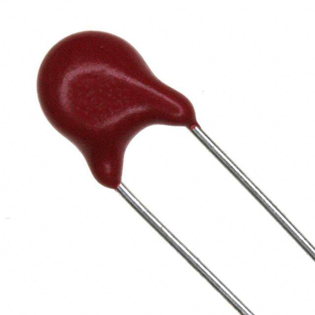
ICGOO电子元器件商城为您提供B72210S2301K101由EPCOS设计生产,在icgoo商城现货销售,并且可以通过原厂、代理商等渠道进行代购。 B72210S2301K101价格参考。EPCOSB72210S2301K101封装/规格:TVS - 变阻器,MOV, 470V 3.5kA Varistor 1 Circuit Through Hole Disc 10mm。您可以下载B72210S2301K101参考资料、Datasheet数据手册功能说明书,资料中有B72210S2301K101 详细功能的应用电路图电压和使用方法及教程。
| 参数 | 数值 |
| 品牌 | EPCOS |
| 产品目录 | 无源元件 |
| 描述 | 压敏电阻 Varistor S10K300E2 |
| 产品分类 | 压敏电阻 |
| 产品手册 | |
| 产品图片 |
|
| rohs | 符合RoHS |
| 产品系列 | EPCOS B72210S2301K101 |
| 产品型号 | B72210S2301K101 |
| 产品种类 | 压敏电阻 |
| 商标 | EPCOS |
| 外壳直径 | 12 mm |
| 安装 | Radial |
| 封装 | Bulk |
| 尺寸 | 12 mm Dia. x 25 mm L |
| 峰值浪涌电流 | 3.5 kA |
| 工作温度范围 | - 40 C to + 85 C |
| 工厂包装数量 | 500 |
| 引线间隔 | 7.5 mm |
| 浪涌能量额定值 | 60 J |
| 电压额定值AC | 300 V |
| 电压额定值DC | 385 V |
| 电容 | 180 pF |
| 系列 | AdvanceD |


- 商务部:美国ITC正式对集成电路等产品启动337调查
- 曝三星4nm工艺存在良率问题 高通将骁龙8 Gen1或转产台积电
- 太阳诱电将投资9.5亿元在常州建新厂生产MLCC 预计2023年完工
- 英特尔发布欧洲新工厂建设计划 深化IDM 2.0 战略
- 台积电先进制程称霸业界 有大客户加持明年业绩稳了
- 达到5530亿美元!SIA预计今年全球半导体销售额将创下新高
- 英特尔拟将自动驾驶子公司Mobileye上市 估值或超500亿美元
- 三星加码芯片和SET,合并消费电子和移动部门,撤换高东真等 CEO
- 三星电子宣布重大人事变动 还合并消费电子和移动部门
- 海关总署:前11个月进口集成电路产品价值2.52万亿元 增长14.8%

PDF Datasheet 数据手册内容提取
SIOV metal oxide varistors Leaded varistors, AdvanceD series Series/Type: B722* Date: January2018 ©EPCOSAG2018.Reproduction,publicationanddisseminationofthispublication,enclosuresheretoandthe informationcontainedthereinwithoutEPCOS'priorexpressconsentisprohibited. EPCOSAGisaTDKGroupCompany.
Leadedvaristors B722* AdvanceDseries Construction Roundvaristorelement,leaded Coating:epoxyresin,flame-retardanttoUL94V-0 Terminals:tinnedwire Features High-energyAdvanceDseriesE2 Highsurgecurrentratingsupto10kA Highenergyratingsupto440J Wideoperatingvoltagerange130…680V RMS PSpicemodels Approvals UL CSA VDE CQCS05/07(K11…K460),S10/S14(K11…K680),S20(K11…K1000) IEC Deliverymode Bulk(standard),tapedversionsonreelorinAmmopackuponrequest. Forfurtherdetailsrefertochapter"Taping,packagingandleadconfiguration"forleaded varistors. Generaltechnicaldata Climaticcategory toIEC60068-1 40/105/56 Operatingtemperature toIEC61051 (cid:4)40...+105 (cid:176) C Storagetemperature (cid:4)40...+125 (cid:176) C Electricstrength toIEC61051 ‡ 2.5 kV RMS Insulationresistance toIEC61051 ‡ 100 MW PleasereadCautionsandwarningsand Page2of35 Importantnotesattheendofthisdocument.
Leadedvaristors B722* AdvanceDseries Electricalspecificationsandorderingcodes Maximumratings(T =105(cid:176) C) A Orderingcode Type VRMS VDC imax In1) Wmax Pmax (untaped) (8/20µs) (8/20µs) (2ms) SIOV- 1time 15times V V A A J W V =130V RMS B72205S2131K101 S05K130E2 130 170 800 150 6.0 0.10 B72207S2131K101 S07K130E2 130 170 1750 500 12.5 0.25 B72210S2131K101 S10K130E2 130 170 3500 1500 25.0 0.40 B72214S2131K101 S14K130E2 130 170 6000 3000 50.0 0.60 B72220S2131K101 S20K130E2 130 170 10000 3000 100.0 1.00 V =140V RMS B72205S2141K101 S05K140E2 140 180 800 150 6.5 0.10 B72207S2141K101 S07K140E2 140 180 1750 500 13.5 0.25 B72210S2141K101 S10K140E2 140 180 3500 1500 27.5 0.40 B72214S2141K101 S14K140E2 140 180 6000 3000 55.0 0.60 B72220S2141K101 S20K140E2 140 180 10000 3000 110.0 1.00 V =150V RMS B72205S2151K101 S05K150E2 150 200 800 150 7.5 0.10 B72207S2151K101 S07K150E2 150 200 1750 500 15.0 0.25 B72210S2151K101 S10K150E2 150 200 3500 1500 30.0 0.40 B72214S2151K101 S14K150E2 150 200 6000 3000 60.0 0.60 B72220S2151K101 S20K150E2 150 200 10000 3000 120.0 1.00 V =175V RMS B72205S2171K101 S05K175E2 175 225 800 150 8.0 0.10 B72207S2171K101 S07K175E2 175 225 1750 500 17.0 0.25 B72210S2171K101 S10K175E2 175 225 3500 1500 35.0 0.40 B72214S2171K101 S14K175E2 175 225 6000 3000 70.0 0.60 B72220S2171K101 S20K175E2 175 225 10000 3000 135.0 1.00 V =210V RMS B72205S2211K101 S05K210E2 210 270 800 150 9.5 0.10 B72207S2211K101 S07K210E2 210 270 1750 500 20.0 0.25 B72210S2211K101 S10K210E2 210 270 3500 1500 42.0 0.40 B72214S2211K101 S14K210E2 210 270 6000 3000 80.0 0.60 B72220S2211K101 S20K210E2 210 270 10000 3000 160.0 1.00 V =230V RMS B72205S2231K101 S05K230E2 230 300 800 150 11.0 0.10 B72207S2231K101 S07K230E2 230 300 1750 500 23.0 0.25 B72210S2231K101 S10K230E2 230 300 3500 1500 45.0 0.40 B72214S2231K101 S14K230E2 230 300 6000 3000 90.0 0.60 B72220S2231K101 S20K230E2 230 300 10000 3000 180.0 1.00 1)Note:NominaldischargecurrentI accordingtoUL1449,4thedition. n PleasereadCautionsandwarningsand Page3of35 Importantnotesattheendofthisdocument.
Leadedvaristors B722* AdvanceDseries Characteristics(T =25(cid:176) C) A Orderingcode Vv D Vv vc,max ic Ctyp (1mA) (1mA) (i) (1kHz) c V % V A pF V =130V RMS B72205S2131K101 205 – 10 340 5.0 135 B72207S2131K101 205 – 10 340 10.0 245 B72210S2131K101 205 – 10 340 25.0 500 B72214S2131K101 205 – 10 340 50.0 880 B72220S2131K101 205 – 10 340 100.0 1850 V =140V RMS B72205S2141K101 220 – 10 360 5.0 125 B72207S2141K101 220 – 10 360 10.0 230 B72210S2141K101 220 – 10 360 25.0 470 B72214S2141K101 220 – 10 360 50.0 820 B72220S2141K101 220 – 10 360 100.0 1700 V =150V RMS B72205S2151K101 240 – 10 395 5.0 115 B72207S2151K101 240 – 10 395 10.0 210 B72210S2151K101 240 – 10 395 25.0 430 B72214S2151K101 240 – 10 395 50.0 750 B72220S2151K101 240 – 10 395 100.0 1550 V =175V RMS B72205S2171K101 270 – 10 455 5.0 100 B72207S2171K101 270 – 10 455 10.0 190 B72210S2171K101 270 – 10 455 25.0 380 B72214S2171K101 270 – 10 455 50.0 670 B72220S2171K101 270 – 10 455 100.0 1350 V =210V RMS B72205S2211K101 330 – 10 545 5.0 75 B72207S2211K101 330 – 10 545 10.0 140 B72210S2211K101 330 – 10 545 25.0 290 B72214S2211K101 330 – 10 545 50.0 580 B72220S2211K101 330 – 10 545 100.0 1100 V =230V RMS B72205S2231K101 360 – 10 595 5.0 70 B72207S2231K101 360 – 10 595 10.0 130 B72210S2231K101 360 – 10 595 25.0 265 B72214S2231K101 360 – 10 595 50.0 530 B72220S2231K101 360 – 10 595 100.0 1000 PleasereadCautionsandwarningsand Page4of35 Importantnotesattheendofthisdocument.
Leadedvaristors B722* AdvanceDseries Electricalspecificationsandorderingcodes Maximumratings(T =105(cid:176) C) A Orderingcode Type VRMS VDC imax In1) Wmax Pmax (untaped) (8/20µs) (8/20µs) (2ms) SIOV- 1time 15times V V A A J W V =250V RMS B72205S2251K101 S05K250E2 250 320 800 150 12.0 0.10 B72207S2251K101 S07K250E2 250 320 1750 500 25.0 0.25 B72210S2251K101 S10K250E2 250 320 3500 1500 50.0 0.40 B72214S2251K101 S14K250E2 250 320 6000 3000 100.0 0.60 B72220S2251K101 S20K250E2 250 320 10000 3000 195.0 1.00 V =275V RMS B72205S2271K101 S05K275E2 275 350 800 150 13.5 0.10 B72207S2271K101 S07K275E2 275 350 1750 500 27.5 0.25 B72210S2271K101 S10K275E2 275 350 3500 1500 55.0 0.40 B72214S2271K101 S14K275E2 275 350 6000 3000 110.0 0.60 B72220S2271K101 S20K275E2 275 350 10000 3000 215.0 1.00 V =300V RMS B72205S2301K101 S05K300E2 300 385 800 150 15.0 0.10 B72207S2301K101 S07K300E2 300 385 1750 500 30.0 0.25 B72210S2301K101 S10K300E2 300 385 3500 1500 60.0 0.40 B72214S2301K101 S14K300E2 300 385 6000 3000 125.0 0.60 B72220S2301K101 S20K300E2 300 385 10000 3000 250.0 1.00 V =320V RMS B72207S2321K101 S07K320E2 320 420 1750 500 32.0 0.25 B72210S2321K101 S10K320E2 320 420 3500 1500 67.0 0.40 B72214S2321K101 S14K320E2 320 420 6000 3000 136.0 0.60 B72220S2321K101 S20K320E2 320 420 10000 3000 273.0 1.00 V =350V RMS B72210S2351K101 S10K350E2 350 460 3500 1500 67.0 0.40 B72214S2351K101 S14K350E2 350 460 5000 3000 136.0 0.60 B72220S2351K101 S20K350E2 350 460 10000 3000 273.0 1.00 V =385V RMS B72210S2381K101 S10K385E2 385 505 3500 1500 67.0 0.40 B72214S2381K101 S14K385E2 385 505 5000 3000 136.0 0.60 B72220S2381K101 S20K385E2 385 505 10000 3000 273.0 1.00 1)Note:NominaldischargecurrentI accordingtoUL1449,4thedition. n PleasereadCautionsandwarningsand Page5of35 Importantnotesattheendofthisdocument.
Leadedvaristors B722* AdvanceDseries Characteristics(T =25(cid:176) C) A Orderingcode Vv D Vv vc,max ic Ctyp (1mA) (1mA) (i) (1kHz) c V % V A pF V =250V RMS B72205S2251K101 390 – 10 650 5.0 65 B72207S2251K101 390 – 10 650 10.0 120 B72210S2251K101 390 – 10 650 25.0 245 B72214S2251K101 390 – 10 650 50.0 490 B72220S2251K101 390 – 10 650 100.0 940 V =275V RMS B72205S2271K101 430 – 10 710 5.0 60 B72207S2271K101 430 – 10 710 10.0 110 B72210S2271K101 430 – 10 710 25.0 220 B72214S2271K101 430 – 10 710 50.0 440 B72220S2271K101 430 – 10 710 100.0 850 V =300V RMS B72205S2301K101 470 – 10 775 5.0 55 B72207S2301K101 470 – 10 775 10.0 100 B72210S2301K101 470 – 10 775 25.0 200 B72214S2301K101 470 – 10 775 50.0 400 B72220S2301K101 470 – 10 775 100.0 780 V =320V RMS B72207S2321K101 510 – 10 840 10.0 90 B72210S2321K101 510 – 10 840 25.0 185 B72214S2321K101 510 – 10 840 50.0 370 B72220S2321K101 510 – 10 840 100.0 720 V =350V RMS B72210S2351K101 560 – 10 910 25.0 160 B72214S2351K101 560 – 10 910 50.0 350 B72220S2351K101 560 – 10 910 100.0 660 V =385V RMS B72210S2381K101 620 – 10 1025 25.0 175 B72214S2381K101 620 – 10 1025 50.0 315 B72220S2381K101 620 – 10 1025 100.0 600 PleasereadCautionsandwarningsand Page6of35 Importantnotesattheendofthisdocument.
Leadedvaristors B722* AdvanceDseries Electricalspecificationsandorderingcodes Maximumratings(T =105(cid:176) C) A Orderingcode Type VRMS VDC imax In1) Wmax Pmax (untaped) (8/20µs) (8/20µs) (2ms) SIOV- 1time 15times V V A A J W V =420V RMS B72210S2421K101 S10K420E2 420 560 3500 1500 67.0 0.40 B72214S2421K101 S14K420E2 420 560 5000 3000 136.0 0.60 B72220S2421K101 S20K420E2 420 560 10000 3000 273.0 1.00 V =460V RMS B72210S2461K101 S10K460E2 460 615 3500 1500 70.0 0.40 B72214S2461K101 S14K460E2 460 615 5000 3000 150.0 0.60 B72220S2461K101 S20K460E2 460 615 10000 3000 300.0 1.00 V =510V RMS B72210S2511K101 S10K510E2 510 670 3500 1500 80.0 0.40 B72214S2511K101 S14K510E2 510 670 5000 3000 165.0 0.60 B72220S2511K101 S20K510E2 510 670 10000 3000 325.0 1.00 V =550V RMS B72210S2551K101 S10K550E2 550 745 3500 1500 90.0 0.40 B72214S2551K101 S14K550E2 550 745 5000 3000 180.0 0.60 B72220S2551K101 S20K550E2 550 745 10000 3000 360.0 1.00 V =625V RMS B72210S2621K101 S10K625E2 625 825 3500 1500 100.0 0.40 B72214S2621K101 S14K625E2 625 825 5000 3000 200.0 0.60 B72220S2621K101 S20K625E2 625 825 10000 3000 400.0 1.00 V =680V RMS B72210S2681K101 S10K680E2 680 895 3500 1500 110.0 0.40 B72214S2681K101 S14K680E2 680 895 5000 3000 220.0 0.60 B72220S2681K101 S20K680E2 680 895 10000 3000 440.0 1.00 1)Note:NominaldischargecurrentI accordingtoUL1449,4thedition. n PleasereadCautionsandwarningsand Page7of35 Importantnotesattheendofthisdocument.
Leadedvaristors B722* AdvanceDseries Characteristics(T =25(cid:176) C) A Orderingcode Vv D Vv vc,max ic Ctyp (1mA) (1mA) (i) (1kHz) c V % V A pF V =420V RMS B72210S2421K101 680 – 10 1120 25.0 165 B72214S2421K101 680 – 10 1120 50.0 290 B72220S2421K101 680 – 10 1120 100.0 550 V =460V RMS B72210S2461K101 750 – 10 1240 25.0 150 B72214S2461K101 750 – 10 1240 50.0 260 B72220S2461K101 750 – 10 1240 100.0 500 V =510V RMS B72210S2511K101 820 – 10 1355 25.0 140 B72214S2511K101 820 – 10 1355 50.0 240 B72220S2511K101 820 – 10 1355 100.0 460 V =550V RMS B72210S2551K101 910 – 10 1500 25.0 120 B72214S2551K101 910 – 10 1500 50.0 215 B72220S2551K101 910 – 10 1500 100.0 410 V =625V RMS B72210S2621K101 1000 – 10 1650 25.0 110 B72214S2621K101 1000 – 10 1650 50.0 200 B72220S2621K101 1000 – 10 1650 100.0 380 V =680V RMS B72210S2681K101 1100 – 10 1815 25.0 100 B72214S2681K101 1100 – 10 1815 50.0 180 B72220S2681K101 1100 – 10 1815 100.0 340 PleasereadCautionsandwarningsand Page8of35 Importantnotesattheendofthisdocument.
Leadedvaristors B722* AdvanceDseries Dimensionaldrawings Weight Nominaldiameter V Weight RMS mm V g 5 130...300 0.4...0.5 7 130...320 0.6...0.8 10 130...680 1.2...2.8 14 130...680 1.8...4.8 20 130...680 3.3...9.6 Theweightofvaristorsinbetweenthesevoltage classescanbeinterpolated. Dimensions Orderingcode [e]– 1 a(typical) wmax thmax hmax lmin d– 0.05 mm mm mm mm mm mm mm V =130V RMS B72205S2131K101 5.0 1.6 7.0 3.9 8.5 25.0 0.6 B72207S2131K101 5.0 1.6 9.0 3.9 11.0 25.0 0.6 B72210S2131K101 7.5 1.8 12.0 4.5 14.5 25.0 0.8 B72214S2131K101 7.5 1.9 15.5 4.6 18.5 25.0 0.8 B72220S2131K101 10.0 2.0 21.5 5.0 25.5 25.0 1.0 V =140V RMS B72205S2141K101 5.0 1.7 7.0 4.0 8.5 25.0 0.6 B72207S2141K101 5.0 1.7 9.0 4.0 11.0 25.0 0.6 B72210S2141K101 7.5 1.9 12.0 4.6 14.5 25.0 0.8 B72214S2141K101 7.5 2.0 15.5 4.7 18.5 25.0 0.8 B72220S2141K101 10.0 2.1 21.5 5.1 25.5 25.0 1.0 V =150V RMS B72205S2151K101 5.0 1.8 7.0 4.1 8.5 25.0 0.6 B72207S2151K101 5.0 1.8 9.0 4.1 11.0 25.0 0.6 B72210S2151K101 7.5 2.0 12.0 4.7 14.5 25.0 0.8 B72214S2151K101 7.5 2.1 15.5 4.8 18.5 25.0 0.8 B72220S2151K101 10.0 2.2 21.5 5.2 25.5 25.0 1.0 V =175V RMS B72205S2171K101 5.0 2.0 7.0 4.3 8.5 25.0 0.6 B72207S2171K101 5.0 2.0 9.0 4.3 11.0 25.0 0.6 B72210S2171K101 7.5 2.2 12.0 4.9 14.5 25.0 0.8 B72214S2171K101 7.5 2.2 15.5 4.9 18.5 25.0 0.8 B72220S2171K101 10.0 2.3 21.5 5.3 25.5 25.0 1.0 PleasereadCautionsandwarningsand Page9of35 Importantnotesattheendofthisdocument.
Leadedvaristors B722* AdvanceDseries Orderingcode [e]– 1 a(typical) wmax thmax hmax lmin d– 0.05 mm mm mm mm mm mm mm V =210V RMS B72205S2211K101 5.0 1.7 7.0 4.2 8.5 25.0 0.6 B72207S2211K101 5.0 1.7 9.0 4.2 11.0 25.0 0.6 B72210S2211K101 7.5 1.9 12.0 5.0 14.5 25.0 0.8 B72214S2211K101 7.5 1.9 15.5 5.0 18.5 25.0 0.8 B72220S2211K101 10.0 2.2 21.5 5.4 25.5 25.0 1.0 V =230V RMS B72205S2231K101 5.0 1.5 7.0 4.4 8.5 25.0 0.6 B72207S2231K101 5.0 1.5 9.0 4.4 11.0 25.0 0.6 B72210S2231K101 7.5 1.7 12.0 5.0 14.5 25.0 0.8 B72214S2231K101 7.5 1.7 15.5 5.1 18.5 25.0 0.8 B72220S2231K101 10.0 1.8 21.5 5.5 25.5 25.0 1.0 V =250V RMS B72205S2251K101 5.0 1.5 7.0 4.5 8.5 25.0 0.6 B72207S2251K101 5.0 1.5 9.0 4.5 11.0 25.0 0.6 B72210S2251K101 7.5 1.7 12.0 5.2 14.5 25.0 0.8 B72214S2251K101 7.5 1.7 15.5 5.2 18.5 25.0 0.8 B72220S2251K101 10.0 1.9 21.5 5.7 25.5 25.0 1.0 V =275V RMS B72205S2271K101 5.0 1.6 7.0 4.6 8.5 25.0 0.6 B72207S2271K101 5.0 1.6 9.0 4.6 11.0 25.0 0.6 B72210S2271K101 7.5 1.8 12.0 5.4 14.5 25.0 0.8 B72214S2271K101 7.5 1.8 15.5 5.4 18.5 25.0 0.8 B72220S2271K101 10.0 2.0 21.5 5.8 25.5 25.0 1.0 V =300V RMS B72205S2301K101 5.0 1.7 7.0 4.7 8.5 25.0 0.6 B72207S2301K101 5.0 1.7 9.0 4.7 11.0 25.0 0.6 B72210S2301K101 7.5 1.9 12.0 5.6 14.5 25.0 0.8 B72214S2301K101 7.5 1.9 15.5 5.6 18.5 25.0 0.8 B72220S2301K101 10.0 2.1 21.5 6.1 25.5 25.0 1.0 V =320V RMS B72207S2321K101 5.0 1.9 9.0 4.6 11.0 25.0 0.6 B72210S2321K101 7.5 2.1 12.0 5.8 15.0 25.0 0.8 B72214S2321K101 7.5 2.1 15.5 5.8 19.0 25.0 0.8 B72220S2321K101 10.0 2.3 21.5 6.2 25.5 25.0 1.0 PleasereadCautionsandwarningsand Page10of35 Importantnotesattheendofthisdocument.
Leadedvaristors B722* AdvanceDseries Orderingcode [e]– 1 a(typical) wmax thmax hmax lmin d– 0.05 mm mm mm mm mm mm mm V =350V RMS B72210S2351K101 7.5 2.2 12.0 6.5 15.0 25.0 0.8 B72214S2351K101 7.5 2.2 15.5 6.5 19.0 25.0 0.8 B72220S2351K101 10.0 2.4 21.5 7.0 25.5 25.0 1.0 V =385V RMS B72210S2381K101 7.5 2.4 12.0 7.1 15.0 25.0 0.8 B72214S2381K101 7.5 2.4 15.5 7.1 19.0 25.0 0.8 B72220S2381K101 10.0 2.5 21.5 7.6 26.0 25.0 1.0 V =420V RMS B72210S2421K101 7.5 2.6 12.0 7.4 15.0 25.0 0.8 B72214S2421K101 7.5 2.6 15.5 7.5 19.0 25.0 0.8 B72220S2421K101 10.0 2.7 21.5 7.9 26.0 25.0 1.0 V =460V RMS B72210S2461K101 7.5 2.8 12.0 7.7 15.0 25.0 0.8 B72214S2461K101 7.5 2.8 15.5 7.8 19.0 25.0 0.8 B72220S2461K101 10.0 3.0 21.5 8.2 26.0 25.0 1.0 V =510V RMS B72210S2511K101 7.5 3.1 12.0 8.0 15.0 25.0 0.8 B72214S2511K101 7.5 3.1 15.5 8.1 19.0 25.0 0.8 B72220S2511K101 10.0 3.2 21.5 8.6 26.0 25.0 1.0 V =550V RMS B72210S2551K101 7.5 3.4 12.0 8.4 15.0 25.0 0.8 B72214S2551K101 7.5 3.4 15.5 8.5 19.0 25.0 0.8 B72220S2551K101 10.0 3.6 21.5 9.0 26.0 25.0 1.0 V =625V RMS B72210S2621K101 7.5 3.7 12.0 8.8 15.0 25.0 0.8 B72214S2621K101 7.5 3.7 15.5 8.9 19.0 25.0 0.8 B72220S2621K101 10.0 3.9 21.5 9.4 26.0 25.0 1.0 V =680V RMS B72210S2681K101 7.5 4.1 12.0 9.2 15.0 25.0 0.8 B72214S2681K101 7.5 4.1 15.5 9.3 19.0 25.0 0.8 B72220S2681K101 10.0 4.2 21.5 9.8 26.0 25.0 1.0 PleasereadCautionsandwarningsand Page11of35 Importantnotesattheendofthisdocument.
Leadedvaristors B722* AdvanceDseries Reliabilitydata Test Testmethods/conditions Requirement Varistorvoltage Thevoltagebetweentwoterminalswith Tomeetthespecifiedvalue thespecifiedmeasuringcurrentapplied iscalledV (1mA @0.2...2s). V DC Clampingvoltage Themaximumvoltagebetweentwo Tomeetthespecifiedvalue terminalswiththespecifiedstandard impulsecurrent(8/20µs)applied. Enduranceatupper 1000hatUCT |D V/V(1mA)|£ 10% categorytemperature Afterhavingcontinuouslyappliedthe maximumallowableACvoltageatUCT – 2(cid:176) Cfor1000h,thespecimenshallbe storedatroomtemperatureandnormal humidityfor1to2h. Thereafter,thechangeofV shallbe V measured. Surgecurrentderating, 10surgecurrents(8/20m s),unipolar, |D V/V(1mA)|£ 10% 8/20m s interval30s,amplitudecorresponding (measuredindirectionof toderatingcurvefor10impulsesat surgecurrent) 20m s Novisibledamage Surgecurrentderating, 10surgecurrents(2ms),unipolar, |D V/V(1mA)|£ 10% 2ms interval120s,amplitudecorresponding (measuredindirectionof toderatingcurvefor10impulsesat surgecurrent) 2ms Novisibledamage Electricstrength IEC61051-1,test4.9.2 Nobreakdown Metalballsmethod,2500V ,60s RMS Thevaristorisplacedinacontainer holding1.6– 0.2mmdiametermetal ballssuchthatonlytheterminationsof thevaristorareprotruding. Thespecifiedvoltageshallbeapplied betweenbothterminalsofthespecimen connectedtogetherandtheelectrode insertedbetweenthemetalballs. PleasereadCautionsandwarningsand Page12of35 Importantnotesattheendofthisdocument.
Leadedvaristors B722* AdvanceDseries Test Testmethods/conditions Requirement Climaticsequence Thespecimenshallbesubjectedto: |D V/V(1mA)|£ 10% a)dryheatatUCT,16h,IEC R ‡ 100MW ins 60068-2-2,testBa b)dampheat,1stcycle: 55(cid:176) C,93%r.H.,24h,IEC 60068-2-30,testDb c)cold,LCT,2h,IEC60068-2-1,test Aa d)dampheat,additional5cycles: 55(cid:176) C/25(cid:176) C,93%r.H.,24h/cycle, IEC60068-2-30,testDb. Thenthespecimenshallbestoredat roomtemperatureandnormalhumidity for1to2h. Thereafter,thechangeofV shallbe V measured.Thereafter,insulationresis- tanceR shallbemeasuredat ins V=500V. Rapidchangeof IEC60068-2-14,testNa,LCT/UCT, |D V/V(1mA)|£ 5% temperature dwelltime30min,5cycles Novisibledamage Dampheat,steadystate IEC60068-2-78,testCa |D V/V(1mA)|£ 10% Thespecimenshallbesubjectedto R ‡ 100MW ins 40– 2(cid:176) C,90to95%r.H.for56days withoutload/with10%ofthemaxi- mumcontinuousDCoperatingvoltage V .Thenstoredatroomtemperature DC andnormalhumidityfor1to2h. Thereafter,thechangeofV shallbe V measured.Thereafter,insulationresis- tanceR shallbemeasuredat ins V=500V(insulatedvaristorsonly). PleasereadCautionsandwarningsand Page13of35 Importantnotesattheendofthisdocument.
Leadedvaristors B722* AdvanceDseries Test Testmethods/conditions Requirement Solderability IEC60068-2-20,testTa, Theinspectionshallbe carriedoutunderadequate method1withmodifiedconditionsfor lead-freesolderalloys:245(cid:176) C,3s: lightwithnormaleyesightor withtheassistanceofa Afterdippingtheterminalstoadepthof magnifiercapableofgiving approximately3mmfromthebodyina amagnificationof4to solderingbathof245(cid:176) Cfor3s,the 10times.Thedipped terminalsshallbevisuallyexamined. surfaceshallbecovered withasmoothandbright soldercoatingwithnomore thansmallamountsof scatteredimperfections suchaspinholesor un-wettedorde-wetted areas.Theseimperfections shallnotbeconcentratedin onearea. Resistancetosoldering IEC60068-2-20,testTb,method1A, |D V/V(1mA)|£ 5% heat 260(cid:176) C,10s: Novisibledamage Eachleadshallbedippedintoasolder bathhavingatemperatureof260– 5(cid:176) C toapoint2.0to2.5mmfromthebody ofthespecimen,beheldtherefor 10– 1sandthenbestoredatroom temperatureandnormalhumidityfor 1to2h. ThechangeofV shallbemeasured V andthespecimenshallbevisually examined. Tensilestrength IEC60068-2-21,testUa1 |D V/V(1mA)|£ 5% Aftergraduallyapplyingtheforce Nobreakofsolderjoint, specifiedbelowandkeepingtheunit nowirebreak fixedfor10s,theterminalshallbe visuallyexaminedforanydamage. Forceforwirediameter: 0.6mm=10N 0.8mm=10N 1.0mm=20N PleasereadCautionsandwarningsand Page14of35 Importantnotesattheendofthisdocument.
Leadedvaristors B722* AdvanceDseries Test Testmethods/conditions Requirement Vibration IEC60068-2-6,testFc,methodB4 |D V/V(1mA)|£ 5% Frequencyrange: 10…55Hz Novisibledamage Amplitude: 0.75mmor98m/s2 Duration: 6h(3·2h) Pulse: sinewave Afterrepeatedlyapplyingasingle harmonicvibrationaccordingtothe tableabove. ThechangeofV shallbemeasured V andthespecimenshallbevisually examined. Bump IEC60068-2-29,testEb |D V/V(1mA)|£ 5% Pulseduration: 6ms Novisibledamage Max.acceleration:400m/s2 Numberofbumps:4000 Pulse: halfsine Firehazard IEC60695-11-5(needleflametest) 5smax. Severity:vertical10s Note: UCT=Uppercategorytemperature LCT=Lowercategorytemperature R =Insulationresistance ins PleasereadCautionsandwarningsand Page15of35 Importantnotesattheendofthisdocument.
Leadedvaristors B722* AdvanceDseries v/icharacteristics v=f(i)-forexplanationofthecharacteristicsreferto"Generaltechnicalinformation",1.6.3 A=Leakagecurrent,B=Protectionlevel}forworst-casevaristortolerances SIOV-S05...E2 SIOV-S07...E2 PleasereadCautionsandwarningsand Page16of35 Importantnotesattheendofthisdocument.
Leadedvaristors B722* AdvanceDseries v/icharacteristics v=f(i)-forexplanationofthecharacteristicsreferto"Generaltechnicalinformation",1.6.3 A=Leakagecurrent,B=Protectionlevel}forworst-casevaristortolerances SIOV-S10...E2 PleasereadCautionsandwarningsand Page17of35 Importantnotesattheendofthisdocument.
Leadedvaristors B722* AdvanceDseries v/icharacteristics v=f(i)-forexplanationofthecharacteristicsreferto"Generaltechnicalinformation",1.6.3 A=Leakagecurrent,B=Protectionlevel}forworst-casevaristortolerances SIOV-S14...E2 PleasereadCautionsandwarningsand Page18of35 Importantnotesattheendofthisdocument.
Leadedvaristors B722* AdvanceDseries v/icharacteristics v=f(i)-forexplanationofthecharacteristicsreferto"Generaltechnicalinformation",1.6.3 A=Leakagecurrent,B=Protectionlevel}forworst-casevaristortolerances SIOV-S20...E2 PleasereadCautionsandwarningsand Page19of35 Importantnotesattheendofthisdocument.
Leadedvaristors B722* AdvanceDseries Deratingcurves Maximumsurgecurrenti =f(t,pulsetrain) max r Forexplanationofthederatingcurvesreferto"Generaltechnicalinformation",section1.8.1 SIOV-S05K130...K300E2 SIOV-S07K130...K320E2 PleasereadCautionsandwarningsand Page20of35 Importantnotesattheendofthisdocument.
Leadedvaristors B722* AdvanceDseries Deratingcurves Maximumsurgecurrenti =f(t,pulsetrain) max r Forexplanationofthederatingcurvesreferto"Generaltechnicalinformation",section1.8.1 SIOV-S10K130...K320E2 SIOV-S10K350...K680E2 PleasereadCautionsandwarningsand Page21of35 Importantnotesattheendofthisdocument.
Leadedvaristors B722* AdvanceDseries Deratingcurves Maximumsurgecurrenti =f(t,pulsetrain) max r Forexplanationofthederatingcurvesreferto"Generaltechnicalinformation",section1.8.1 SIOV-S14K130...K320E2 SIOV-S14K350...K680E2 PleasereadCautionsandwarningsand Page22of35 Importantnotesattheendofthisdocument.
Leadedvaristors B722* AdvanceDseries Deratingcurves Maximumsurgecurrenti =f(t,pulsetrain) max r Forexplanationofthederatingcurvesreferto"Generaltechnicalinformation",section1.8.1 SIOV-S20K130...K320E2 SIOV-S20K350...K680E2 PleasereadCautionsandwarningsand Page23of35 Importantnotesattheendofthisdocument.
Leadedvaristors B722* AdvanceDseries Taping,packagingandleadconfiguration 1 EPCOSorderingcodesystem Forleadedvaristors B722orB723 10 S 2 271 K 1 0 1 Monolithic varistor Nominal discdiameter Design: F=Fail-safevaristor Q=EnergetiQ S=Leadedvaristor T=ThermoFuse U=Disktype,SNF X=Disktype,SNF(AEC-Q200) Series: 0=StandarD 1=Automotive 2=AdvanceD 3=SuperioR 4=SuperioR Max.ACoperatingvoltage: 271=27(cid:5)101=275VAC 140=14(cid:5)100= 14VAC 141=14(cid:5)101=140VAC Toleranceofvaristorvoltage: K=– 10% J=– 5% S=Specialtolerance Leadconfiguration: 1=Straightleads 2thru9=Kinkedform Packaging: 0=Bulk, 1thru7=Tapingstyle Internalcoding: 1=Standard PleasereadCautionsandwarningsand Page24of35 Importantnotesattheendofthisdocument.
Leadedvaristors B722* AdvanceDseries 2 Tapingandpackagingofleadedvaristors Tapepackagingforleadspacing =5fullyconformstoIEC60286-2,whileforleadspacings =7.5and10thetapingmodeisbasedonthisstandard. 2.1 TapinginaccordancewithIEC60286-2forleadspacing5.0mm 2.2 TapingbasedonIEC60286-2forleadspacing7.5and10mm PleasereadCautionsandwarningsand Page25of35 Importantnotesattheendofthisdocument.
Leadedvaristors B722* AdvanceDseries 2.3 Tapedimensions(inmm) Sym- =5.0 Tolerance =7.5 Tolerance =10.0 Tolerance Remarks bol w max. max. max. seetablesin eachseries th max. max. max. under "Dimensions" d 0.6 – 0.05 0.8 – 0.05 1.0 – 0.05 P 12.7 – 0.3 12.71) – 0.3 12.7 – 0.3 – 1mm/20 0 sprocketholes P 3.85 – 0.7 8.95 – 0.8 7.7 – 0.8 1 F 5.0 +0.6/(cid:4)0.1 7.5 – 0.8 10.0 – 0.8 D h 0 – 2.0 dependsons dependsons measuredat D p 0 – 1.3 0 – 2.0 0 – 2.0 topofcompo- nentbody W 18.0 – 0.5 18.0 – 0.5 18.0 – 0.5 W 5.5 min. 11.0 min. 11.0 min. Peel-off 0 force>5N W1 9.0 – 0.5 9.0 +0.75/(cid:4)0.5 9.0 +0.75/(cid:4)0.5 W 3.0 max. 3.0 max. 3.0 max. 2 H 18.0 +2.0/(cid:4)0 18.0 +2.0/(cid:4)0 18.0 +2.0/(cid:4)0 2) H 16.0 – 0.5 16.0 – 0.5 16.0 – 0.5 3) 0 (18.0) (18.0) H 32.2 max. 45.0 max. 45.0 max. 1 D 4.0 – 0.2 4.0 – 0.2 4.0 – 0.2 0 t 0.9 max. 0.9 max. 0.9 max. withoutlead L 11.0 max. 11.0 max. 11.0 max. L 0.5 max. 1 1) TapingwithP0=15.0mmuponrequest 2) Appliesonlytouncrimpedtypes 3) Appliesonlytocrimpedtypes(H0=18uponrequest) PleasereadCautionsandwarningsand Page26of35 Importantnotesattheendofthisdocument.
Leadedvaristors B722* AdvanceDseries 2.4 Tapingmode Example:B72210S0271K1 5 1 | Digit14 Digit14 Taping Reeltype SeatingplaneheightH SeatingplaneheightH Pitchdistance 0 mode forcrimpedtypes foruncrimpedtypes P 0 mm mm mm 0 (cid:4) Bulk (cid:4) (cid:4) (cid:4) 1 G I 16 18 12.7 2 G2 I 18 (cid:4) 12.7 3 G3 II 16 18 12.7 4 G4 II 18 (cid:4) 12.7 5 G5 III 16 18 12.7 6 GA Ammopack 16 18 12.7 7 G2A Ammopack 18 (cid:4) 12.7 Internalcodingforspecialtaping G6 III 18 (cid:4) 12.7 G10 II 16 18 15.0 G11 II 18 (cid:4) 15.0 G10A Ammopack 16 18 15.0 G11A Ammopack 18 (cid:4) 15.0 2.5 Reeldimension Dimensions(inmm) Reeltype d f n w I 360max. 31– 1 approx.45 54max. II 360max. 31– 1 approx.55 64max. III 500max. 23– 1 approx.59 72max. If reel type III is not compatible with insertion equipment because of its large diameter, nominal diskdiameter10mmand14mmcanbesuppliedonreelIIuponrequest(tapingmodeG3). PleasereadCautionsandwarningsand Page27of35 Importantnotesattheendofthisdocument.
Leadedvaristors B722* AdvanceDseries 2.6 Ammopackdimensions 3 Leadconfiguration Straight leads are standard for disk varistors. Other lead configurations as crimp style or cus- tomer-specific lead wire length according to 3.1, 3.2, 3.3 and 3.4 are optional. Crimped leads (non-standard)aredifferentlycrimpedfortechnicalreasons;theindividualcrimpstylesaredenot- edbyconsecutivenumbers(S,S2throughS5)asshowninthedimensionaldrawingsbelow. Thecrimpstylesoftheindividualtypescanbeseenfromthetypedesignationintheorderingta- bles. 3.1 Crimpstylemode Example:B72210S0271K 5 01 | Digit13 Digit13oforderingcode Crimpstyle Figure 1 Standard,straightleads 1 2 S2 2 3 S3 3 5 S5 4 Availableuponrequest Internalcoding (cid:4) 5 PleasereadCautionsandwarningsand Page28of35 Importantnotesattheendofthisdocument.
Leadedvaristors B722* AdvanceDseries 3.2 Standardleadsandnon-standardcrimpstyles The basic dimensions in figure 1 to 5 are valid for types with either round or square (EnergetiQseries)componenthead. Standard,straightleads Non-standard, Non-standard, crimpstyleS2 crimpstyleS3 Figure1 Figure2 Figure3 Non-standard,crimpstyleS5 Figure4 PleasereadCautionsandwarningsand Page29of35 Importantnotesattheendofthisdocument.
Leadedvaristors B722* AdvanceDseries 3.3 Trimmedleads(non-standard) Varistorswithcutleadsavailableuponrequest. Leadlengthtolerances: Straightleads +/(cid:4)0.8mm Crimpedleads +/(cid:4)0.5mm Minimumleadlength 3.0mm Figure5 PleasereadCautionsandwarningsand Page30of35 Importantnotesattheendofthisdocument.
Leadedvaristors B722* AdvanceDseries Cautionsandwarnings General 1. EPCOS metal oxide varistors are designed for specific applications and should not be used forpurposesnotidentifiedinourspecifications,applicationnotesanddatabooksunlessoth- erwiseagreedwithEPCOSduringthedesign-in-phase. 2. Ensure suitability of SIOVs through reliability testing during the design-in phase. SIOVs shouldbeevaluatedtakingintoconsiderationworst-caseconditions. 3. For applications of SIOVs in line-to-ground circuits based on various international and local standardstherearerestrictionsexistingoradditionalsafetymeasuresrequired. Storage 1. StoreSIOVsonlyinoriginalpackaging.Donotopenthepackagepriortoprocessing. 2. Recommendedstorageconditionsinoriginalpackaging: Storagetemperature: (cid:4)25(cid:176) C...+45(cid:176) C, Relativehumidity: <75%annualaverage, <95%onmaximum30daysayear. Dewprecipitation: istobeavoided. 3. AvoidcontaminationofanSIOV'sduringstorage,handlingandprocessing. 4. AvoidstorageofSIOVsinharmfulenvironmentsthatcanaffectthefunctionduringlong-term operation(examplesgivenunderoperationprecautions). 5. TheSIOVtypeseriesshouldbesolderedaftershipmentfromEPCOSwithinthetimespeci- fied: SIOV-S,-Q,-LS,-B,-SNF 24months ETFV/Tseries,-CU 12months. Handling 1. SIOVsmustnotbedropped. 2. Componentsmustnotbetouchedwithbarehands.Glovesarerecommended. 3. AvoidcontaminationofthesurfaceofSIOVelectrodesduringhandling,becarefulofthe sharpedgeofSIOVelectrodes. Soldering(whereapplicable) 1. Userosin-typefluxornon-activatedflux. 2. Insufficientpreheatingmaycauseceramiccracks. 3. Rapidcoolingbydippinginsolventisnotrecommended. 4. Completeremovaloffluxisrecommended. 5. Temperaturesofallpreheatstagesandthesolderbathmustbestrictlycontrolledespecially forTseries(T14andT20). PleasereadCautionsandwarningsand Page31of35 Importantnotesattheendofthisdocument.
Leadedvaristors B722* AdvanceDseries Mounting 1. Potting,sealingoradhesivecompoundscanproducechemicalreactionsintheSIOVceramic thatwilldegradethecomponent’selectricalcharacteristics. 2. OverloadingSIOVsmayresultinrupturedpackagesandexpulsionofhotmaterials.Forthis reasonSIOVsshouldbephysicallyshieldedfromadjacentcomponents. Operation 1. UseSIOVsonlywithinthespecifiedtemperatureoperatingrange. 2. UseSIOVsonlywithinthespecifiedvoltageandcurrentranges. 3. EnvironmentalconditionsmustnotharmSIOVs.UseSIOVsonlyinnormalatmosphericcon- ditions. Avoid use in deoxidizing gases (chlorine gas, hydrogen sulfide gas, ammonia gas, sulfuricacidgasetc),corrosiveagents,humidorsaltyconditions.Contactwithanyliquidsand solventsshouldbeprevented. DisplayoforderingcodesforEPCOSproducts TheorderingcodeforoneandthesameEPCOSproductcanberepresenteddifferentlyindata sheets,databooks,otherpublications,ontheEPCOSwebsite,orinorder-relateddocuments suchasshippingnotes,orderconfirmationsandproductlabels.Thevaryingrepresentationsof theorderingcodesareduetodifferentprocessesemployedanddonotaffectthe specificationsoftherespectiveproducts.DetailedinformationcanbefoundontheInternet underwww.epcos.com/orderingcodes PleasereadCautionsandwarningsand Page32of35 Importantnotesattheendofthisdocument.
Leadedvaristors B722* AdvanceDseries Symbolsandterms Symbol Term C Capacitance C Typicalcapacitance typ i Current i CurrentatwhichV ismeasured c c,max I Leakagecurrent leak i Maximumsurgecurrent(alsotermedpeakcurrent) max I Maximumdischargecurrent max I NominaldischargecurrenttoUL1449 n LCT Lowercategorytemperature L Typicalinductance typ P Maximumaveragepowerdissipation max R Insulationresistance ins R Minimumresistance min T Ambienttemperature A t Durationofequivalentrectangularwave r UCT Uppercategorytemperature v Voltage V Clampingvoltage clamp v Maximumclampingvoltageatspecifiedcurrenti c,max c V DCoperatingvoltage DC V Maximumjumpstartvoltage jump v Maximumvoltage max V Operatingvoltage op V ACoperatingvoltage,root-mean-squarevalue RMS V Root-mean-squarevalueofmax.DCoperatingvoltageincl.ripplecurrent RMS,op,max V Superimposedsurgevoltage surge V Varistorvoltage V D V Toleranceofvaristorvoltage V W Maximumloaddump LD W Maximumenergyabsorption max Leadspacing Alldimensionsaregiveninmm. Thecommasusedinnumericalvaluesdenotedecimalpoints. PleasereadCautionsandwarningsand Page33of35 Importantnotesattheendofthisdocument.
Importantnotes The following applies toall products named in this publication: 1. Some parts of this publication contain statements about the suitability of our products for certain areas of application. These statements are based on our knowledge of typical requirements that are often placed on our products in the areas of application concerned. We nevertheless expressly point out that such statements cannot be regarded as binding statements about the suitability of our products for a particular customer application. As a rule we are either unfamiliar with individual customer applications or less familiar with them than the customers themselves. For these reasons, it is always ultimately incumbent on the customer to check and decide whether a product with the properties described in the product specification is suitable for use in a particular customer application. 2. We also point out that in individual cases, a malfunction of electronic components or failure before the end of their usual service life cannot be completely ruled out in the current state of the art, even if they are operated as specified. In customer applications requiring a very high level of operational safety and especially in customer applications in which the malfunction or failure of an electronic component could endanger human life or health (e.g. in accident prevention or life-saving systems), it must therefore be ensured by means of suitable design of the customer application or other action taken by the customer (e.g. installation of protective circuitry or redundancy) that no injury or damage is sustained by third parties in the event of malfunction or failure of an electronic component. 3. The warnings, cautions and product-specific notes must be observed. 4. In order to satisfy certain technical requirements, some of the products described in this publication may contain substances subject to restrictions in certain jurisdictions (e.g. because they are classed as hazardous). Useful information on this will be found in our Material Data Sheets on the Internet (www.tdk-electronics.tdk.com/material). Should you have any more detailed questions, please contact our sales offices. 5. We constantly strive to improve our products. Consequently, the products described in this publication may change from time to time. The same is true of the corresponding product specifications. Please check therefore to what extent product descriptions and specifications contained in this publication are still applicable before or when you place an order. We also reserve the right to discontinue production and delivery of products. Consequently, we cannot guarantee that all products named in this publication will always be available. The aforementioned does not apply in the case of individual agreements deviating from the foregoing for customer-specific products. 6. Unless otherwise agreed in individual contracts, all orders are subject to our General Terms and Conditions of Supply. 7. Our manufacturing sites serving the automotive business apply the IATF 16949 standard. The IATF certifications confirm our compliance with requirements regarding the quality management system in the automotive industry. Referring to customer requirements and customer specific requirements (“CSR”) TDK always has and will continue to have the policy of respecting individual agreements. Even if IATF 16949 may appear to support the acceptance of unilateral requirements, we hereby like to emphasize that only requirements mutually agreed upon can and will be implemented in our Quality Management System. For clarification purposes we like to point out that obligations from IATF 16949 shall only become legally binding if individually agreed upon. Page34of35
Importantnotes 8. The trade names EPCOS, CeraCharge, CeraDiode, CeraLink, CeraPad, CeraPlas, CSMP, CTVS, DeltaCap, DigiSiMic, ExoCore, FilterCap, FormFit, LeaXield, MiniBlue, MiniCell, MKD, MKK, MotorCap, PCC, PhaseCap, PhaseCube, PhaseMod, PhiCap, PowerHap, PQSine, PQvar, SIFERRIT, SIFI, SIKOREL, SilverCap, SIMDAD, SiMic, SIMID, SineFormer, SIOV, ThermoFuse, WindCap are trademarks registered or pending in Europe and in other countries. Further information will be found on the Internet at www.tdk-electronics.tdk.com/trademarks. Release 2018-10 Page35of35