ICGOO在线商城 > B59603A0085A062
/B59603A0085A062.jpg)
 Datasheet下载
- 型号: B59603A0085A062
- 制造商: EPCOS
- 库位|库存: xxxx|xxxx
- 要求:
| 数量阶梯 | 香港交货 | 国内含税 |
| +xxxx | $xxxx | ¥xxxx |
查看当月历史价格
查看今年历史价格
B59603A0085A062产品简介:
ICGOO电子元器件商城为您提供B59603A0085A062由EPCOS设计生产,在icgoo商城现货销售,并且可以通过原厂、代理商等渠道进行代购。 提供B59603A0085A062价格参考¥1.75-¥2.45以及EPCOSB59603A0085A062封装/规格参数等产品信息。 你可以下载B59603A0085A062参考资料、Datasheet数据手册功能说明书, 资料中有B59603A0085A062详细功能的应用电路图电压和使用方法及教程。
| 参数 | 数值 |
| 品牌 | EPCOS |
| 产品目录 | 无源元件 |
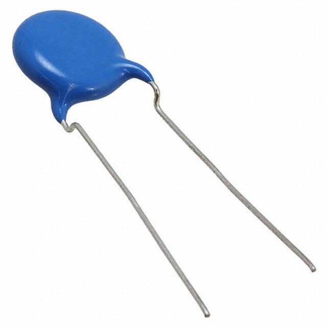
| 描述 | 热敏电阻 - PTC 603A 85A 62 PTC Thermistor |
| 产品分类 | 热敏电阻 - PTC |
| 产品手册 | |
| 产品图片 |
|
| rohs | 符合RoHS |
| 产品系列 | EPCOS B59603A0085A062 |
| 产品型号 | B59603A0085A062 |
| 产品种类 | 热敏电阻 - PTC |
| 商标 | EPCOS |
| 容差 | 15 % |
| 封装 | Reel |
| 封装/箱体 | 0603 |
| 尺寸 | 0.8 mm W x 1.6 mm L |
| 工作温度范围 | - 40 C to + 125 C |
| 工厂包装数量 | 4000 |
| 电阻 | 470 Ohms |
| 端接类型 | SMD/SMT |
| 零件号别名 | B59603A85A62 |


- 商务部:美国ITC正式对集成电路等产品启动337调查
- 曝三星4nm工艺存在良率问题 高通将骁龙8 Gen1或转产台积电
- 太阳诱电将投资9.5亿元在常州建新厂生产MLCC 预计2023年完工
- 英特尔发布欧洲新工厂建设计划 深化IDM 2.0 战略
- 台积电先进制程称霸业界 有大客户加持明年业绩稳了
- 达到5530亿美元!SIA预计今年全球半导体销售额将创下新高
- 英特尔拟将自动驾驶子公司Mobileye上市 估值或超500亿美元
- 三星加码芯片和SET,合并消费电子和移动部门,撤换高东真等 CEO
- 三星电子宣布重大人事变动 还合并消费电子和移动部门
- 海关总署:前11个月进口集成电路产品价值2.52万亿元 增长14.8%


PDF Datasheet 数据手册内容提取
PTC thermistors as limit temperature sensors SMD, EIA case sizes 0402, 0603, 0805, standard series Series/Type: B59404, B59601, B59602, B59603, B59701 Date: April 2020 ©TDKElectronicsAG2020.Reproduction,publicationanddisseminationofthispublication,enclosureshereto andtheinformationcontainedthereinwithoutTDKElectronics'priorexpressconsentisprohibited.
Sensors Limit temperature sensors, EIA case sizes 0402, 0603, 0805 Standard series Applications DC/DC converters Home appliances Dimmers Electronic ballasts Over-temperature protection of power components Secondary protection of battery packs SMPS Notebooks Features Fast and reliable response Suitable for reflow soldering only Compliant to RoHS directive 2002/95/EC UL approval to UL1434 for B59404A* and B59601A* (file number E69802) Lead-free terminations (tinned), except case size 0402 Options Other T or resistance values on request sense Delivery mode Blister tape (EIA case size 0805) or cardboard tape (EIA case sizes 0402 and 0603), 180-mm reel with 8-mm tape, taping to IEC 60286-3 Packing unit: 4.000 pcs. for EIA case sizes 0603 and 0805, 10.000 pcs. for EIA case size 0402 General technical data Max. operating voltage V 32 V DC max Minimum operating temperature (V ≤ Vmax) Top,min (cid:4)40 °C Maximum operating temperature (V ≤ V ) T 125 °C or T +25 °C °C max op,max sense,1 whichever is higher1) 1) T =140°CforB59404A0130A062 op,max PleasereadCautionsandwarningsand Page2of19 Importantnotesattheendofthisdocument.
Sensors Limit temperature sensors, EIA case sizes 0402, 0603, 0805 Standard series Electrical specifications and ordering codes EIA case sizes 0402 and 0603 R ΔR T T R Ordering code R R sense,1 sense,1 (V ≤ V ) (@ 4.7 kΩ) (@ 4.7 MΩ) (T +10 °C) max sense,1 Ω % °C °C kΩ EIA case size 0402, high ohmic types 10000 ±50 - 130 ±5 - B59404A0130A062 EIA case size 0603, standard types 470 ±50 75 ±5 - - B59601A0075A062 470 ±50 85 ±5 - - B59601A0085A062 470 ±50 95 ±5 - - B59601A0095A062 470 ±50 105 ±5 - - B59601A0105A062 470 ±50 115 ±5 - - B59601A0115A062 470 ±50 125 ±5 - - B59601A0125A062 470 ±50 135 ±5 - - B59601A0135A062 EIA case size 0603, tight temperature tolerance types 470 ±50 85 ±3 - ≥ 15 B59601A0085B062 470 ±50 95 ±3 - ≥ 40 B59601A0095B062 470 ±50 105 ±3 - ≥ 40 B59601A0105B062 470 ±50 115 ±3 - ≥ 40 B59601A0115B062 470 ±50 125 ±3 - ≥ 40 B59601A0125B062 Note: In order to limit self heating effects the electrical power during measurement should be below 2 mW for EIA case size 0402 and below 4 mW for EIA case size 0603. PleasereadCautionsandwarningsand Page3of19 Importantnotesattheendofthisdocument.
Sensors Limit temperature sensors, EIA case sizes 0402, 0603, 0805 Standard series Electrical specifications and ordering codes EIA case sizes 0603 and 0805 R ΔR T T T R R R Ordering code R R sense (V ≤ V ) (@ (typ.) (T (T (T max sense,1 sense,1 sense,1 2 (cid:5) RR) (@ Rmin) (cid:4)5°C) +5°C) +15°C) Ω % °C °C °C kΩ kΩ kΩ EIA case size 0603, tight resistance tolerance types 110 ±15 70 57 ±3 15 ≤ 1.1 ≥ 1.1 - B59602A0055B062 470 ±15 55 45 ±5 5 ≤ 4.7 ≥ 4.7 - B59603A0055A062 470 ±15 85 75 ±5 40 ≤ 4.7 ≥ 4.7 - B59603A0085A062 470 ±15 105 95 ±5 55 ≤ 4.7 ≥ 4.7 - B59603A0105A062 EIA case size 0805, standard types 680 ±50 70 - - ≤ 5.7 ≥ 5.7 ≥ 401) B59701A0070A062 680 ±50 90 - - ≤ 5.5 ≥ 13.3 ≥ 40 B59701A0090A062 680 ±50 100 - - ≤ 5.5 ≥ 13.3 ≥ 40 B59701A0100A062 680 ±50 110 - - ≤ 5.5 ≥ 13.3 ≥ 40 B59701A0110A062 680 ±50 120 - - ≤ 5.5 ≥ 13.3 ≥ 40 B59701A0120A062 680 ±50 130 - - ≤ 5.5 ≥ 13.3 ≥ 40 B59701A0130A062 680 ±50 140 - - ≤ 5.5 ≥ 13.3 ≥ 40 B59701A0140A062 Note: In order to limit self heating effects the electrical power during measurement should be below 4 mW for EIA case size 0603 and below 6 mW for EIA case size 0805. 1) R(T +25°C) sense,1 PleasereadCautionsandwarningsand Page4of19 Importantnotesattheendofthisdocument.
Sensors Limit temperature sensors, EIA case sizes 0402, 0603, 0805 Standard series Dimensional drawings in mm EIA case size 0402 Solder pad Recommended maximum dimensions (mm) EIA case size 0603 Solder pad Recommended maximum dimensions (mm) EIA case size 0805 Solder pad Recommended maximum dimensions (mm) PleasereadCautionsandwarningsand Page5of19 Importantnotesattheendofthisdocument.
Sensors Limit temperature sensors, EIA case sizes 0402, 0603, 0805 Standard series Characteristics (typical) for B59404A*, EIA case size 0402 PTC resistance R versus PTC temperature T (measured at low signal voltage). PTC PTC R and R values are typical values for reference only. min max PleasereadCautionsandwarningsand Page6of19 Importantnotesattheendofthisdocument.
Sensors Limit temperature sensors, EIA case sizes 0402, 0603, 0805 Standard series Characteristics (typical) for B59601A*, EIA case size 0603 PTC resistance R versus PTC temperature T PTC PTC (measured at low signal voltage) PleasereadCautionsandwarningsand Page7of19 Importantnotesattheendofthisdocument.
Sensors Limit temperature sensors, EIA case sizes 0402, 0603, 0805 Standard series Characteristics (typical) for B59601A*, EIA case size 0603 PTC resistance R versus PTC temperature T PTC PTC (measured at low signal voltage) PleasereadCautionsandwarningsand Page8of19 Importantnotesattheendofthisdocument.
Sensors Limit temperature sensors, EIA case sizes 0402, 0603, 0805 Standard series Characteristics (typical) for B59602A* and B59603A*, EIA case size 0603 PTC resistance R versus PTC temperature T PTC PTC (measured at low signal voltage) PleasereadCautionsandwarningsand Page9of19 Importantnotesattheendofthisdocument.
Sensors Limit temperature sensors, EIA case sizes 0402, 0603, 0805 Standard series Characteristics (typical) for B59603A*, EIA case size 0603 PTC resistance R versus PTC temperature T PTC PTC (measured at low signal voltage) PleasereadCautionsandwarningsand Page10of19 Importantnotesattheendofthisdocument.
Sensors Limit temperature sensors, EIA case sizes 0402, 0603, 0805 Standard series Characteristics (typical) for B59701A*, EIA case size 0805 PTC resistance R versus PTC temperature T PTC PTC (measured at low signal voltage) PleasereadCautionsandwarningsand Page11of19 Importantnotesattheendofthisdocument.
Sensors Limit temperature sensors, EIA case sizes 0402, 0603, 0805 Standard series Characteristics (typical) for B59701A*, EIA case size 0805 PTC resistance R versus PTC temperature T PTC PTC (measured at low signal voltage) PleasereadCautionsandwarningsand Page12of19 Importantnotesattheendofthisdocument.
Sensors Limit temperature sensors, EIA case sizes 0402, 0603, 0805 Standard series Reliability data Test Standard Test conditions (cid:6)ΔR25/R25(cid:6) Electrical endurance, IEC 60738-1 Room temperature: I , V ; < 20% smax max cycling Number of cycles: 100 Electrical endurance, IEC 60738-1 Storage at V and T (@ V ) < 25% max op,max max constant Test duration : 1000 h Damp heat IEC 60738-1 Temperature of air: 40 °C < 20% Relative humidity of air: 93% Duration: 56 days Test according to IEC 60068-2-78 Rapid change IEC 60738-1 T = T , T = T < 20% LCT op,min UCT op,max of temperature Number of cycles: 5 Test duration: 30 min Test according to IEC 60068-2-14, test Na Vibration IEC 60738-1 Frequency: 10 - 55 - 10 Hz < 20% Displacement amplitude: 0.75 mm Test duration: 3 × 2 h Test according to IEC 60028-2-6, test Fc Shock IEC 60738-1 Pulse shape: half-sine < 20% Acceleration: 400 m/s2 Pulse duration: 6 ms; 6 x 5000 pulses Test according to IEC 60068-2-27, test Ea Climatic sequence IEC 60738-1 Dry heat: T = 125 °C < 20% UCT Test duration: 16 h Damp heat first cycle Cold: TLCT= (cid:4)40 °C Test duration: 2 h Damp heat 5 cycles Tests performed according to IEC 60068-2-30 Bending test IEC 60738-1 Components reflow-soldered to test board < 20% Maximum bendig: 2 mm Test according to IEC 60068-2-21, test Ue Shear test Shearing of the component soldered on PCB No by a force of 5 N normal to components visible longitudinal axis damage Resistance to IEC 60738-1 Reflow soldering < 20% soldering heat T= 260 (cid:4)0/+5 °C, tPeak= 30 ... 40 s Pb-free soldering 3 times Test according to IEC 60068-2-58 PleasereadCautionsandwarningsand Page13of19 Importantnotesattheendofthisdocument.
Sensors Limit temperature sensors, EIA case sizes 0402, 0603, 0805 Standard series Cautions and warnings General TDK Electronics thermistors are designed for specific applications and should not be used for purposes not identified in our specifications, application notes and data books unless otherwise agreed with TDK Electronics during the design-in-phase. Ensure suitability of thermistor through reliability testing during the design-in phase. The ther- mistors should be evaluated taking into consideration worst-case conditions. Storage Store thermistors only in original packaging. Do not open the package prior to processing. Storage conditions in original packaging: storage temperature (cid:4)25 °C ... +45 °C, relative hu- midity ≤75% annual mean, maximum 95%, dew precipitation is inadmissible. Avoid contamination of thermistors surface during storage, handling and processing. Avoid storage of thermistor in harmful environment with effect on function on long-term opera- tion (examples given under operation precautions). Use thermistor within the following period after delivery: (cid:4) Through-hole devices (housed and leaded PTCs): 24 months (cid:4) Motor protection sensors, glass-encapsulated sensors and probe assemblies: 24 months (cid:4) Telecom pair and quattro protectors (TPP, TQP): 24 months (cid:4) Leadless PTC thermistors for pressure contacting: 12 months (cid:4) Leadless PTC thermistors for soldering: 6 months (cid:4) SMDs in EIA sizes 3225 and 4032, and for PTCs with metal tags: 24 months (cid:4) SMDs in EIA sizes 1210 and smaller: 12 months Handling PTCs must not be dropped. Chip-offs must not be caused during handling of PTCs. The ceramic and metallization of the components must not be touched with bare hands. Gloves are recommended. Avoid contamination of thermistor surface during handling. Soldering (where applicable) Use rosin-type flux or non-activated flux. Insufficient preheating may cause ceramic cracks. Rapid cooling by dipping in solvent is not recommended. Complete removal of flux is recommended. Standard PTC heaters are not suitable for soldering. PleasereadCautionsandwarningsand Page14of19 Importantnotesattheendofthisdocument.
Sensors Limit temperature sensors, EIA case sizes 0402, 0603, 0805 Standard series Mounting Electrode must not be scratched before/during/after the mounting process. Contacts and housing used for assembly with thermistor have to be clean before mounting. Es- pecially grease or oil must be removed. When PTC thermistors are encapsulated with sealing material, the precautions given in chapter "Mounting instructions", "Sealing and potting" must be observed. When the thermistor is mounted, there must not be any foreign body between the electrode of the thermistor and the clamping contact. The minimum force and pressure of the clamping contacts pressing against the PTC must be 10 N and 50 kPa, respectively. In case the assembly is exposed to mechanical shock and/ or vibration this force should be higher in order to avoid movement of the PTC during operation. During operation, the thermistor’s surface temperature can be very high. Ensure that adjacent components are placed at a sufficient distance from the thermistor to allow for proper cooling at the thermistors. Ensure that adjacent materials are designed for operation at temperatures comparable to the surface temperature of thermistor. Be sure that surrounding parts and materials can withstand this temperature. Avoid contamination of thermistor surface during processing. Operation Use thermistors only within the specified temperature operating range. Use thermistors only within the specified voltage and current ranges. Environmental conditions must not harm the thermistors. Use thermistors only in normal at- mospheric conditions. Avoid use in deoxidizing gases (chlorine gas, hydrogen sulfide gas, am- monia gas, sulfuric acid gas etc), corrosive agents, humid or salty conditions. Contact with any liquids and solvents should be prevented. Be sure to provide an appropriate fail-safe function to prevent secondary product damage caused by abnormal function (e.g. use VDR for limitation of overvoltage condition). This listing does not claim to be complete, but merely reflects the experience of TDK Electronics. Display of ordering codes for TDK Electronics products The ordering code for one and the same product can be represented differently in data sheets, data books, other publications, on the company website, or in order-related documents such as shipping notes, order confirmations and product labels. The varying representations of the ordering codes are due to different processes employed and do not affect the specifications of the respective products. Detailed information can be found on the Internet under www.tdk-electronics.tdk.com/orderingcodes. PleasereadCautionsandwarningsand Page15of19 Importantnotesattheendofthisdocument.
Sensors Limit temperature sensors, EIA case sizes 0402, 0603, 0805 Standard series Symbols and terms Symbol Term A Area C Capacitance C Heat capacity th f Frequency I Current I Maximum current max I Rated current R I Residual current res I PTC current PTC I Residual currrent r I Residual currrent in oil (for level sensors) r,oil I Residual currrent in air (for level sensors) r,air I Root-mean-square value of current RMS I Switching current S I Maximum switching current Smax LCT Lower category temperature N Number (integer) N Operating cycles at V , charging of capacitor c max N Switching cycles at V , failure mode f max P Power P Maximum power at 25 °C 25 P Electrical power el P Dissipation power diss R Generator internal resistance G R Minimum resistance min R Rated resistance @ rated temperature T R R ΔR Tolerance of R R R R Parallel resistance P R PTC resistance PTC R Reference resistance ref R Series resistance S R Resistance at 25 °C 25 R Resistance matching per reel/ packing unit at 25 °C 25,match ΔR Tolerance of R 25 25 PleasereadCautionsandwarningsand Page16of19 Importantnotesattheendofthisdocument.
Sensors Limit temperature sensors, EIA case sizes 0402, 0603, 0805 Standard series T Temperature t Time T Ambient temperature A t Thermal threshold time a T Ferroelectric Curie temperature C t Settling time (for level sensors) E T Rated temperature @ 25 °C or otherwise specified in the data sheet R T Sensing temperature sense T Operating temperature op T PTC temperature PTC t Response time R T Reference temperature ref T Temperature at minimum resistance Rmin t Switching time S T Surface temperature surf UCT Upper category temperature V or V Voltage (with subscript only for distinction from volume) el V Maximum DC charge voltage of the surge generator c(max) V Maximum voltage applied at fault conditions in protection mode F,max V Root-mean-square value of voltage RMS V Breakdown voltage BD V Insulation test voltage ins V Maximum link voltage link,max V Maximum operating voltage max V Maximum dynamic (short-time) operating voltage max,dyn V Measuring voltage meas V Maximum measuring voltage meas,max V Rated voltage R V Voltage drop across a PTC thermistor PTC α Temperature coefficient Δ Tolerance, change δ Dissipation factor th τ Thermal cooling time constant th λ Failure rate Lead spacing (in mm) PleasereadCautionsandwarningsand Page17of19 Importantnotesattheendofthisdocument.
Important notes The following applies to all products named in this publication: 1. Some parts of this publication contain statements about the suitability of our products for certain areas of application. These statements are based on our knowledge of typical re- quirements that are often placed on our products in the areas of application concerned. We nevertheless expressly point out that such statements cannot be regarded as binding statements about the suitability of our products for a particular customer application. As a rule, we are either unfamiliar with individual customer applications or less familiar with them than the customers themselves. For these reasons, it is always ultimately incumbent on the customer to check and decide whether a product with the properties described in the product specification is suitable for use in a particular customer application. 2. We also point out that in individual cases, a malfunction of electronic components or failure before the end of their usual service life cannot be completely ruled out in the current state of the art, even if they are operated as specified. In customer applications requiring a very high level of operational safety and especially in customer applications in which the malfunction or failure of an electronic component could endanger human life or health (e.g. in accident prevention or lifesaving systems), it must therefore be ensured by means of suitable design of the customer application or other action taken by the customer (e.g. installation of protective circuitry or redundancy) that no injury or damage is sustained by third parties in the event of malfunction or failure of an electronic component. 3. The warnings, cautions and product-specific notes must be observed. 4. In order to satisfy certain technical requirements, some of the products described in this publication may contain substances subject to restrictions in certain jurisdictions (e.g. because they are classed as hazardous). Useful information on this will be found in our Ma- terial Data Sheets on the Internet (www.tdk-electronics.tdk.com/material). Should you have any more detailed questions, please contact our sales offices. 5. We constantly strive to improve our products. Consequently, the products described in this publication may change from time to time. The same is true of the corresponding product specifications. Please check therefore to what extent product descriptions and specifications contained in this publication are still applicable before or when you place an order. We also reserve the right to discontinue production and delivery of products. Consequently, we cannot guarantee that all products named in this publication will always be available. The aforementioned does not apply in the case of individual agreements deviating from the fore- going for customer-specific products. 6. Unless otherwise agreed in individual contracts, all orders are subject to our General Terms and Conditions of Supply. Page18of19
Important notes 7. Our manufacturing sites serving the automotive business apply the IATF 16949 standard. The IATF certifications confirm our compliance with requirements regarding the quality management system in the automotive industry. Referring to customer requirements and customer specific requirements (“CSR”) TDK always has and will continue to have the policy of respecting individual agreements. Even if IATF 16949 may appear to support the acceptance of unilateral requirements, we hereby like to emphasize that only requirements mutually agreed upon can and will be implemented in our Quality Management System. For clarification purposes we like to point out that obligations from IATF 16949 shall only become legally binding if individually agreed upon. 8. The trade names EPCOS, CeraCharge, CeraDiode, CeraLink, CeraPad, CeraPlas, CSMP, CTVS, DeltaCap, DigiSiMic, ExoCore, FilterCap, FormFit, LeaXield, MiniBlue, MiniCell, MKD, MKK, MotorCap, PCC, PhaseCap, PhaseCube, PhaseMod, PhiCap, PowerHap, PQSine, PQvar, SIFERRIT, SIFI, SIKOREL, SilverCap, SIMDAD, SiMic, SIMID, SineFormer, SIOV, ThermoFuse, WindCap are trademarks registered or pending in Europe and in other countries. Further information will be found on the Internet at www.tdk-electronics.tdk.com/trademarks. Release 2018-10 Page19of19