ICGOO在线商城 > 传感器,变送器 > 温度传感器 - NTC 热敏电阻器 > B57621C5102J062

 Datasheet下载
- 型号: B57621C5102J062
- 制造商: EPCOS
- 库位|库存: xxxx|xxxx
- 要求:
| 数量阶梯 | 香港交货 | 国内含税 |
| +xxxx | $xxxx | ¥xxxx |
查看当月历史价格
查看今年历史价格
B57621C5102J062产品简介:
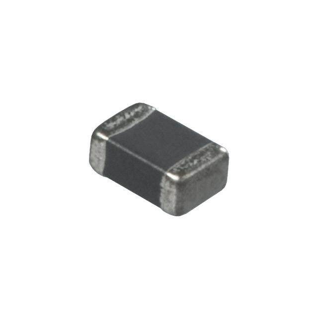
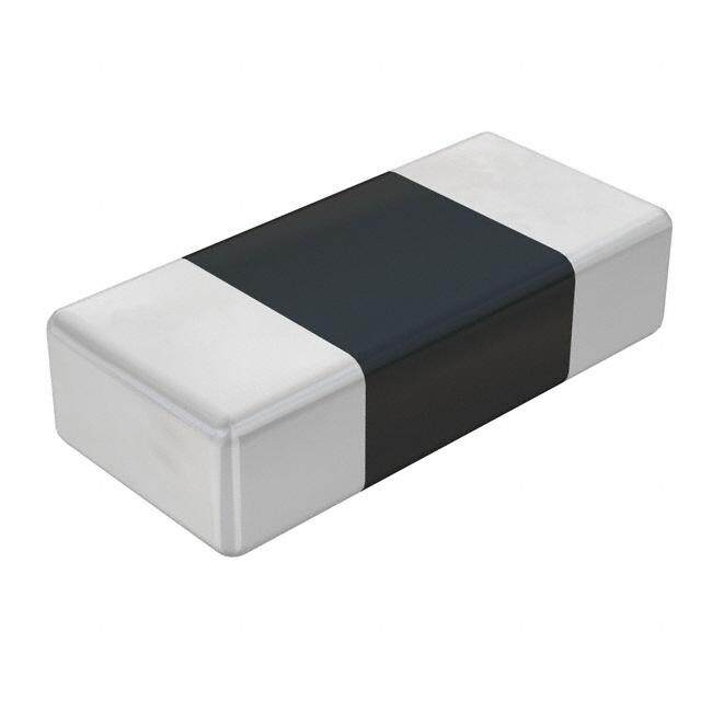
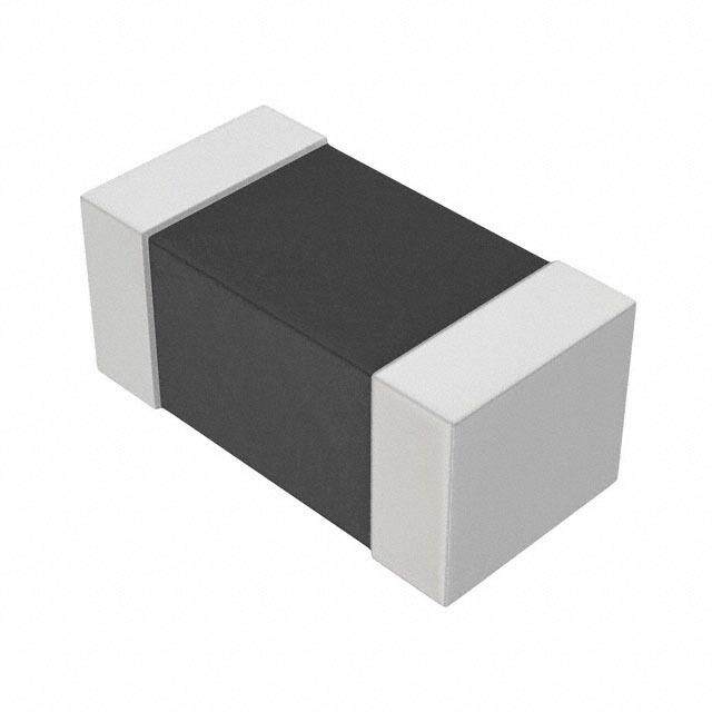
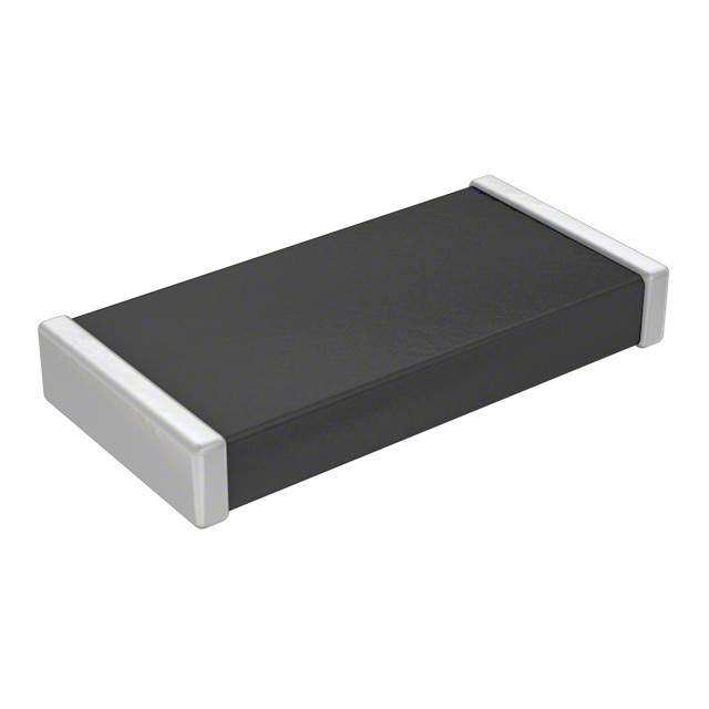
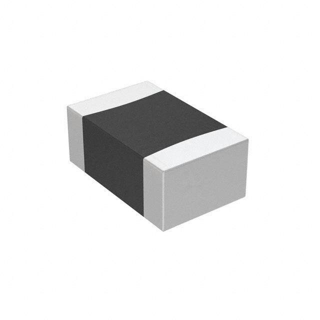
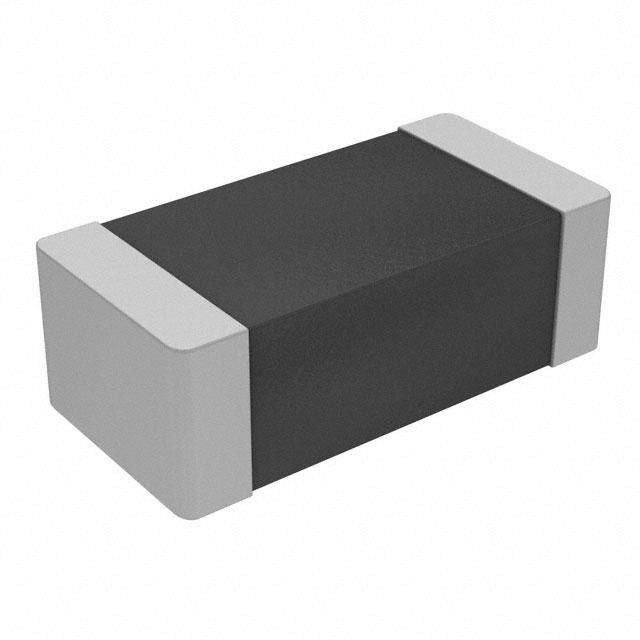
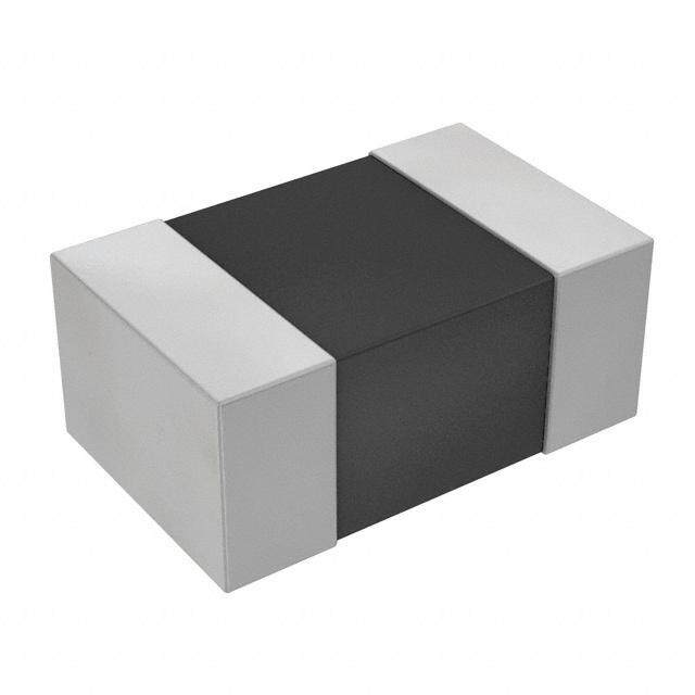
ICGOO电子元器件商城为您提供B57621C5102J062由EPCOS设计生产,在icgoo商城现货销售,并且可以通过原厂、代理商等渠道进行代购。 B57621C5102J062价格参考¥1.53-¥5.21。EPCOSB57621C5102J062封装/规格:温度传感器 - NTC 热敏电阻器, NTC Thermistor 1k 1206 (3216 Metric)。您可以下载B57621C5102J062参考资料、Datasheet数据手册功能说明书,资料中有B57621C5102J062 详细功能的应用电路图电压和使用方法及教程。
| 参数 | 数值 |
| 品牌 | EPCOS |
| 产品目录 | 无源元件 |
| 描述 | 热敏电阻 - NTC 1K J62 B-3450 NTC Thermistor 1206 |
| 产品分类 | 热敏电阻 - NTC |
| 产品手册 | |
| 产品图片 |
|
| rohs | 符合RoHS |
| 产品系列 | EPCOS B57621C5102J062 |
| 产品型号 | B57621C5102J062 |
| 产品种类 | 热敏电阻 - NTC |
| 功率额定值 | 300 mW |
| 商标 | EPCOS |
| 容差 | 5 % |
| 封装 | Reel |
| 封装/箱体 | 1206 |
| 尺寸 | 1.6 mm W x 3.2 mm L x 1.3 mm H |
| 工作温度范围 | - 55 C to + 125 C |
| 工厂包装数量 | 2000 |
| 电阻 | 1 kOhms |
| 端接类型 | SMD/SMT |
| 类型 | NTC |
| 系列 | B57621C5 |


- 商务部:美国ITC正式对集成电路等产品启动337调查
- 曝三星4nm工艺存在良率问题 高通将骁龙8 Gen1或转产台积电
- 太阳诱电将投资9.5亿元在常州建新厂生产MLCC 预计2023年完工
- 英特尔发布欧洲新工厂建设计划 深化IDM 2.0 战略
- 台积电先进制程称霸业界 有大客户加持明年业绩稳了
- 达到5530亿美元!SIA预计今年全球半导体销售额将创下新高
- 英特尔拟将自动驾驶子公司Mobileye上市 估值或超500亿美元
- 三星加码芯片和SET,合并消费电子和移动部门,撤换高东真等 CEO
- 三星电子宣布重大人事变动 还合并消费电子和移动部门
- 海关总署:前11个月进口集成电路产品价值2.52万亿元 增长14.8%
PDF Datasheet 数据手册内容提取
NTC thermistors for temperature measurement SMD NTC thermistors, EIA case size 1206 (3216), standard series Series/Type: B57621C5 Date: February2019 ©TDKElectronicsAG2019.Reproduction,publicationanddisseminationofthispublication,enclosureshereto andtheinformationcontainedthereinwithoutTDKElectronics'priorexpressconsentisprohibited.
Temperaturemeasurementandcompensation B57621C5 SMDNTCthermistors,casesize1206(3216) Standardseries Applications Dimensionaldrawing Temperaturemeasurementand compensation Features MultilayerSMDNTCwith/withoutinner electrodes Nickelbarriertermination Fortemperaturemeasurementupto125(cid:176) C Excellentlong-termagingstabilityinhigh temperatureenvironment Highmechanicalrobustness Shortresponsetime 100%Pbfree Options Dimensionsinmm Alternativeresistanceratings,resistance Approx.weight24mg tolerancesandBvaluetolerancesavailable onrequest. Deliverymode Blistertape,180-mmreel(standard) Generaltechnicaldata Operatingtemperaturerange Top (cid:4)55...125 (cid:176) C Max.power (at25(cid:176) C,onPCB) P 1) 300 mW 25 Resistancetolerance D R /R – 5,– 10 % R R Ratedtemperature T 25 (cid:176) C R Dissipationfactor (onPCB) d 1) approx.5 mW/K th Thermalcoolingtimeconstant (onPCB) t 1) approx.10 s c Heatcapacity C 1) approx.50 mJ/K th Electricalspecificationandorderingcodes R25 D RR/RR No.ofR/T B25/50 B25/85 B25/100 Orderingcode W % characteristic K K K 1.0k – 5,– 10 3206 3420 3440 3450– 3% B57621C5102+062 4.7k – 5,– 10 1309 3430 3500 3520– 3% B57621C5472+062 10k – 5,– 10 1010 3470 3510 3530– 3% B57621C5103+062 += Resistancetolerance J= – 5% K=– 10% 1) Dependsonmountingsituation PleasereadCautionsandwarningsand Page2of25 Importantnotesattheendofthisdocument.
Temperaturemeasurementandcompensation B57621C5 SMDNTCthermistors,casesize1206(3216) Standardseries Reliabilitydata SMDNTCthermistorsaretestedinaccordancewithIEC60068.Thepartsaremountedona standardizedPCBinaccordancewithIEC60539-1. Test Standard Testconditions D R /R Remarks 25 25 (typical) Storagein IEC Storageatupper <3%1) dryheat 60068-2-2 categorytemperature JISC0021 T:(125– 2)(cid:176) C t:1000h Storageindamp IEC Temperatureofair:(40– 2)(cid:176) C <3% Novisible heat,steadystate 60068-2-78 Relativehumidityofair: damage JISC0022 (93+2/(cid:4)3)% Duration:21days Rapidtemperature IEC Lowertesttemperature:(cid:4)55(cid:176) C <3% cycling 60068-2-14 Uppertesttemperature:125(cid:176) C JISC0025 Numberofcycles:10 Endurance P :300mW <5% max T:(65– 2)(cid:176) C t:1000h Solderability IEC Solderability: 95%of 60068-2-58 (215– 3)(cid:176) C,(3– 0.3)s terminations JISC0054 (245– 5)(cid:176) C,(3– 0.3)s wetted Resistancetosolderingheat: (260– 5)(cid:176) C,(10– 1)s Resistancedrift Reflowsolderingprofile <5% aftersoldering Wavesolderingprofile 1) ExcepttypeB57621C5102+062andB57621C5472+062D R25/R25:<6% PleasereadCautionsandwarningsand Page3of25 Importantnotesattheendofthisdocument.
Temperaturemeasurementandcompensation B57621C5 SMDNTCthermistors,casesize1206(3216) Standardseries R/Tcharacteristics R/TNo. 1010 1309 3206 T((cid:176) C) B =3530K B =3520K B =3450K 25/100 25/100 25/100 R/R a (%/K) R/R a (%/K) R/R a (%/K) T 25 T 25 T 25 (cid:4)55.0 52.826 6.4 48.46 6.1 59.147 6.7 (cid:4)50.0 38.643 6.1 35.8 6.0 42.651 6.4 (cid:4)45.0 28.574 5.9 26.694 5.8 31.088 6.2 (cid:4)40.0 21.346 5.7 20.085 5.6 22.903 6.0 (cid:4)35.0 16.1 5.5 15.247 5.4 17.052 5.8 (cid:4)30.0 12.256 5.4 11.674 5.3 12.827 5.6 (cid:4)25.0 9.4071 5.2 9.0124 5.1 9.7461 5.4 (cid:4)20.0 7.2862 5.0 7.0136 4.9 7.477 5.2 (cid:4)15.0 5.6835 4.9 5.5001 4.8 5.7897 5.0 (cid:4)10.0 4.4698 4.7 4.3451 4.6 4.5234 4.9 (cid:4)5.0 3.5385 4.6 3.4569 4.5 3.5643 4.7 0.0 2.8222 4.5 2.7688 4.4 2.8316 4.5 5.0 2.2649 4.3 2.2321 4.2 2.2671 4.4 10.0 1.83 4.2 1.8105 4.1 1.8287 4.2 15.0 1.4872 4.1 1.4773 4.0 1.4855 4.1 20.0 1.2161 4.0 1.2122 3.9 1.2149 4.0 25.0 1.0000 3.9 1.0000 3.8 1.0000 3.8 30.0 0.82677 3.8 0.82924 3.7 0.82816 3.7 35.0 0.68708 3.6 0.69105 3.6 0.68985 3.6 40.0 0.57401 3.5 0.57861 3.5 0.57784 3.5 45.0 0.48181 3.5 0.48666 3.4 0.48658 3.4 50.0 0.40638 3.4 0.4111 3.3 0.41181 3.3 55.0 0.34427 3.3 0.34872 3.3 0.3502 3.2 60.0 0.29296 3.2 0.29699 3.2 0.29918 3.1 65.0 0.25035 3.1 0.2539 3.1 0.25672 3.0 70.0 0.21478 3.0 0.21786 3.0 0.2212 2.9 75.0 0.18501 2.9 0.18759 3.0 0.19136 2.9 80.0 0.15995 2.9 0.16208 2.9 0.16618 2.8 85.0 0.13881 2.8 0.1405 2.8 0.14484 2.7 90.0 0.12088 2.7 0.12217 2.8 0.12668 2.7 95.0 0.10563 2.7 0.10656 2.7 0.11117 2.6 100.0 0.092597 2.6 0.093213 2.6 0.09787 2.5 105.0 0.081442 2.5 0.081767 2.6 0.086428 2.5 110.0 0.071842 2.5 0.071922 2.5 0.076549 2.4 115.0 0.063571 2.4 0.063428 2.5 0.067992 2.3 120.0 0.056407 2.4 0.056078 2.4 0.060555 2.3 125.0 0.050196 2.3 0.049702 2.4 0.054073 2.2 PleasereadCautionsandwarningsand Page4of25 Importantnotesattheendofthisdocument.
Temperaturemeasurementandcompensation B57621C5 SMDNTCthermistors,casesize1206(3216) Standardseries Tapingandpacking 1 TapingofSMDNTCthermistors TapeandreelpackingaccordingtoIEC60286-3. Tapematerial:Cardboardorblister,tapewidth8– 0.30mm 2 Reelpacking Dimensionsinmm 8-mmtape 180-mmreel 330-mmreel A 180+0/(cid:4)3 330+0/(cid:4)2.0 W1 8.4+1.5/(cid:4)0 8.4+1.5/(cid:4)0 W 14.4max. 14.4max. 2 Leader,trailer PleasereadCautionsandwarningsand Page5of25 Importantnotesattheendofthisdocument.
Temperaturemeasurementandcompensation B57621C5 SMDNTCthermistors,casesize1206(3216) Standardseries Packingunitsfordiscretechip Casesize Chipthickness Cardboardtape Blistertape ˘ 180-mmreel ˘ 330-mmreel inch/mm th W W pcs. pcs. 0402/1005 0.5mm 8mm (cid:4) 10000 50000 0603/1608 0.8mm 8mm 8mm 4000 16000 0805/2012 0.8mm (cid:4) 8mm 2000/4000 16000 1.2mm (cid:4) 8mm 3000 12000 1206/3216 0.8mm (cid:4) 8mm 2000 12000 1.2mm (cid:4) 8mm 4000 12000 3 Packingcodes Thelasttwodigitsofthecompleteorderingcodestatethepackingmode: Lasttwodigits 60 SMD Cardboardtape 180-mmreelpacking 62 SMD Blistertape 180-mmreelpacking 70 SMD Cardboardtape 330-mmreelpacking 72 SMD Blistertape 330-mmreelpacking PleasereadCautionsandwarningsand Page6of25 Importantnotesattheendofthisdocument.
Temperaturemeasurementandcompensation B57621C5 SMDNTCthermistors,casesize1206(3216) Standardseries 4 TapingofradialleadedNTCthermistors Dimensionsandtolerances LeadspacingF=2.5mmand5.0mm(tapingtoIEC60286-2) Dimensions(mm) Lead Lead Toleranceof Remarks spacing spacing leadspacing 2.5mm 5mm 2.5/5mm w 11.0 11.5 max. th 5.0 6.0 max. d 0.5/0.6 0.5/0.6 – 0.05 P 12.7 12.7 – 0.3 – 1mm/20sprocketholes 0 P 5.1 3.85 – 0.7 1 F 2.5 5.0 +0.6/(cid:4)0.1 D h 0 0 – 2.0 measuredattopofcomponentbody D p 0 0 – 1.3 W 18.0 18.0 – 0.5 W 5.5 5.5 min. peel-offforce‡ 5N 0 W1 9.0 9.0 +0.75/(cid:4)0.5 W 3.0 3.0 max. 2 H 18.0 18.0 +2.0/(cid:4)0 H 16.0 16.0 – 0.5 0 H 32.2 32.2 max. 1 D 4.0 4.0 – 0.2 0 t 0.9 0.9 max. withoutwires L 11.0 11.0 max. L 4.0 4.0 max. 1 PleasereadCautionsandwarningsand Page7of25 Importantnotesattheendofthisdocument.
Temperaturemeasurementandcompensation B57621C5 SMDNTCthermistors,casesize1206(3216) Standardseries Typesofpacking Ammopacking Ammo x y z type I 80 240 210 Packingunit:1000-2000pcs./reel Reelpacking Packingunit:1000-2000pcs./reel Reeldimensions(inmm) Reeltype d f n w I 360max. 31– 1 approx.45 54max. PleasereadCautionsandwarningsand Page8of25 Importantnotesattheendofthisdocument.
Temperaturemeasurementandcompensation B57621C5 SMDNTCthermistors,casesize1206(3216) Standardseries Cassettepacking Packingunit:1000-2000pcs./cassette Bulkpacking Thecomponentsarepackedincardboardboxes,thesizeofwhichdependsontheorderquantity. PleasereadCautionsandwarningsand Page9of25 Importantnotesattheendofthisdocument.
Temperaturemeasurementandcompensation B57621C5 SMDNTCthermistors,casesize1206(3216) Standardseries 5 Packingcodes Thelasttwodigitsofthecompleteorderingcodestatethepackingmode: Lasttwodigits 00,01,02,03,04, (cid:4) Bulk (cid:4) 05,06,07,08 40,41 (cid:4) Bulk (cid:4) 45 (cid:4) Bulk (cid:4) 50 Radialleads,kinked Cardboardtape Cassettepacking 51 Radialleads,kinked Cardboardtape 360-mmreelpacking 52 Radialleads,straight Cardboardtape Cassettepacking 53 Radialleads,straight Cardboardtape 360-mmreelpacking 54 Radialleads,kinked Cardboardtape AMMOpacking 55 Radialleads,straight Cardboardtape AMMOpacking (Ifnopackingcodeisindicated,thiscorrespondsto40) Example1: B57164K0102J000 Bulk B57164K0102J052 Cardboardtape,cassettepacking Example2: B57881S0103F002 Bulk B57881S0103F251 Cardboardtape,reelpacking PleasereadCautionsandwarningsand Page10of25 Importantnotesattheendofthisdocument.
Temperaturemeasurementandcompensation B57621C5 SMDNTCthermistors,casesize1206(3216) Standardseries Mountinginstructions 1 Soldering 1.1 LeadedNTCthermistors LeadedthermistorscomplywiththesolderabilityrequirementsspecifiedbyCECC. When soldering, care must be taken that the NTC thermistors are not damaged by excessive heat.Thefollowingmaximumtemperatures,maximumtimespansandminimumdistanceshave tobeobserved: Dipsoldering Ironsoldering Bathtemperature max.260(cid:176) C max.360(cid:176) C Solderingtime max.4s max.2s Distancefromthermistor min.6mm min.6mm Undermoreseveresolderingconditionstheresistancemaychange. 1.1.1 Wavesoldering Temperaturecharacteristicatcomponentterminalwithdualwavesoldering PleasereadCautionsandwarningsand Page11of25 Importantnotesattheendofthisdocument.
Temperaturemeasurementandcompensation B57621C5 SMDNTCthermistors,casesize1206(3216) Standardseries 1.2 LeadlessNTCthermistors In case of NTC thermistors without leads, soldering is restricted to devices which are provided with a solderable metallization. The temperature shock caused by the application of hot solder mayproducefinecracksintheceramic,resultinginchangesinresistance. To prevent leaching of the metallization, solder with silver additives or with a low tin content shouldbeused.Inaddition,solderingmethodsshouldbeemployedwhichpermitshortsoldering times. 1.3 SMDNTCthermistors SMDNTCthermistorscanbeprovidedwithanickelbarrierterminationoronspecialrequestwith silver-palladium termination. The use of no-clean solder products is recommended. In any case mild,non-activatedfluxesshouldbeused.Fluxresiduesaftersolderingshouldbeminimized. SMDNTCswithAgPdterminationarenotapprovedforlead-freesoldering. Nickelbarriertermination Figure1 SMDNTCthermistors,structureofnickel barriertermination Thenickelbarrierlayerofthesilver/nickel/tintermination(seefigure1)preventsleachingofthe silverbasemetallizationlayer.Thisallowsgreatflexibilityintheselectionofsolderingparameters. Thetinpreventsthenickellayerfromoxidizingandthusensuresbetterwettingbythesolder.The nickel barrier termination is tested for all commonly-used soldering methods according to IEC 60068-2-58. Insufficient preheating may cause ceramic cracks. Rapid cooling by dipping in solventisnotrecommended. Thefollowingtestandprocessconditionsapplyfornickelbarriertermination. PleasereadCautionsandwarningsand Page12of25 Importantnotesattheendofthisdocument.
Temperaturemeasurementandcompensation B57621C5 SMDNTCthermistors,casesize1206(3216) Standardseries 1.3.1 Solderability(testtoIEC60068-2-58) Preconditioning:ImmersionintofluxF-SW32. Evaluationcriterion:Wettingofsolderingareas‡ 95%. Solder Bathtemperature((cid:176) C) Dwelltime(s) SnPb60/40 215– 3 3– 0.3 SnAg(3.0...4.0),Cu(0.5...0.9) 245– 3 3– 0.3 1.3.2 Resistancetosolderingheat(testtoIEC60068-2-58) Preconditioning:ImmersionintofluxF-SW32. Evaluationcriterion:Leachingofsideedges£ 1/3. Solder Bathtemperature((cid:176) C) Dwelltime(s) SnPb60/40 260– 5 10– 1 SnAg(3.0...4.0),Cu(0.5...0.9) 260– 5 10– 1 1.3.3 Reflowsoldering Temperaturerangesforreflowsolderingacc.toIEC60068-2-58recommendations. PleasereadCautionsandwarningsand Page13of25 Importantnotesattheendofthisdocument.
Temperaturemeasurementandcompensation B57621C5 SMDNTCthermistors,casesize1206(3216) Standardseries Profilefeature Sn-Pbeutecticassembly Pb-freeassembly Preheatandsoak -Temperaturemin T 100(cid:176) C 150(cid:176) C smin -Temperaturemax T 150(cid:176) C 200(cid:176) C smax -Time t tot 60...120s 60...120s smin smax Averageramp-uprate T toT 3(cid:176) C/smax. 3(cid:176) C/smax. smax p Liquidoustemperature T 183(cid:176) C 217(cid:176) C L Timeatliquidous t 40...150s 40...150s L Peakpackagebodytemperature T 215(cid:176) C...260(cid:176) C1) 235(cid:176) C...260(cid:176) C p Timeabove(TP(cid:4)5(cid:176) C) tp 10...40s 10...40s Averageramp-downrate T toT 6(cid:176) C/smax. 6(cid:176) C/smax. p smax Time25(cid:176) Ctopeaktemperature max.8minutes max.8minutes 1) Dependingonpackagethickness. Notes: Alltemperaturesrefertotopsideofthepackage,measuredonthepackagebody surface. Numberofreflowcycles:3 Ironsolderingshouldbeavoided,hotairmethodsarerecommendedforrepair purposes. Solderjointprofilesforsilver/nickel/tinterminations PleasereadCautionsandwarningsand Page14of25 Importantnotesattheendofthisdocument.
Temperaturemeasurementandcompensation B57621C5 SMDNTCthermistors,casesize1206(3216) Standardseries 1.3.4 Recommendedgeometryofsolderpads Recommendedmaximumdimensions(mm) Casesize A B C inch/mm 0402/1005 0.6 0.6 1.7 0603/1608 1.0 1.0 3.0 0805/2012 1.3 1.2 3.4 1206/3216 1.8 1.2 4.5 2 Conductiveadhesion Analternativetosolderingforsilver-palladiumterminatedcomponentsisthegluingofthermistors with conductive adhesives. The benefit of this method is that it involves no thermal stress. The adhesivesusedmustbechemicallyinert. 3 Clampcontacting Pressurecontactingbymeansofclampsisparticularlysuitableforapplicationsinvolvingfrequent switchingandhighturn-onpowers. 4 Robustnessofterminations(leadedtypes) The leads meet the requirements of IEC 60068-2-21. They may not be bent closer than 4 mm from the solder joint on the thermistor body or from the point at which they leave the feed- throughs.Duringbending,anymechanicalstressattheoutletoftheleadsmustberemoved.The bendingradiusshouldbeatleast0.75mm. PleasereadCautionsandwarningsand Page15of25 Importantnotesattheendofthisdocument.
Temperaturemeasurementandcompensation B57621C5 SMDNTCthermistors,casesize1206(3216) Standardseries Tensilestrength: TestUa1: ValueofappliedforceforUa1test: Diameter(d)of Forcewithtoleranceof– 10% correspondingroundleads ˘£ 0.25mm 1.0N 0.25<˘£ 0.35mm 2.5N 0.35<˘£ 0.50mm 5.0N 0.50<˘£ 0.80mm 10.0N Bendingstrength: TestUb: Two90(cid:176) -bendsinoppositedirections ValueofappliedforceforUbtest: Diameter(d)of Forcewithtoleranceof– 10% correspondingroundleads ˘£ 0.25mm 0.5N 0.25<˘£ 0.35mm 1.25N 0.35<˘£ 0.50mm 2.5N 0.50<˘£ 0.80mm 5N Torsionalstrength: TestUc:severity2 Theleadisbentby90(cid:176) atadistanceof6to6.5mmfromthethermistorbody. Thebendingradiusoftheleadsshouldbeapprox.0.75mm.Twotorsionsof 180(cid:176) each(severity2). Whensubjectingleadstomechanicalstress,thefollowingshouldbeobserved: Tensilestressonleads Duringmountingandoperationtensileforcesontheleadsaretobeavoided. Bendingofleads Bendingoftheleadsdirectlyonthethermistorbodyisnotpermissible. A lead may be bent at a minimum distance of twice the wire's diameter +4 mm from the solder jointonthethermistorbody.Duringbendingthewiremustbemechanicallyrelievedatitsoutlet. Thebendingradiusshouldbeatleast0.75mm. PleasereadCautionsandwarningsand Page16of25 Importantnotesattheendofthisdocument.
Temperaturemeasurementandcompensation B57621C5 SMDNTCthermistors,casesize1206(3216) Standardseries 5 Sealingandpotting Sealingorpottingprocessescanaffectthereliabilityofthecomponent. Whenthermistorsaresealed,pottedorovermolded,theremustbenomechanicalstresscaused by thermal expansion during the production process (curing / overmolding process) and during lateroperation.Theuppercategorytemperatureofthethermistormustnotbeexceeded.Ensure thatthematerialsused(sealing/pottingcompoundand plasticmaterial)arechemicallyneutral. Asthermistorsaretemperaturesensitivecomponentsitshouldbeconsideredthatmoldingcanaf- fectthethermalsurroundingandmayinfluencee.g.theresponsetime. Extensivetestingisencouragedinordertodeterminewhetherovermoldingorpottinginfluences thefunctionalityand/orreliabilityofthecomponent. 6 Cleaning Cleaningprocessescanaffectthereliabilityofthecomponent. Ifcleaningisnecessary,mildcleaningagentsarerecommended.Cleaningagentsbasedonwa- ter are not allowed. Washing processes may damage the product due to the possible static or cyclicmechanicalloads(e.g.ultrasoniccleaning).Theymaycausecrackswhichmightleadtore- ducedreliabilityand/orlifetime. 7 Storage Inordertomaintaintheirsolderability,thermistorsmustbestoredinanon-corrosiveatmosphere. Humidity,temperatureandcontainermaterialsarecriticalfactors. DonotstoreSMDswheretheyareexposedtoheatordirectsunlight.Otherwise,thepackingma- terial may be deformed or SMDs may stick together, causing problems during mounting. After openingthefactoryseals,suchaspolyvinyl-sealedpackages,usetheSMDsassoonaspossible. Thecomponentsshouldbeleftintheoriginalpacking.Touchingthemetallizationofunsoldered thermistorsmaychangetheirsolderingproperties. Storagetemperature: (cid:4)25(cid:176) Cupto45(cid:176) C Relativehumidity(withoutcondensation): £ 75%annualmean <95%,maximum30daysperannum SolderthethermistorslistedinthisdatabookaftershipmentfromTDKwithinthetimespecified: SMDswithAgPdtermination: 6months SMDswithnickelbarriertermination: 12months Leadlesscomponents: 12months Leadedcomponents: 24months PleasereadCautionsandwarningsand Page17of25 Importantnotesattheendofthisdocument.
Temperaturemeasurementandcompensation B57621C5 SMDNTCthermistors,casesize1206(3216) Standardseries 8 PlacementandorientationofSMDNTCthermistorsonPCB a)Componentplacement ItisrecommendedthatthePCboard shouldbeheldbymeansofsome adequatesupportingpinssuchas shownlefttopreventtheSMDsfrom beingdamagedorcracked. b)Cracks Whenplacingacomponentnearan areawhichisapttobendoragrid grooveonthePCboard,itisadvisable tohavebothelectrodessubjectedto uniformstress,ortopositionthe component'selectrodesatrightangles tothegridgrooveorbendingline(see c)Componentorientation). c)Componentorientation Chooseamountingpositionthat minimizesthestressimposedonthe chipduringflexingorbendingofthe board. PleasereadCautionsandwarningsand Page18of25 Importantnotesattheendofthisdocument.
Temperaturemeasurementandcompensation B57621C5 SMDNTCthermistors,casesize1206(3216) Standardseries Cautionsandwarnings General See"Importantnotes"attheendofthisdocument. Storage Storethermistorsonlyinoriginalpackaging.Donotopenthepackagepriortoprocessing. Storageconditionsinoriginalpackaging:storagetemperature(cid:4)25(cid:176) C...+45(cid:176) C,relative humidity£ 75%annualmean,<95%maximum30daysperannum,dewprecipitationis inadmissible. Donotstorethermistorswheretheyareexposedtoheatordirectsunlight.Otherwise,the packingmaterialmaybedeformedorcomponentsmaysticktogether,causingproblemsduring mounting. Avoidcontaminationofthermistorsurfaceduringstorage,handlingandprocessing. Avoidstorageofthermistorsinharmfulenvironmentslikecorrosivegases(SO,Cletc). x Usethecomponentsassoonaspossibleafteropeningtheoriginalpackaging. SolderthermistorswithinthetimespecifiedaftershipmentfromTDK. Forleadedcomponentsthisis24months,forSMDcomponentswithnickelbarriertermination 12months,forleadlesscomponentsthisis12months,forSMDcomponentswithAgPd termination6months. Handling NTCthermistorsmustnotbedropped.Chip-offsoranyotherdamagemustnotbecaused duringhandlingofNTCs. Donottouchcomponentswithbarehands.Glovesarerecommended. Avoidcontaminationofthermistorsurfaceduringhandling. Washingprocessesmaydamagetheproductduetothepossiblestaticorcyclicmechanical loads(e.g.ultrasoniccleaning).Theymaycausecrackstodevelopontheproductanditsparts, whichmightleadtoreducedreliabilityorlifetime. Bending/twistingleads Alead(wire)maybebentataminimumdistanceoftwicethewire’sdiameterplus4mmfrom thecomponentheadorhousing.Whenbendingensurethewireismechanicallyrelievedatthe componentheadorhousing.Thebendingradiusshouldbeatleast0.75mm. Soldering Useresin-typefluxornon-activatedflux. Insufficientpreheatingmaycauseceramiccracks. Rapidcoolingbydippinginsolventisnotrecommended. Completeremovaloffluxisrecommended. PleasereadCautionsandwarningsand Page19of25 Importantnotesattheendofthisdocument.
Temperaturemeasurementandcompensation B57621C5 SMDNTCthermistors,casesize1206(3216) Standardseries Mounting Ensurethatnothermo-mechanicalstressoccursduetoproductionprocesses(curingor overmoldingprocesses)whenthermistorsaresealed,pottedorovermoldedorduringtheir subsequentoperation.Themaximumtemperatureofthethermistormustnotbeexceeded. Ensurethatthematerialsused(sealing/pottingcompoundandplasticmaterial)arechemically neutral. Electrodes/contactsmustnotbescratchedordamagedbefore/during/afterthemounting process. Contactsandhousingusedforassemblywiththethermistormustbecleanbeforemounting. Ensurethatadjacentmaterialsaredesignedforoperationattemperaturescomparabletothe surfacetemperatureofthethermistor.Besurethatsurroundingpartsandmaterialscan withstandthetemperature. Avoidcontaminationofthethermistorsurfaceduringprocessing. Theconnectionsofsensors(e.g.cableend,wireend,plugterminal)mayonlybeexposedto anenvironmentwithnormalatmosphericconditions. Tensileforcesoncablesorleadsmustbeavoidedduringmountingandoperation. Bendingortwistingofcablesorleadsdirectlyonthethermistorbodyisnotpermissible. Avoidusingchemicalsubstancesasmountingaids.Itmustbeensuredthatnowaterorother liquidsentertheNTCthermistors(e.g.throughplugterminals).Inparticular,waterbased substances(e.g.soapsuds)mustnotbeusedasmountingaidsforsensors. Theuseofno-cleansolderproductsisrecommended.Inanycasemild,non-activatedfluxes shouldbeused.Fluxresiduesaftersolderingshouldbeminimized. Operation Usethermistorsonlywithinthespecifiedoperatingtemperaturerange. Usethermistorsonlywithinthespecifiedpowerrange. Environmentalconditionsmustnotharmthethermistors.Onlyusethethermistorsunder normalatmosphericconditionsorwithinthespecifiedconditions. ContactofNTCthermistorswithanyliquidsandsolventsshallbeprevented.Itmustbe ensuredthatnowaterenterstheNTCthermistors(e.g.throughplugterminals).For measurementpurposes(checkingthespecifiedresistancevs.temperature),thecomponent mustnotbeimmersedinwaterbutinsuitableliquids(e.g.perfluoropolyetherssuchasGalden). Avoiddewingandcondensationunlessthermistorisspecifiedfortheseconditions. Bendingortwistingofcablesand/orwiresisnotpermissibleduringoperationofthesensorin theapplication. Besuretoprovideanappropriatefail-safefunctiontopreventsecondaryproductdamage causedbymalfunction. Thislistingdoesnotclaimtobecomplete,butmerelyreflectstheexperienceofTDK. PleasereadCautionsandwarningsand Page20of25 Importantnotesattheendofthisdocument.
Temperaturemeasurementandcompensation B57621C5 SMDNTCthermistors,casesize1206(3216) Standardseries DisplayoforderingcodesforTDKElectronicsproducts The ordering code for one and the same product can be represented differently in data sheets, data books, other publications, on the company website, or in order-related documents such as shippingnotes,orderconfirmationsandproductlabels.Thevaryingrepresentationsoftheor- deringcodesareduetodifferentprocessesemployedanddonotaffectthespecifications oftherespectiveproducts. DetailedinformationcanbefoundontheInternetunder www.tdk-electronics.tdk.com/orderingcodes. PleasereadCautionsandwarningsand Page21of25 Importantnotesattheendofthisdocument.
Temperaturemeasurementandcompensation B57621C5 SMDNTCthermistors,casesize1206(3216) Standardseries Symbolsandterms Symbol English German A Area Fläche AWG AmericanWireGauge AmerikanischeNormfürDrahtquerschnitte B Bvalue B-Wert B Bvaluedeterminedbyresistance B-Wert,ermitteltdurchWiderstands- 25/100 measurementat25(cid:176) Cand100(cid:176) C messungenbei25(cid:176) Cund100(cid:176) C C Heatcapacitance Wärmekapazität th I Current Strom N Number(integer) Anzahl(ganzzahligerWert) P Maximumpowerat25(cid:176) C MaximaleLeistungbei25(cid:176) C 25 P Powerdissipation Verlustleistung diss P Electricalpower ElektrischeLeistung el P Maximumpowerwithinstated MaximaleLeistungim max temperaturerange angegebenenTemperaturbereich D R /R Resistancetolerancecausedby Widerstandstoleranz,diedurchdie B B spreadofBvalue StreuungdesB-Wertesverursachtwird R Insulationresistance Isolationswiderstand ins R Parallelresistance Parallelwiderstand P R Ratedresistance Nennwiderstand R D R /R Resistancetolerance Widerstandstoleranz R R R Seriesresistance Serienwiderstand S R ResistanceattemperatureT WiderstandbeiTemperaturT T (e.g.R =resistanceat25(cid:176) C) (z.B.R =Widerstandbei25(cid:176) C) 25 25 T Temperature Temperatur D T Temperaturetolerance Temperaturtoleranz t Time Zeit T Ambienttemperature Umgebungstemperatur A T Uppercategorytemperature ObereGrenztemperatur max (Kategorietemperatur) T Lowercategorytemperature UntereGrenztemperatur min (Kategorietemperatur) T Operatingtemperature Betriebstemperatur op T Ratedtemperature Nenntemperatur R T Surfacetemperature Oberflächentemperatur surf V Voltage Spannung V Insulationtestvoltage Isolationsprüfspannung ins V Operatingvoltage Betriebsspannung op V Testvoltage Prüfspannung test PleasereadCautionsandwarningsand Page22of25 Importantnotesattheendofthisdocument.
Temperaturemeasurementandcompensation B57621C5 SMDNTCthermistors,casesize1206(3216) Standardseries Symbol English German a Temperaturecoefficient Temperaturkoeffizient D Tolerance,change Toleranz,Änderung d Dissipationfactor Wärmeleitwert th t Thermalcoolingtimeconstant ThermischeAbkühlzeitkonstante c t Thermaltimeconstant ThermischeZeitkonstante a Abbreviations/Notes Symbol English German Surface-mounteddevices OberflächenmontierbaresBauelement * Tobereplacedbyanumberinordering PlatzhalterfürZahlimBestellnummern- codes,typedesignationsetc. codeoderfürdieTypenbezeichnung. + Tobereplacedbyaletter. PlatzhalterfüreinenBuchstaben. Alldimensionsaregiveninmm. AlleMaßesindinmmangegeben. Thecommasusedinnumericalvalues VerwendeteKommasinZahlenwerten denotedecimalpoints. bezeichnenDezimalpunkte. PleasereadCautionsandwarningsand Page23of25 Importantnotesattheendofthisdocument.
Importantnotes Thefollowingappliestoallproductsnamedinthispublication: 1. Somepartsofthispublicationcontainstatementsaboutthesuitabilityofourproductsfor certain areas of application. These statements are based on our knowledge of typical re- quirementsthatareoftenplacedonourproductsintheareasofapplicationconcerned.We nevertheless expressly point out that such statements cannot be regarded as binding statementsaboutthesuitabilityofourproductsforaparticularcustomerapplication. As a rule, we are either unfamiliar with individual customer applications or less familiar with themthanthecustomersthemselves.Forthesereasons,itisalwaysultimatelyincumbenton the customer to check and decide whether a product with the properties described in the productspecificationissuitableforuseinaparticularcustomerapplication. 2. We also point out that in individual cases, a malfunction of electronic components or failurebeforetheendoftheirusualservicelifecannotbecompletelyruledoutinthe currentstateoftheart,eveniftheyareoperatedasspecified.Incustomerapplications requiring a very high level of operational safety and especially in customer applications in which the malfunction or failure of an electronic component could endanger human life or health (e.g. in accident prevention or lifesaving systems), it must therefore be ensured by means of suitable design of the customer application or other action taken by the customer (e.g.installationofprotectivecircuitryorredundancy)thatnoinjuryordamageissustainedby thirdpartiesintheeventofmalfunctionorfailureofanelectroniccomponent. 3. Thewarnings,cautionsandproduct-specificnotesmustbeobserved. 4. In order to satisfy certain technical requirements, some of the products described in this publicationmaycontainsubstancessubjecttorestrictionsincertainjurisdictions(e.g. becausetheyareclassedashazardous).UsefulinformationonthiswillbefoundinourMa- terial Data Sheets on the Internet (www.tdk-electronics.tdk.com/material). Should you have anymoredetailedquestions,pleasecontactoursalesoffices. 5. Weconstantlystrivetoimproveourproducts.Consequently,theproductsdescribedinthis publicationmaychangefromtimetotime.Thesameistrueofthecorrespondingproduct specifications.Pleasecheckthereforetowhatextentproductdescriptionsandspecifications containedinthispublicationarestillapplicablebeforeorwhenyouplaceanorder.Wealso reservetherighttodiscontinueproductionanddeliveryofproducts.Consequently,we cannot guarantee that all products named in this publication will always be available. The aforementioneddoesnotapplyinthecaseofindividualagreementsdeviatingfromthefore- goingforcustomer-specificproducts. 6. Unless otherwise agreed in individual contracts, all orders are subject to our General TermsandConditionsofSupply. Page24of25
Importantnotes 7. OurmanufacturingsitesservingtheautomotivebusinessapplytheIATF16949 standard.TheIATFcertificationsconfirmourcompliancewithrequirementsregardingthe qualitymanagementsystemintheautomotiveindustry.Referringtocustomerrequirements andcustomerspecificrequirements(“CSR”)TDKalwayshasandwillcontinuetohavethe policyofrespectingindividualagreements.EvenifIATF16949mayappeartosupportthe acceptanceofunilateralrequirements,weherebyliketoemphasizethatonlyrequirements mutuallyagreeduponcanandwillbeimplementedinourQualityManagementSystem. ForclarificationpurposesweliketopointoutthatobligationsfromIATF16949shallonly becomelegallybindingifindividuallyagreedupon. 8. The trade names EPCOS, CeraCharge, CeraDiode, CeraLink, CeraPad, CeraPlas, CSMP, CTVS,DeltaCap,DigiSiMic,ExoCore,FilterCap,FormFit,LeaXield,MiniBlue,MiniCell,MKD, MKK, MotorCap, PCC, PhaseCap, PhaseCube, PhaseMod, PhiCap, PowerHap, PQSine, PQvar, SIFERRIT, SIFI, SIKOREL, SilverCap, SIMDAD, SiMic, SIMID, SineFormer, SIOV, ThermoFuse, WindCap are trademarks registered or pending in Europe and in other countries. Further information will be found on the Internet at www.tdk-electronics.tdk.com/trademarks. Release2018-10 Page25of25
Mouser Electronics Authorized Distributor Click to View Pricing, Inventory, Delivery & Lifecycle Information: E PCOS / TDK: B57621C5103M062 B57621C5153J062 B57621C5153K062 B57621C5472K62 B57621C5472J62 B57621C5103J62 B57621C5103K62 B57621C5102K62 B57621C5153K62 B57621C5103M62 B57621C5102J62