ICGOO在线商城 > B57364S2509A2
- 型号: B57364S2509A2
- 制造商: EPCOS
- 库位|库存: xxxx|xxxx
- 要求:
| 数量阶梯 | 香港交货 | 国内含税 |
| +xxxx | $xxxx | ¥xxxx |
查看当月历史价格
查看今年历史价格
B57364S2509A2产品简介:
ICGOO电子元器件商城为您提供B57364S2509A2由EPCOS设计生产,在icgoo商城现货销售,并且可以通过原厂、代理商等渠道进行代购。 提供B57364S2509A2价格参考以及EPCOSB57364S2509A2封装/规格参数等产品信息。 你可以下载B57364S2509A2参考资料、Datasheet数据手册功能说明书, 资料中有B57364S2509A2详细功能的应用电路图电压和使用方法及教程。
| 参数 | 数值 |
| 25°C时R值 | 5.0 欧姆 |
| 产品目录 | |
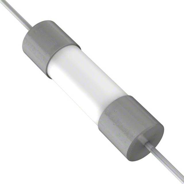
| 描述 | CURRENT LIMITER INRSH 5 OHM 20% |
| 产品分类 | 涌入电流限制器 (ICL) |
| 品牌 | EPCOS Inc |
| 数据手册 | |
| 产品图片 |
|
| 产品型号 | B57364S2509A2 |
| rohs | 无铅 / 符合限制有害物质指令(RoHS)规范要求 |
| 产品系列 | - |
| 不同电流时的R | - |
| 产品目录绘图 |
|
| 产品目录页面 | |
| 其它名称 | 495-4161 |
| 包装 | 散装 |
| 容差 | ±20% |
| 引线间距 | 0.295"(7.50mm) |
| 标准包装 | 1,000 |
| 电流-稳态(最大值) | 8.5A |
| 直径 | 0.825"(21mm) |
| 认可 | UL |



- 商务部:美国ITC正式对集成电路等产品启动337调查
- 曝三星4nm工艺存在良率问题 高通将骁龙8 Gen1或转产台积电
- 太阳诱电将投资9.5亿元在常州建新厂生产MLCC 预计2023年完工
- 英特尔发布欧洲新工厂建设计划 深化IDM 2.0 战略
- 台积电先进制程称霸业界 有大客户加持明年业绩稳了
- 达到5530亿美元!SIA预计今年全球半导体销售额将创下新高
- 英特尔拟将自动驾驶子公司Mobileye上市 估值或超500亿美元
- 三星加码芯片和SET,合并消费电子和移动部门,撤换高东真等 CEO
- 三星电子宣布重大人事变动 还合并消费电子和移动部门
- 海关总署:前11个月进口集成电路产品价值2.52万亿元 增长14.8%


PDF Datasheet 数据手册内容提取
NTC thermistors for inrush current limiting Leaded and coated disks Series/Type: B57364S0***M0** Date: November2015 ©EPCOSAG2015.Reproduction,publicationanddisseminationofthispublication,enclosuresheretoandthe informationcontainedthereinwithoutEPCOS'priorexpressconsentisprohibited. EPCOSAGisaTDKGroupCompany.
Inrushcurrentlimiters B57364S0***M0** ICLs S364 Applications Dimensionaldrawing Inrushcurrentlimiting,e.g.inswitch-modepower supplies,soft-startmotors Features LeadedandcoatedNTCthermistors Tinnedcopperwire,kinked CoatingmaterialflameretardanttoUL94V-0 Componentmarkingincludesthemanufacturer's logo,resistancevalueanddatecode Highlystableelectricalcharacteristics Approvals UL1434(filenumberE69802) IEC(certificatenumber101QA12) R =2upto10W 25 VDE(certificatenumber40038223) Dimensionsinmm R25=2upto10W Approx.weight4g CQC(0900104539) Options Resistancetolerance<20%andalternativelead configurationsavailableonrequest Deliverymode Bulk(standard),cardboardtapeonreelorAmmopack Generaltechnicaldata Climaticcategory (IEC60068-1) 55/170/21 Max.power (at25(cid:176) C) P 5.1 W max Resistancetolerance D R /R – 20 % R R Ratedtemperature T 25 (cid:176) C R Dissipationfactor (inair) d approx.24 mW/K th Thermalcoolingtimeconstant (inair) t approx.100 s c Heatcapacity C approx.2400 mJ/K th PleasereadCautionsandwarningsand Page2of20 Importantnotesattheendofthisdocument.
Inrushcurrentlimiters B57364S0***M0** ICLs S364 Electricalspecificationandorderingcodes R25 Imax Ctest1) Ctest1) Rmin Orderingcode (0...65(cid:176) C) 230VAC 110VAC (@Imax,25(cid:176) C) W A m F m F W 1 16 1000 4000 0.021 B57364S0109M0** 2 12 1000 4000 0.036 B57364S0209M0** 2.5 11 1000 4000 0.044 B57364S0259M0** 4 9.5 1000 4000 0.059 B57364S0409M0** 5 8.5 1000 4000 0.073 B57364S0509M0** 10 7.5 1000 4000 0.098 B57364S0100M0** **= Deliverymode 00= Bulk 51= Reelpacking 54= Ammopacking 1) FordetailsonthecapacitanceCtestpleasereferto"Applicationnotes",chapter1.6. PleasereadCautionsandwarningsand Page3of20 Importantnotesattheendofthisdocument.
Inrushcurrentlimiters B57364S0***M0** ICLs S364 Reliabilitydata Test Standard Testconditions D R /R Remarks 25 25 (typical) Storagein IEC Storageatupper <20% Novisible dryheat 60068-2-2 categorytemperature damage T:170(cid:176) C t:1000h Storageindamp IEC Temperatureofair:40(cid:176) C <20% Novisible heat,steadystate 60068-2-78 Relativehumidityofair:93% damage Duration:21days Thermalschock IEC Lowertesttemperature:(cid:4)55(cid:176) C <20% Novisible 60068-2-14 t:30min damage Uppertesttemperature:170(cid:176) C t:30min Timetochangefromlowerto uppertemperature:<30s Numberofcycles:10 Endurance IEC Ambienttemperature:25– 5(cid:176) C <20% Novisible 60539-1 I=I damage max t:1000h Cyclic IEC Ambienttemperature:25– 5(cid:176) C <20% Novisible endurance 60539-1 I=I damage max On-time=1min Coolingtime=5min Numberofcycles:1000 Maximum IEC Ambienttemperature:25– 5(cid:176) C <20% Novisible permissible 60539-1 Capacitance=C damage test capacitancetest Numberofcycles:1000 Note Theself-heatingofathermistorduringoperationdependsontheloadappliedandthe applicabledissipationfactor. Whenloadedwithmaximumallowablecurrent/powerandthespecifieddissipationfactoris takenasabasis,theNTCthermistormayreachameantemperatureofupto250(cid:176) C. Theheatdevelopedduringoperationwillalsobedissipatedthroughtheleadwires.Sothe contactareas,too,maybecomequitehotatmaximumload. WhenmountingNTCthermistorsyouhavetoensurethatthereisanadequatedistance betweenthethermistorandallpartswhicharesensitivetoheatorcombustible. PleasereadCautionsandwarningsand Page4of20 Importantnotesattheendofthisdocument.
Inrushcurrentlimiters B57364S0***M0** ICLs S364 Resistanceversustemperature S364series PleasereadCautionsandwarningsand Page5of20 Importantnotesattheendofthisdocument.
Inrushcurrentlimiters B57364S0***M0** ICLs S364 Resistanceversuscurrent S364series PleasereadCautionsandwarningsand Page6of20 Importantnotesattheendofthisdocument.
Inrushcurrentlimiters B57364S0***M0** ICLs S364 Applicationnotes ThefollowingtwoimportantaspectsfordeterminingtherightNTCinrushcurrentlimiterare excerptedfromthechapter"Applicationnotes"inthe"NTCInrushCurrentLimiters, Databook2012".Thecompleteapplicationnotecanbedownloadedfrom www.epcos.com/ntcicl_appnotes. 1.4Loadderating ThepowerhandlingcapabilityofanNTCthermistorcannotbefullyutilizedovertheentiretemper- aturerange.Forcircuitdimensioningthederatingcurvegivenbelowprovidesinformationonthe extenttowhichthecurrentmustbereducedatacertainambienttemperature(T ). A DeratingcurvefortypesS237,P11andP13 Figure1 T =Ambienttemperature>25(cid:176) C A T =170(cid:176) C max DeratingcurvefortypesS153,S235,S236,S238,S364andS464 Figure2 PleasereadCautionsandwarningsand Page7of20 Importantnotesattheendofthisdocument.
Inrushcurrentlimiters B57364S0***M0** ICLs S364 T =Ambienttemperature>65(cid:176) C A T =170(cid:176) C max TheI valuesspecifiedinthedatasheetsdenotethemaximumpermissiblecontinuouscurrent max (DCorRMSvaluesforsine-shapedAC)inthetemperaturerange0(cid:176) Cto65(cid:176) C. 1.6Maximumpermissiblecapacitance Thecurrentsduringturn-onaremuchhigherthantheratedcurrentsduringcontinuousoperation. TotesttheeffectsofthesecurrentsurgesEPCOSusesthefollowingstandardprocedureaccord- ingtoIEC60539-1: Figure3 TestcircuitforevaluatingthemaximumpermissiblecapacitanceofanNTCthermistor V Loadvoltage[V] load C Testcapacitance[m F] test R Seriesresistance[R =1W ] S S V VoltagedropacrosstheNTCundertest[V] NTC ThecapacitorC isdischargedviatheseriesresistorR andtheNTCinrushcurrentlimiter.The test S loadvoltageischosensuchthatthevoltageappliedtothethermistoratthestartofdischargeis VNTC=375V(correspondsto(230V+D V)(cid:5)(cid:6)2). PleasereadCautionsandwarningsand Page8of20 Importantnotesattheendofthisdocument.
Inrushcurrentlimiters B57364S0***M0** ICLs S364 Figure4 Maximumpermissiblecapacitancedischargingtest:typicalcurves The maximum capacitances that can be switched depend on the individual thermistor type and aregiveninthedatasheets. PleasereadCautionsandwarningsand Page9of20 Importantnotesattheendofthisdocument.
Inrushcurrentlimiters B57364S0***M0** ICLs S364 Tapingandpacking 1 TapingofradialleadedICLNTCthermistorsaccordingtothe specifiedleadspacing Dimensionsandtolerances LeadspacingF=5.0mm(tapingtoIEC60286-2) forthefollowingtypes:S153,S235andS236 LeadspacingF=7.5mm(tapingbasedonIEC60286-2) forthefollowingtypes:P11,P13,S237,S238andS364 PleasereadCautionsandwarningsand Page10of20 Importantnotesattheendofthisdocument.
Inrushcurrentlimiters B57364S0***M0** ICLs S364 Dimensions(mm) Lead Toleranceof Lead Toleranceof Remarks spacing leadspacing spacing leadspacing 5mm 5mm 7.5mm 7.5mm w £ 12.0 ‡ 12.0 pleaserefertodimensional drawings th 6.0 max. 7 max. pleaserefertodimensional drawings d 0.5/0.6 – 0.05 0.8/1.0 – 0.05 pleaserefertodimensional drawings P 12.7 – 0.3 12.7 – 0.3 – 1mm/20sprocketholes 0 P 3.85 – 0.7 8.95 – 0.8 1 F 5.0 +0.6/(cid:4)0.1 7.5 – 0.8 D h 0 – 2.0 0 Dependsonth measuredattop ofcomponentbody D p 0 – 1.3 0 – 2.0 W 18.0 – 0.5 18.0 – 0.5 W 5.5 min. 11.0 min. peel-offforce‡ 5N 0 W1 9.0 +0.75/(cid:4)0.5 9.0 +0.75/(cid:4)0.5 W 3.0 max. 3.0 max. 2 H 18.0 +2.0/(cid:4)0 18.0 +2.0/(cid:4)0 appliesonlytouncrimped types H 16.0 – 0.5 16.0 – 0.5 appliesonlytocrimpedtypes 0 H 32.2 max. 45.0 max. 1 D 4.0 – 0.2 4.0 – 0.2 0 t 0.9 max. 0.9 max. withoutwires L 11.0 max. 11.0 max. L 4.0 max. 4.0 max. 1 PleasereadCautionsandwarningsand Page11of20 Importantnotesattheendofthisdocument.
Inrushcurrentlimiters B57364S0***M0** ICLs S364 Typesofpacking Reelpacking Reeldimensions(inmm) Reeltype Series pcs.perreel d f n w I S153,S235 1500 360max. 31– 1 approx.45 54max. I S236 1000 360max. 31– 1 approx.45 54max. II P11,P13 1500 500max. 23– 1 approx.59 72max. II S237,S238,S364 1000 500max. 23– 1 approx.59 72max. Ammopacking Ammo Series pcs.per x y z type package I S153, 1000 45 335 272 S235, S236 II P11, 750 55 340 340 P13, S237, S238, S364 Ammopackingdimensions(inmm) Bulkpacking Thecomponentsarepackedincardboardboxes,thesizeofwhichdependsontheorderquantity. SeriesS464andP27isonlyavailableasbulk. PleasereadCautionsandwarningsand Page12of20 Importantnotesattheendofthisdocument.
Inrushcurrentlimiters B57364S0***M0** ICLs S364 Mountinginstructions 1 Soldering 1.1 LeadedNTCthermistors LeadedthermistorscomplywiththesolderabilityrequirementsspecifiedbyCECC. When soldering, care must be taken that the NTC thermistors are not damaged by excessive heat.Thefollowingmaximumtemperatures,maximumtimespansandminimumdistanceshave tobeobserved: Dipsoldering Ironsoldering Bathtemperature max.260(cid:176) C max.360(cid:176) C Solderingtime max.4s max.2s Distancefromthermistor min.6mm min.6mm Undermoreseveresolderingconditionstheresistancemaychange. Solderability(testtoIEC60068-2-20) Preconditioning:ImmersionintofluxF-SW32. Evaluationcriterion:Wettingofsolderingareas‡ 95%. Solder Bathtemperature((cid:176) C) Dwelltime(s) SnAg(3.0...4.0),Cu(0.5...0.9) 245– 3 3 1.1.1 Resistancetosolderingheat(testtoIEC60068-2-20) Preconditioning:ImmersionintofluxF-SW32. Solder Bathtemperature((cid:176) C) Dwelltime(s) SnAg(3.0...4.0),Cu(0.5...0.9) 260(cid:4)5 10 PleasereadCautionsandwarningsand Page13of20 Importantnotesattheendofthisdocument.
Inrushcurrentlimiters B57364S0***M0** ICLs S364 1.1.2 Wavesoldering Temperaturecharacteristicatcomponentterminalwithdualwavesoldering 2 Robustnessofterminations The leads meet the requirements of IEC 60068-2-21. They may not be bent closer than 4 mm from the solder joint on the thermistor body or from the point at which they leave the feed- throughs.Duringbending,anymechanicalstressattheoutletoftheleadsmustberemoved.The bendingradiusshouldbeatleast0.75mm. Tensilestrength: TestUa1: Leads 0.50< ˘£ 0.80mm= 10.0N 0.80< ˘£ 1.25mm= 20.0N Bendingstrength: TestUb: Two90(cid:176) -bendsinoppositedirectionsataweightof0.25kg. Torsionalstrength: TestUc:severity2 Theleadisbentby90(cid:176) atadistanceof6to6.5mmfromthethermistorbody. Thebendingradiusoftheleadsshouldbeapprox.0.75mm.Twotorsionsof 180(cid:176) each(severity2). PleasereadCautionsandwarningsand Page14of20 Importantnotesattheendofthisdocument.
Inrushcurrentlimiters B57364S0***M0** ICLs S364 Whensubjectingleadstomechanicalstress,thefollowingshouldbeobserved: Tensilestressonleads Duringmountingandoperationtensileforcesontheleadsaretobeavoided. Bendingofleads Bendingoftheleadsdirectlyonthethermistorbodyisnotpermissible. A lead may be bent at a minimum distance of twice the wire's diameter +2 mm from the solder jointonthethermistorbody.Duringbendingthewiremustbemechanicallyrelievedatitsoutlet. Thebendingradiusshouldbeatleast0.75mm. Twistingofleads Thetwisting(torsion)by180(cid:176) ofaleadbentby90(cid:176) ispermissibleat6mmfromthebottomofthe thermistorbody. 3 Sealingandpotting Whenthermistorsaresealed,pottedorovermolded,theremustbenomechanicalstresscaused by thermal expansion during the production process (curing / overmolding process) and during lateroperation.Theuppercategorytemperatureofthethermistormustnotbeexceeded.Ensure thatthematerialsused(sealing/pottingcompoundand plasticmaterial)arechemicallyneutral. 4 Cleaning If cleaning is necessary, mild cleaning agents such as ethyl alcohol and cleaning gasoline are recommended.Cleaningagentsbasedonwaterarenotallowed.Ultrasoniccleaningmethodsare permissible. 5 Storage Inordertomaintaintheirsolderability,thermistorsmustbestoredinanon-corrosiveatmosphere. Humidity,temperatureandcontainermaterialsarecriticalfactors. Thecomponentsshouldbeleftintheoriginalpacking.Touchingthemetallizationofunsoldered thermistorsmaychangetheirsolderingproperties. Storagetemperature: (cid:4)25(cid:176) Cupto45(cid:176) C Max.relativehumidity(withoutcondensation): <95%,maximum30daysperannum SolderthethermistorslistedinthisdatabookaftershipmentfromEPCOSwithinthetimespeci- fied: Leadedcomponents: 24months PleasereadCautionsandwarningsand Page15of20 Importantnotesattheendofthisdocument.
Inrushcurrentlimiters B57364S0***M0** ICLs S364 Cautionsandwarnings General See"Importantnotes"onpage2. Storage Storethermistorsonlyinoriginalpackaging.Donotopenthepackagebeforestorage. Storageconditionsinoriginalpackaging:storagetemperature(cid:4)25(cid:176) C...+45(cid:176) C,relative humidity£ 75%annualmean,maximum95%,dewprecipitationisinadmissible. Avoidcontaminationofthermistorssurfaceduringstorage,handlingandprocessing. Avoidstorageofthermistorinharmfulenvironmentslikecorrosivegases(SO,Cletc). x SolderthermistorsaftershipmentfromEPCOSwithinthetimespecified: (cid:4)Leadedcomponents:24months Handling NTCinrushcurrentlimitersmustnotbedropped.Chip-offsmustnotbecausedduringhandling ofNTCinrushcurrentlimiters. Componentsmustnotbetouchedwithbarehands.Glovesarerecommended. Avoidcontaminationofthermistorsurfaceduringhandling. IncaseofexposureoftheNTCinrushcurrentlimiterstowater,electrolytesorotheraggressive media,thesemediacanpenetratethecoatingandreachthesurfaceoftheceramic.Low-ohmic orhigh-ohmicbehaviormayoccurduetotheformationofanelectrolytewithmetals (silver/lead/tinfrommetallizationorsolder).Low-ohmicbehavioriscausedbyelectrochemical migration,high-ohmicbehaviorbydissolvingoftheelectrode.Ineithercase,thefunctionalityof theNTCinrushcurrentlimiterscannotbeassured. Washingprocessesmaydamagetheproductduetothepossiblestaticorcyclicmechanical loads(e.g.ultrasoniccleaning).Theymaycausecrackstodevelopontheproductanditsparts, whichmightleadtoreducedreliabilityorlifetime. Bending/twistingleads Alead(wire)maybebentataminimumdistanceoftwicethewire’sdiameterplus4mmfrom thecomponentheadorhousing.Whenbendingensurethewireismechanicallyrelievedatthe componentheadorhousing.Thebendingradiusshouldbeatleast0.75mm. Twisting(torsion)by180(cid:176) ofaleadbentby90(cid:176) ispermissibleat6mmfromthebottomofthe thermistorbody. Soldering Useresin-typefluxornon-activatedflux. Insufficientpreheatingmaycauseceramiccracks. Rapidcoolingbydippinginsolventisnotrecommended. Completeremovaloffluxisrecommended. PleasereadCautionsandwarningsand Page16of20 Importantnotesattheendofthisdocument.
Inrushcurrentlimiters B57364S0***M0** ICLs S364 Mounting WhenNTCinrushcurrentlimitersareencapsulatedwithsealingmaterialorovermoldedwith plasticmaterial,theprecautionsgiveninchapter“Mountinginstructions”,“Sealingandpotting” mustbeobserved. Electrodemustnotbescratchedbefore/during/afterthemountingprocess. Contactsandhousingsusedforassemblywiththermistorhavetobecleanbeforemounting. Duringoperation,theinrushcurrentlimiterssurfacetemperaturecanbeveryhigh.Ensurethat adjacentcomponentsareplacedatasufficientdistancefromthethermistortoallowforproper coolingoftheNTCinrushcurrentlimiters. Ensurethatadjacentmaterialsaredesignedforoperationattemperaturescomparabletothe surfacetemperatureofthethermistor.Besurethatsurroundingpartsandmaterialscan withstandthistemperature. Makesurethatinrushcurrentlimitersareadequatelyventilatedtoavoidoverheating. Avoidcontaminationofthermistorsurfaceduringprocessing. Operation UseNTCinrushcurrentlimitersonlywithinthespecifiedoperatingtemperaturerange. UseNTCinrushcurrentlimitersonlywithinthespecifiedvoltageandcurrentranges. EnvironmentalconditionsmustnotharmtheNTCinrushcurrentlimiters.UseNTCinrush currentlimitersonlyinnormalatmosphericconditions. ContactofNTCinrushcurrentlimiterswithanyliquidsandsolventsshouldbeprevented.It mustbeensuredthatnowaterenterstheNTCinrushcurrentlimiters(e.g.throughplug terminals).Formeasurementpurposes(checkingthespecifiedresistancevs.temperature),the componentmustnotbeimmersedinwaterbutinsuitableliquids(e.g.Galden). IncaseofexposureoftheNTCinrushcurrentlimiterstowater,electrolytesorotheraggressive media,thesemediacanpenetratethecoatingandreachthesurfaceoftheceramic.Low-ohmic orhigh-ohmicbehaviormayoccurduetotheformationofanelectrolytewithmetals (silver/lead/tinfrommetallizationorsolder).Low-ohmicbehavioriscausedbyelectrochemical migration,high-ohmicbehaviorbydissolvingoftheelectrode.Ineithercase,thefunctionalityof theNTCinrushcurrentlimiterscannotbeassured. Besuretoprovideanappropriatefail-safefunctiontopreventsecondaryproductdamage causedbymalfunction(e.g.useametaloxidevaristorforlimitationofovervoltagecondition). Thislistingdoesnotclaimtobecomplete,butmerelyreflectstheexperienceofEPCOSAG. DisplayoforderingcodesforEPCOSproducts TheorderingcodeforoneandthesameEPCOSproductcanberepresenteddifferentlyindata sheets,databooks,otherpublications,ontheEPCOSwebsite,orinorder-relateddocuments suchasshippingnotes,orderconfirmationsandproductlabels.Thevaryingrepresentationsof theorderingcodesareduetodifferentprocessesemployedanddonotaffectthe specificationsoftherespectiveproducts.DetailedinformationcanbefoundontheInternet underwww.epcos.com/orderingcodes PleasereadCautionsandwarningsand Page17of20 Importantnotesattheendofthisdocument.
Inrushcurrentlimiters B57364S0***M0** ICLs S364 Symbolsandterms Symbol English B Bvalue C Testcapacitance test C Heatcapacitance th I Current I Maximumcurrentwithinstatedtemperaturerange max I NTCcurrent NTC I Hightestcurrentforadditionalendurancetests test P Maximumpowerwithinstatedtemperaturerange max R Minimumresistance min R Ratedresistance R D R /R Resistancetolerance R R R Seriesresistance S R ResistanceattemperatureT T (e.g.R =resistanceat25(cid:176) C) 25 T Temperature t Time T Ambienttemperature A t Thermalthresholdtime a T Uppercategorytemperature max T Lowercategorytemperature min T Ratedtemperature R V Voltage V Loadvoltage load V VoltagedropacrossanNTCthermistor NTC a Temperaturecoefficient D Tolerance,change d Dissipationfactor th t Thermalcoolingtimeconstant c Abbreviations/Notes Symbol English * Tobereplacedbyanumberinorderingcodes,typedesignationsetc. + Tobereplacedbyaletter. Alldimensionsaregiveninmm. Thecommasusedinnumericalvaluesdenotedecimalpoints. PleasereadCautionsandwarningsand Page18of20 Importantnotesattheendofthisdocument.
Importantnotes The following applies toall products named in this publication: 1. Some parts of this publication contain statements about the suitability of our products for certain areas of application. These statements are based on our knowledge of typical requirements that are often placed on our products in the areas of application concerned. We nevertheless expressly point out that such statements cannot be regarded as binding statements about the suitability of our products for a particular customer application. As a rule we are either unfamiliar with individual customer applications or less familiar with them than the customers themselves. For these reasons, it is always ultimately incumbent on the customer to check and decide whether a product with the properties described in the product specification is suitable for use in a particular customer application. 2. We also point out that in individual cases, a malfunction of electronic components or failure before the end of their usual service life cannot be completely ruled out in the current state of the art, even if they are operated as specified. In customer applications requiring a very high level of operational safety and especially in customer applications in which the malfunction or failure of an electronic component could endanger human life or health (e.g. in accident prevention or life-saving systems), it must therefore be ensured by means of suitable design of the customer application or other action taken by the customer (e.g. installation of protective circuitry or redundancy) that no injury or damage is sustained by third parties in the event of malfunction or failure of an electronic component. 3. The warnings, cautions and product-specific notes must be observed. 4. In order to satisfy certain technical requirements, some of the products described in this publication may contain substances subject to restrictions in certain jurisdictions (e.g. because they are classed as hazardous). Useful information on this will be found in our Material Data Sheets on the Internet (www.tdk-electronics.tdk.com/material). Should you have any more detailed questions, please contact our sales offices. 5. We constantly strive to improve our products. Consequently, the products described in this publication may change from time to time. The same is true of the corresponding product specifications. Please check therefore to what extent product descriptions and specifications contained in this publication are still applicable before or when you place an order. We also reserve the right to discontinue production and delivery of products. Consequently, we cannot guarantee that all products named in this publication will always be available. The aforementioned does not apply in the case of individual agreements deviating from the foregoing for customer-specific products. 6. Unless otherwise agreed in individual contracts, all orders are subject to our General Terms and Conditions of Supply. 7. Our manufacturing sites serving the automotive business apply the IATF 16949 standard. The IATF certifications confirm our compliance with requirements regarding the quality management system in the automotive industry. Referring to customer requirements and customer specific requirements (“CSR”) TDK always has and will continue to have the policy of respecting individual agreements. Even if IATF 16949 may appear to support the acceptance of unilateral requirements, we hereby like to emphasize that only requirements mutually agreed upon can and will be implemented in our Quality Management System. For clarification purposes we like to point out that obligations from IATF 16949 shall only become legally binding if individually agreed upon. Page19of20
Importantnotes 8. The trade names EPCOS, CeraCharge, CeraDiode, CeraLink, CeraPad, CeraPlas, CSMP, CTVS, DeltaCap, DigiSiMic, ExoCore, FilterCap, FormFit, LeaXield, MiniBlue, MiniCell, MKD, MKK, MotorCap, PCC, PhaseCap, PhaseCube, PhaseMod, PhiCap, PowerHap, PQSine, PQvar, SIFERRIT, SIFI, SIKOREL, SilverCap, SIMDAD, SiMic, SIMID, SineFormer, SIOV, ThermoFuse, WindCap are trademarks registered or pending in Europe and in other countries. Further information will be found on the Internet at www.tdk-electronics.tdk.com/trademarks. Release 2018-10 Page20of20
/B57364S2509A2.jpg)
 Datasheet下载

