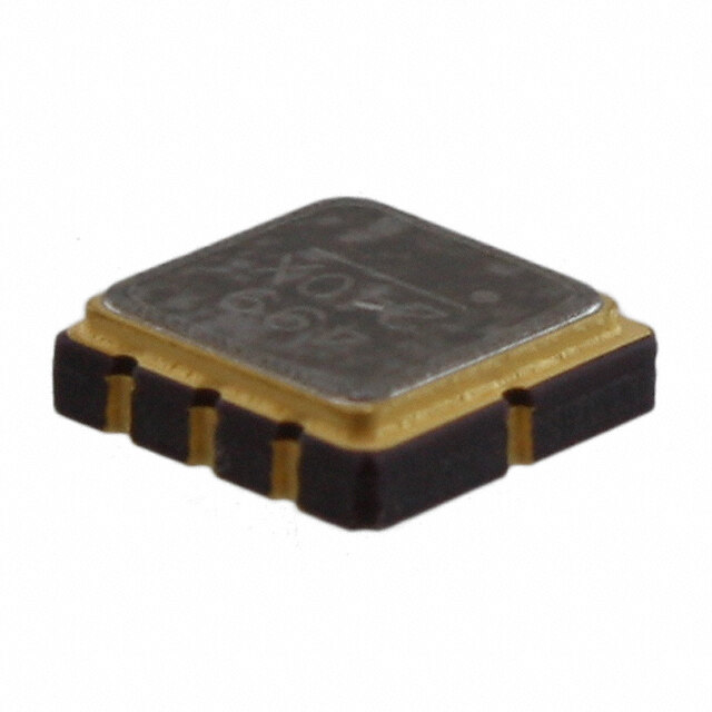
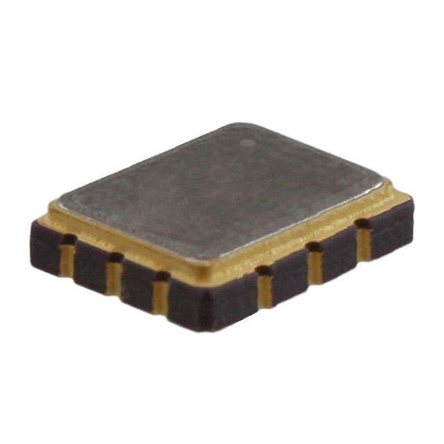
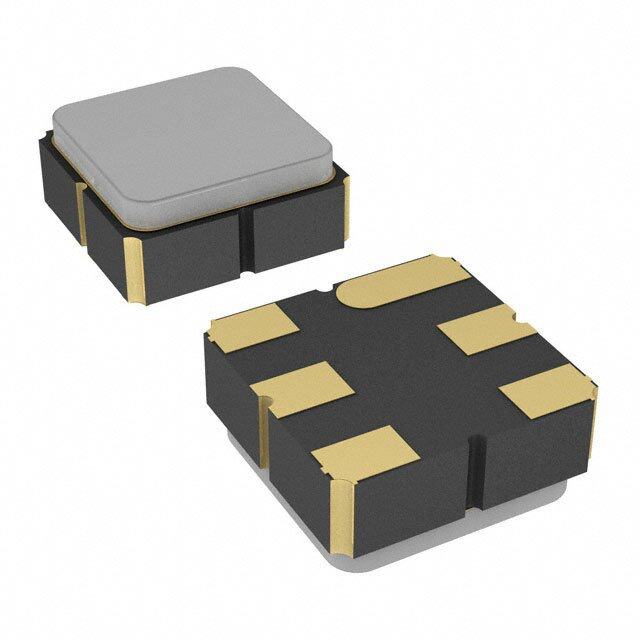
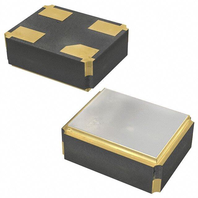
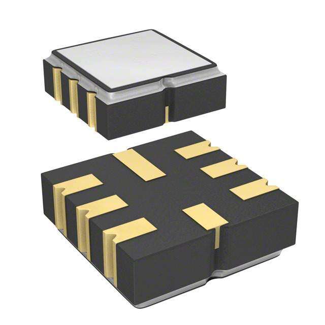
- 型号: B39451B3767Z810
- 制造商: EPCOS
- 库位|库存: xxxx|xxxx
- 要求:
| 数量阶梯 | 香港交货 | 国内含税 |
| +xxxx | $xxxx | ¥xxxx |
查看当月历史价格
查看今年历史价格
B39451B3767Z810产品简介:
ICGOO电子元器件商城为您提供B39451B3767Z810由EPCOS设计生产,在icgoo商城现货销售,并且可以通过原厂、代理商等渠道进行代购。 B39451B3767Z810价格参考。EPCOSB39451B3767Z810封装/规格:SAW 滤波器, 。您可以下载B39451B3767Z810参考资料、Datasheet数据手册功能说明书,资料中有B39451B3767Z810 详细功能的应用电路图电压和使用方法及教程。
| 参数 | 数值 |
| 产品目录 | |
| 描述 | FILTER SAW 447.725MHZ SMD |
| 产品分类 | |
| 品牌 | EPCOS Inc |
| 数据手册 | |
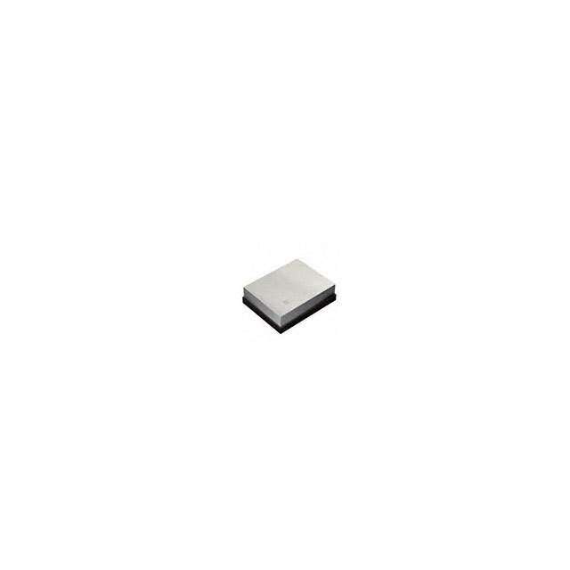
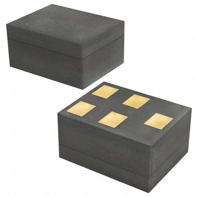
| 产品图片 |
|
| 产品型号 | B39451B3767Z810 |
| rohs | 无铅 / 符合限制有害物质指令(RoHS)规范要求 |
| 产品系列 | - |
| 其它名称 | 495-3740-1 |
| 包装 | 剪切带 (CT) |
| 大小/尺寸 | 0.150" 长 x 0.150" 宽(3.80mm x 3.80mm) |
| 安装类型 | 表面贴装 |
| 封装/外壳 | 8-SMD,无引线 |
| 带宽 | 360kHz |
| 应用 | 远程控制 |
| 插入损耗 | 1.9dB |
| 标准包装 | 1 |
| 滤波器类型 | 带通 |
| 频率 | 447.725MHz 中心 |
| 高度(最大值) | 0.059"(1.50mm) |


- 商务部:美国ITC正式对集成电路等产品启动337调查
- 曝三星4nm工艺存在良率问题 高通将骁龙8 Gen1或转产台积电
- 太阳诱电将投资9.5亿元在常州建新厂生产MLCC 预计2023年完工
- 英特尔发布欧洲新工厂建设计划 深化IDM 2.0 战略
- 台积电先进制程称霸业界 有大客户加持明年业绩稳了
- 达到5530亿美元!SIA预计今年全球半导体销售额将创下新高
- 英特尔拟将自动驾驶子公司Mobileye上市 估值或超500亿美元
- 三星加码芯片和SET,合并消费电子和移动部门,撤换高东真等 CEO
- 三星电子宣布重大人事变动 还合并消费电子和移动部门
- 海关总署:前11个月进口集成电路产品价值2.52万亿元 增长14.8%


PDF Datasheet 数据手册内容提取
SAW Components Data Sheet B3767
SAW Components B3767 Low-loss Filter 447,725 MHz Data Sheet Ceramic package QCC8B Features n RF low-loss filter for remote control receivers n Package for Surface Mounted Technology (SMT) n Balanced and unbalanced operation possible n Protection layer: Elpas n AEC-Q200 qualified component family Terminals n Ni, gold plated typ. dimensions in mm, approx. weight 0,07 g Pin configuration1) 1 Input Ground (recommended) or Input 2 Input (recommended) or Input Ground 5 Output (recommended) or Output Ground 6 Output Ground (recommended) or Output 4,8 Case - Ground 3,7 to be grounded Type Ordering code Marking and package Packing according to according to B3767 B39451-B3767-Z810 C61157-A7-A46 F61074-V8167-Z000 ElectrostacticSensitiveDevice (ESD) Maximum ratings Operable temperature range T –45/+120 ˚C A Storage temperature range T –45/+120 ˚C stg DC voltage V 6 V DC Source power P 10 dBm source impedance 50 W S 1)The recommended pin configuration usually offers best suppression of electrical crosstalk.The filter characteristics refer to this configuration. 2 Nov 24, 2004
SAW Components B3767 Low-loss Filter 447,725 MHz Data Sheet Characteristics Reference temperature: T = –40 ... +95˚C A Terminating source impedance: Z = 50W and matching network S Terminating load impedance: Z = 50W and matching network L min. typ. max. Center frequency fC — 447,725 — MHz (center frequency between 3 dB points) Minimum insertion attenuation a min including loss in matching elements — 1,9 2,7 dB excluding loss in matching elements — 1,4 2,2 dB Pass band(relative toa ) min 447,60 ... 447,85 MHz — 0,5 2,0 dB 447,58 ... 447,87 MHz — 0,7 3,0 dB 447,56 ... 447,91 MHz — 1,0 6,0 dB Filter bandwidth a £ 3 dB 0,61 0,67 0,73 MHz rel Relative attenuation(relative toa ) a min rel 10,00 ... 427,80 MHz 51 55 — dB 427,80 ... 437,30 MHz 47 51 — dB 437,30 ... 445,52 MHz 29 34 — dB 445,52 ... 445,92 MHz 22 27 — dB 445,92 ... 446,90 MHz 17 21 — dB 448,72 ... 455,80 MHz 18 21 — dB 455,80 ... 500,00 MHz 39 44 — dB 500,00 ... 720,00 MHz 50 55 — dB 720,00 ... 830,00 MHz 45 50 — dB 830,00 ...1000,00 MHz 60 65 — dB 1000,00 ...2500,00 MHz 45 50 — dB Impedancefor pass band matching1) Input: Z =R ||C — 240 ||2,2 — W || pF IN IN IN Output:ZOUT =ROUT ||COUT — 240 ||2,2 — W || pF 1)Impedance for passband matching bases on an ideal, perfect matching of the SAW filter to source-andtoloadimpedance(here50Ohm). AftertheSAWfilterisremovedandinput imped- ance into the input matching / output matching network is calculated. Theconjugatecomplex valueofthesecharacteristicimpedancesaretheinputandoutput imped- ances for flat passband. For more details, we refer to EPCOS application note #4. 3 Nov 24, 2004
SAW Components B3767 Low-loss Filter 447,725 MHz Data Sheet Matching network to 50W (element values depend on pcb layout and equivalent circuit) C = 1,5 pF p1 L = 33 nH s2 L = 33 nH s3 C = 1,5 pF p4 Minimising the crosstalk Foragoodultimaterejectionalowcrosstalkisnecessary.Lowcrosstalkcanberealisedwith a good RF layout. The major crosstalk mechanism is caused by the “ground-loop” problem. Groundingloopsarecreatedifinput-andoutputtransducerGNDareconnectedonthetop-side ofthePCBandfedtothesystemgroundingplanebyacommonviahole.Toavoidthecommon groundpath,thegroundpinoftheinput-andoutputtransducerarefedtothesystemground plane (bottom PCB plane) by their own via hole. The transducers’ grounding pins should be isolated from the upper grounding plane. A common GND inductivity of 0.5nH degrades the ultimate rejection (crosstalk) by 20dB. TheoptimisedPCBlayout,includingmatchingnetworkfortransformationto50Ohm,isshown here.InthisPCBlayoutthegroundingloopsareminimisedtorealise goodultimaterejection. Optimised PCB layout for SAW filters in QCC8B package, pinning 2,5 (top side, scale 1:1) Thebottomsideisacopperplane(systemgroundarea).Theinputandoutputgroundingpins are isolated and connected to the common ground by separated via holes. For good contact of the upper grounding area with the lower side it is necessary to place enough via holes. 4 Nov 24, 2004
SAW Components B3767 Low-loss Filter 447,725 MHz Data Sheet Frequency response Frequency response(wideband) 5 Nov 24, 2004
SAW Components B3767 Low-loss Filter 447,725 MHz Data Sheet Frequency response(ultimate rejection) Published by EPCOS AG Surface Acoustic Wave Components Division, SAW CE AE PD P.O. Box 80 17 09, D-81617 München ª EPCOSAG2004.AllRightsReserved.Reproduction,publicationanddisseminationofthisbro- chure and the information contained therein without EPCOS’ prior express consent is prohibited. Theinformationcontainedinthisbrochuredescribesthetypeofcomponentandshallnotbecon- sidered as guaranteed characteristics. Purchase orders are subject to the General Conditions for theSupplyofProductsandServicesoftheElectricalandElectronicsIndustryrecommendedbythe ZVEI (German Electrical and Electronic Manufacturers’ Association), unless otherwise agreed. This brochure replaces the previous edition. Forquestionsontechnology,pricesanddeliverypleasecontacttheSalesOfficesofEPCOSAGor the international Representatives. Duetotechnicalrequirementscomponentsmaycontaindangeroussubstances.Forinformationon the type in question please also contact one of our Sales Offices. 6 Nov 24, 2004
Mouser Electronics Authorized Distributor Click to View Pricing, Inventory, Delivery & Lifecycle Information: E PCOS: B39451B3767Z810
 Datasheet下载
