ICGOO在线商城 > AT4036F
- 型号: AT4036F
- 制造商: NKK Switches
- 库位|库存: xxxx|xxxx
- 要求:
| 数量阶梯 | 香港交货 | 国内含税 |
| +xxxx | $xxxx | ¥xxxx |
查看当月历史价格
查看今年历史价格
AT4036F产品简介:
ICGOO电子元器件商城为您提供AT4036F由NKK Switches设计生产,在icgoo商城现货销售,并且可以通过原厂、代理商等渠道进行代购。 提供AT4036F价格参考以及NKK SwitchesAT4036F封装/规格参数等产品信息。 你可以下载AT4036F参考资料、Datasheet数据手册功能说明书, 资料中有AT4036F详细功能的应用电路图电压和使用方法及教程。
| 参数 | 数值 |
| 产品目录 | |
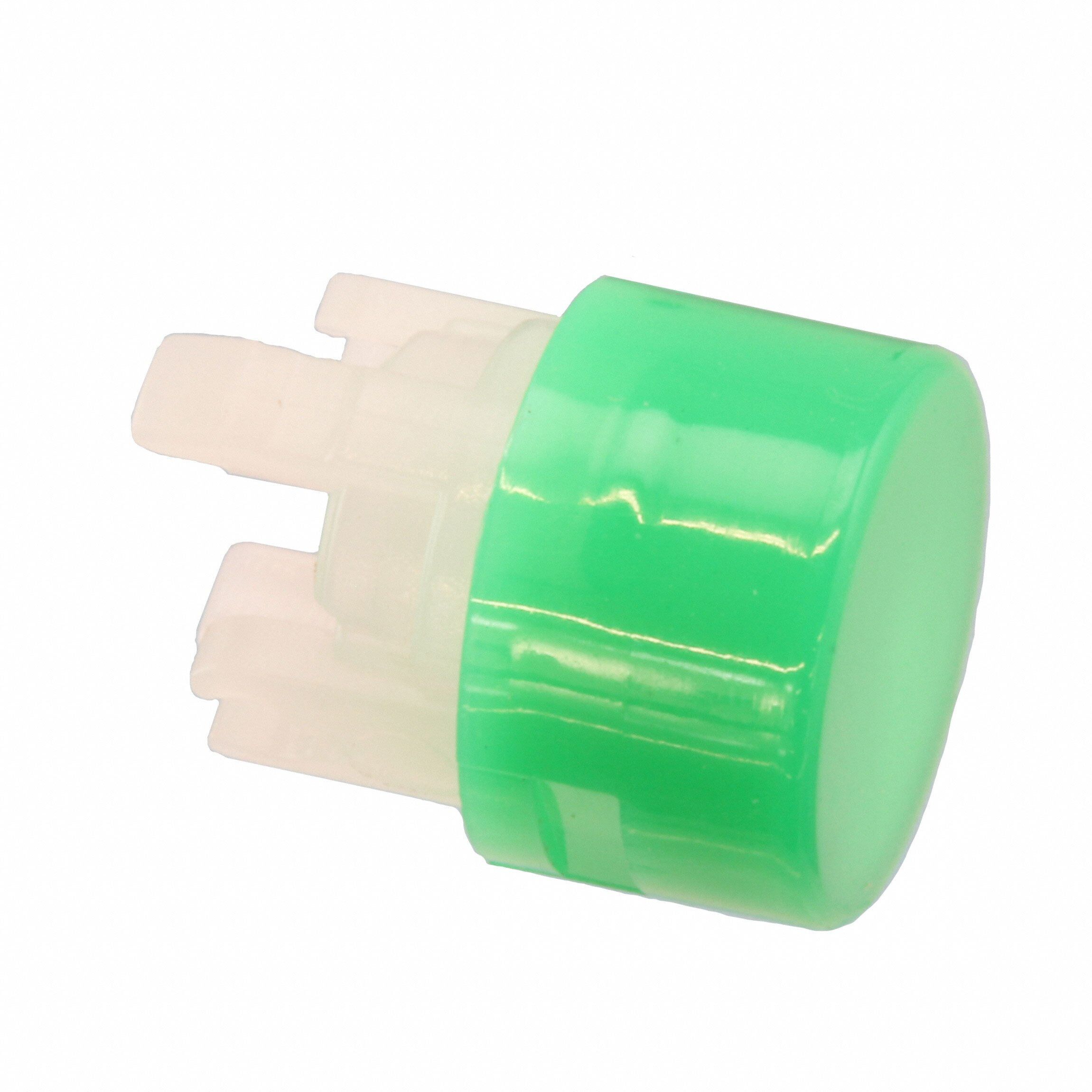
| 描述 | CAP PUSHBUTTON ROUND GREEN开关翘板/开关帽 ROUND GREEN CAP FOR HB NONILLUMINATED |
| 产品分类 | |
| 品牌 | NKK Switches |
| 产品手册 | |
| 产品图片 |
|
| rohs | 符合RoHS无铅 / 符合限制有害物质指令(RoHS)规范要求 |
| 产品系列 | 开关配件,开关翘板/开关帽,NKK Switches AT4036FHB |
| 数据手册 | |
| 产品型号 | AT4036F |
| 产品 | Caps |
| 产品培训模块 | http://www.digikey.cn/PTM/IndividualPTM.page?site=cn&lang=zhs&ptm=7079 |
| 产品种类 | 开关翘板/开关帽 |
| 商标 | NKK Switches |
| 安装类型 | 卡入式 |
| 尺寸 | 7.40mm 直径 x 4.50mm 高 |
| 工厂包装数量 | 1 |
| 开关类型 | 按钮 |
| 形状 | 圆形 |
| 材料 | Polycarbonate (PC) |
| 标准包装 | 1 |
| 照明 | 不发光 |
| 特性 | - |
| 用于 | Pushbutton Switches, Miniature |
| 端接类型 | Snap On |
| 类型 | Button |
| 系列 | AT |
| 设计目的 | HB Series |
| 配套使用产品/相关产品 | HB 系列 |
| 长度 | 7.4 mm |
| 零件号别名 | AT-4036-M |
| 颜色 | Green |
| 高度 | 4.5 mm |

PDF Datasheet 数据手册内容提取
Series HB Subminiature Pushbuttons s e gl g General Specifications o T s er k c o Electrical Capacity (Resistive Load) R Power Level (silver): 0.1A maximum @ 30V AC/DC s n o butt Other Ratings h us Contact Resistance: 50 milliohms maximum P Insulation Resistance: 100 megohms minimum @ 500V DC B d P Dielectric Strength: 500V AC minimum for 1 minute minimum ateD Mechanical Life: 100,000 operations minimum n mi Electrical Life: 50,000 operations minimum u Ill Nominal Operating Force: 3.43N ble Contact Timing: Nonshorting (break before make) ma Travel: Pretravel .087” (2.2mm); Overtravel .031” (0.8mm); Total Travel .118” (3.0mm) m a gr o Pr Materials & Finishes s Housing: Glass fiber reinforced polyamide k oc Base: Glass fiber reinforced polyamide yl e Movable Contact: Phosphor bronze with silver plating K Stationary Contacts: Phosphor bronze with silver plating Common Terminal: Phosphor bronze with silver plating s e End Terminals: Phosphor bronze with silver plating otari Lamp Terminals: Phosphor bronze with silver plating R Environmental Data s de Operating Temperature Range: –25°C through +50°C (–13°F through +122°F) for Illuminated Sli –25°C through +70°C (–13°F through +158°F) for Nonilluminated Humidity: 90 ~ 95% humidity for 96 hours @ 40°C (104°F) Vibration: 10 ~ 55Hz with peak-to-peak amplitude of 1.5mm traversing the frequency range & returning es in 1 minute; 3 right angled directions for 2 hours actil Shock: 50G (490m/s2) acceleration (tested in 6 right angled directions, with 5 shocks in each direction) T Installation Tilt Mounting Torque: 0.49Nm (4.34 lb•in) maximum for round mounting nut Cap Installation Force: 9.8N (2.2 lbf) maximum downward force on cap Soldering Time & Temperature: Manual Soldering: See Profile A in Supplement section. h c u Standards & Certifications o T UL: File No. E44145 - Recognized only when ordered with marking on switch. Add “/U” or “/CUL” before first dash in part number to order UL recognized switch. ors All models recognized at 0.1A @ 30V AC/DC. at c di n I s e ori s s e c c A nt e m e pl p u S D12 www.nkkswitches.com
Series HB Subminiature Pushbuttons s e gl Distinctive Characteristics g o T s er k c o R Full face and spot illumination available. Front panel relamping. s n o Choice of super bright LEDs in white, green, and blue in utt b h addition to bright red, amber, and green LEDs. s u P B P Compact front panel design with 9mm square or round ed D at bezel options. min u Ill e Rear panel threaded mounting. Behind panel depth of bl a m less than one inch. 8mm body diameter fits common m a size panel cutout. gr o Pr s Latchdown feature gives indication of circuit status. Audible ck o and tactile feedback with smooth and responsive operation. yl e K Dual, sliding contacts with self-cleaning action provide s e contact stability, high reliability, and increased operating life. ari ot R Solder lug terminals have spacing of .100” (2.54mm) for choice of mounting. es d Sli Longer normally closed terminal facilitates wiring and soldering. s e Molded-in terminals lock out flux, dust, and other contaminants. ctil a T Matching indicators available. Tilt h c u o T Actual Size s or at c di n I s e ori s s e c c A nt e m e pl p u S www.nkkswitches.com D13
Series HB Subminiature Pushbuttons s e gl TYPICAL SWITCH ORDERING EXAMPLE g o T HB 1 5 S K W01 6G JB s er k c o R s n o utt Pole Shapes Contacts & Terminals b sh 1 SPDT S Square Silver Contacts and u P W01 Solder Lug Terminals C Round B 0.1A @ 30V AC/DC P d e atD n mi u Ill e Circuits Housing LEDs Cap Types & Colors bl a mm 5 ON (ON) K Black only a Bright LED Cap: Lens/Diffuser Color gr ( ) = Momentary Pro 5C Red AB Black Cap/White Window for 6 ON ON Spot Illuminated (Square only) 5D Amber s ock Alternate Action 5F Green CB Red/White yl with Latchdown e DB Amber/White K FB Green/White s JB Clear/White e ari ot R IMPORTANT: Super Bright LED Cap: Lens/Diffuser Color Switches are supplied without UL & cULus marking 6B White JB Clear/White unless specified. UL & cULus recognized only when s 6F Green de ordered with marking on the switch. Specific models, Sli ratings, & ordering instructions are noted on the 6G Blue General Specifications page. Nonilluminated Nonilluminated Cap Colors s e ctil No Nonilluminated A Black (Square Only) a Code T B White C Red E Yellow Tilt F Green G Blue h c u o T DESCRIPTION FOR TYPICAL ORDERING EXAMPLE HB15SKW01-6G-JB s or at c di Blue, Super Bright LED White Cap n I Square Shape s e ori ss Black Housing e cc SPDT A ON-(ON) Circuit Silver Contacts & ent Solder Lug Terminals; m e rated 0.1A @ 30V AC/DC pl p u S D14 www.nkkswitches.com
Series HB Subminiature Pushbuttons s e POLES & CIRCUITS gl g o T Plunger Position ( ) = Momentary Connected Terminals Throw & Switch/Lamp Schematics s er Normal Down Normal Down Notes: Switch is marked with NO, NC, C, L. ock Pole Model LED circuit is isolated and requires R external power source. s n o HB15 ON (ON) 1(COM) butt SP *HB16 ON ON 1-3 1-2 SPDT 3 2 (+) (-) Push B * When in latchdown position for the alternate circuit, cap position is .051” (1.3mm) above the built-in bezel. d P e D at n mi u SHAPES & PANEL CUTOUT Ill e bl a m m S .354” (9.0mm) Square C .354” (9.0mm) Round ogra Pr s k c o yl e K The bezel is an integral The bezel is an integral part of the switch body. part of the switch body. s e ari Panel Cutout & Mounting Rot s e d Sli Recommended Panel Thickness: Overtightening the mounting nut AT073 .020 ~ .197” (0.5 ~ 5.0mm) may damage the switch housing. (8.0) Dia .315 es ctil a T HOUSING Tilt K Housing available in black only. h c u CONTACT MATERIALS, RATINGS, & TERMINALS To W01 s Silver Contacts Power Level 0.1A maximum @ 30V AC/DC or at c di n I Solder Lug PCB Mounting s e (2.0) (.519.07) Solder lug terminals are spaced essori .079 (1.8) .100” x .200” (2.54mm x 5.08mm). cc .071 A (1.0) This enables PCB mounting which can be .039 Thk = (0.3) accomplished by elongating PC board nt .012 holes to .080” (2.03mm). me e pl p u S www.nkkswitches.com D15
Series HB Subminiature Pushbuttons s e gl LED COLORS & SPECIFICATIONS g o T The electrical specifications shown are determined at a basic temperature of 25°C. LED circuit is isolated and requires external power source. Single element LED is colored in OFF state. s If the source voltage exceeds the rated voltage, a ballast resistor is required. er k The resistor value can be calculated by using the formula in the Supplement section. c o R Bright Bright Super Bright ATTENTION ns AT633 Note for Super Bright: ELECTROSTATIC o SENSITIVE DEVICES utt 5C 5D 5F 6B 6F 6G b h s Pu Super Bright (+) (-) Color Red Amber Green White Green Blue Unit PB AT624G Maximum Forward Current I 30 30 30 30 30 30 mA d FM ateD Blue Typical Forward Current I 20 20 20 20 20 20 mA n F mi AT629B u Forward Voltage V 1.95 2.0 2.1 3.3 3.3 3.3 V Ill White F e Maximum Reverse Voltage V 5 5 5 7 7 7 V abl AT630F RM m m Green Current Reduction Rate Above 25°C ∆I 0.42 0.42 0.42 0.40 0.40 0.40 mA/°C a F ogr T-1 Bi-pin Ambient Temperature Range –25° ~ +50°C –25° ~ +50°C Pr No Code s k No Lamp c o yl Ke CAP TYPES & COLORS Color Codes: A Black B White C Red D Amber E Yellow F Green G Blue J Clear s e Rotari Cap Colors Available: Colored Cap for Bright LEDs (.72.941) Sq .(017.81) (1.2) AB Black Cap with Translucent Square only AT4052 (4.8)(.418.61) .047(3.0) White Window for LED Display Material: Polycarbonate Spot Illuminated .189 .118 s e d Finish: Matte Sli Lens/Diffuser AT4166 AT4167 Transparent Colored Colors Available: Square Round Lens s (7.4) Sq (7.4) Dia Tactile CB Red/White .291(.417.57) .29(.4117.57) Translucent DB Amber/White (.418.89) (.418.89) White Diffuser Tilt FB Green/White Material: Polycarbonate Finish: Glossy CATo6lo3r3ed LED White Cap for Bright & Super Bright LEDs Transparent Clear Lens ch JB Clear Lens/ u White Diffuser AT4031 AT4032 o T Square (7.4) Sq Round (7.4) Dia Translucent .291 .291 White Diffuser cators MFinaitsehr:i aGl:l oPsoslyycarbonate (.418.89) (.417.57) (.418.89) (.417.57) CATo6lo2r4ed, ALTE6D2s9, di AT630, or AT633 n I s Nonilluminated Caps e ori Cap Colors Available: ss AT4035 AT4036 e cc A Black C F Square (7.4) Sq Round (7.4) Dia A (Square Only) Red Green .291 .291 (4.5) (4.5) ement B White E Yellow G Blue (.418.89) .177 (.418.89) .177 pl p Material: Polycarbonate Finish: Glossy u S D16 www.nkkswitches.com
Series HB Subminiature Pushbuttons s e TYPICAL SWITCH DIMENSIONS gl g o T Single Pole Square s M8P0.75 .(013.09) xx (.20.709) Typ L(+) L(-) cker (0.3) Typ (2.54) Typ o .012 NO 2 .100 R NC 3 (1.8) COM 1 s (.519.07) .(002.50) .071 utton .(72.941) Sq .(01.531) (.1309.04) (.519.07) shb u (9.0) Sq (3.5) (5.3) (15.5) (7.0) (2.54) Typ P .354 .138 .209 .610 .276 .100 Latchdown Position PB d e D at HB15SKW01-5C-CB n mi u Single Pole Round Ill e bl a m m M8P0.75 .(013.09) xx (.20.709) Typ L(+) L(-) gra (.00.132) Typ NO 2 ( 2.1.0504) Typ Pro NC 3 (1.8) COM 1 ks .071 oc (.519.07) .(002.50) eyl (7.4) Dia (1.3) (10.0) (5.0) K .291 .051 .394 .197 (9.0) Dia (3.5) (5.3) (15.5) (7.0) (2.54) Typ .354 .138 .209 .610 .276 .100 Latchdown Position es ari HB16CKW01-5C-CB ot R ASSEMBLY INSTRUCTIONS s e d Cap Removal LED Polarity & Orientation in Lamp Socket Cap Replacement Sli 1. Have cap in extended For AT624, AT629, AT630: Insert the LED with the 1. Match the prongs on position (not latchdown) for D flat opposite the black dot molded inside the the cap base with the es alternate action models. switch lamp socket. For AT633: Insert the LED with projections in the switch, ctil a the Black Dot on the terminal to the right. at the same time aligning T 2. Use the grip slots on the the spring clips on the sides of the cap and pull it cap with the indentations out of the switch. D Flat D Flat in the switch. Tilt (+) (+) AT624 (–) (–) AT633 2. Press firmly in place. AT629 AT630 Top View of Switch h c u Anode Cathode To (+) (–) s or at SEENLASETCITTTIEVRNEO TSDITOEAVTNIICCES S&u ApTe6r 3B0ri gahrte LeElDecst rAoTs6ta2ti4c, sAeTn6si2ti9ve, . Indic s e ori s s e AT111 Lamping Tool AT110 Socket Wrench cc A Lamping Tool AT111 may be Socket Wrench AT110 may be nt e used to remove and replace LED. used to tighten the mounting nut. m e pl p u S www.nkkswitches.com D17
 Datasheet下载


