- 型号: AQ2A2-C1-ZT12VDC
- 制造商: Panasonic Corporation
- 库位|库存: xxxx|xxxx
- 要求:
| 数量阶梯 | 香港交货 | 国内含税 |
| +xxxx | $xxxx | ¥xxxx |
查看当月历史价格
查看今年历史价格
AQ2A2-C1-ZT12VDC产品简介:
ICGOO电子元器件商城为您提供AQ2A2-C1-ZT12VDC由Panasonic Corporation设计生产,在icgoo商城现货销售,并且可以通过原厂、代理商等渠道进行代购。 AQ2A2-C1-ZT12VDC价格参考。Panasonic CorporationAQ2A2-C1-ZT12VDC封装/规格:固态继电器, 固体继电器 继电器 SPST-NO(1 Form A) 4-SIP。您可以下载AQ2A2-C1-ZT12VDC参考资料、Datasheet数据手册功能说明书,资料中有AQ2A2-C1-ZT12VDC 详细功能的应用电路图电压和使用方法及教程。
| 参数 | 数值 |
| 产品目录 | |
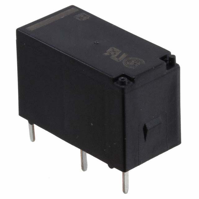
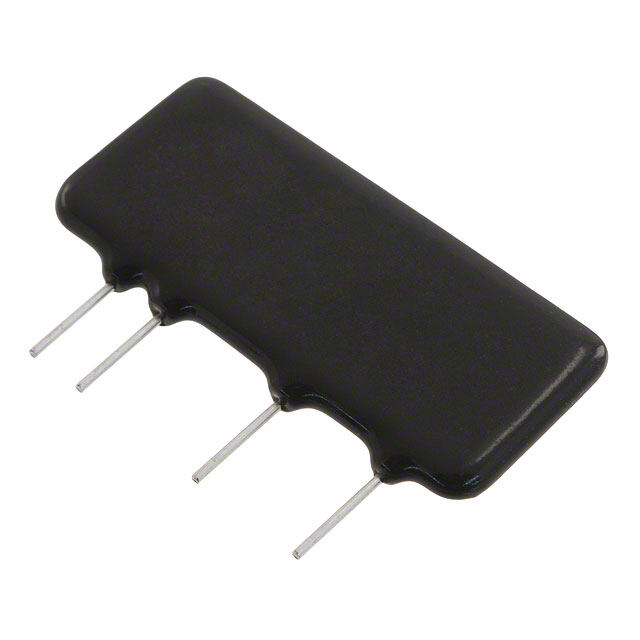
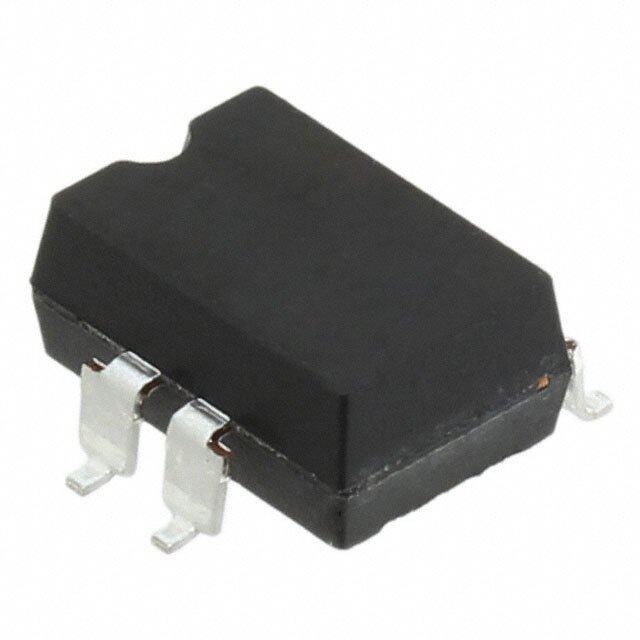
| 描述 | RELAY SSR ZERO-X 12VDC SIP固态继电器-PCB安装 2A 12VDC Zero Cross |
| 产品分类 | |
| 品牌 | Panasonic Electric Works |
| 产品手册 | |
| 产品图片 |
|
| rohs | 符合RoHS含铅 / 不符合限制有害物质指令(RoHS)规范要求 |
| 产品系列 | 固态继电器,固态继电器-PCB安装,Panasonic Industrial Devices AQ2A2-C1-ZT12VDCAQ8 |
| 数据手册 | |
| 产品型号 | AQ2A2-C1-ZT12VDC |
| 产品 | Automation Relays |
| 产品目录绘图 |
|
| 产品种类 | 固态继电器-PCB安装 |
| 产品类型 | PCB Mount |
| 供应商器件封装 | 4-SIL |
| 其它名称 | 255-1169 |
| 其它有关文件 | |
| 包装 | 散装 |
| 商标 | Panasonic Industrial Devices |
| 安装类型 | 通孔 |
| 安装风格 | Through Hole |
| 导通电阻 | - |
| 封装 | Bulk |
| 封装/外壳 | 4-SIP |
| 封装/箱体 | SIP-4 |
| 工厂包装数量 | 20 |
| 控制电压范围 | 12 VDC |
| 标准包装 | 20 |
| 电压-负载 | 75 ~ 250 V |
| 电压-输入 | 9.6 ~ 14.4VDC |
| 电路 | SPST-NO(1 A 形) |
| 端子类型 | PC 引脚 |
| 端接类型 | Solder Pin |
| 继电器类型 | |
| 触点形式 | SPST (1 Form A) |
| 设计资源 | |
| 负载电压额定值 | 75 VAC to 250 VAC |
| 负载电流 | 2A |
| 负载电流额定值 | 2 A |
| 输入转输出绝缘方法 | Optocoupler |
| 输出类型 | AC,过零 |
| 输出设备 | Triac |


- 商务部:美国ITC正式对集成电路等产品启动337调查
- 曝三星4nm工艺存在良率问题 高通将骁龙8 Gen1或转产台积电
- 太阳诱电将投资9.5亿元在常州建新厂生产MLCC 预计2023年完工
- 英特尔发布欧洲新工厂建设计划 深化IDM 2.0 战略
- 台积电先进制程称霸业界 有大客户加持明年业绩稳了
- 达到5530亿美元!SIA预计今年全球半导体销售额将创下新高
- 英特尔拟将自动驾驶子公司Mobileye上市 估值或超500亿美元
- 三星加码芯片和SET,合并消费电子和移动部门,撤换高东真等 CEO
- 三星电子宣布重大人事变动 还合并消费电子和移动部门
- 海关总署:前11个月进口集成电路产品价值2.52万亿元 增长14.8%
.jpg)
.jpg)
PDF Datasheet 数据手册内容提取
VDE High capacity up to 10 A AQ1 RELAYS PCB terminal type SSR FEATURES 1. 10 A high-capacity realized for PC 5. Reduced noise generation board terminal (when using heat sink) The load will operate at close to zero SSR for compact PC boards with 10 A voltage even when the input signal is capacity that is two times greater than applied during a cycle. Also, even if an our previous model. It is suitable for long- input signal is cancelled during a cycle, life, highly frequent control. the load is cut off at close to zero current. 2. VDE (EN60950-1) reinforced For this reason, hardly any noise is insulation compliant produced and radio frequency Fully satisfies demand for safety by interference (RFI) and electromagnetic guaranteeing compliance with interference (EMI) are kept to a minimum. EN60950-1 safety standard and featuring 6. Built-in snubber circuit prevents 3,000 V reinforced insulation (AQ3A2- malfunction. ZT4/32VDC, AQ3A2-J-ZT4/32VDC and AQ10A2-ZT4/32VDC). TYPICAL APPLICATIONS 3. Superior anti-vibration and anti- shock characteristics • Printing machines The body is molded as a single unit with • Packing machines flame resistant resin which makes it • Automatic ticket punchers highly resistant against vibration and • Terminal equipment of data processing shock, and gives it superior protection • Computer peripherals from environment. The body can also be • NC machines washed. RoHS compliant 4. Vertical types with SIL terminal arrangement and flat types are available. 1) The vertical type is available in thicknesses of 10 mm (3 A types) and 12 mm (10 A type). Terminal arrangement is SIL in integral multiples of 2.54 mm (0.1 inch). 2) The height of the flat type is 12 mm. The terminal arrangement is DIL in integral multiples of 2.54 mm. ORDERING INFORMATION AQ Load current 3 A, 10 A Load voltage 2: 75 to 250 Vrms Shape Nil: Vertical type J: Flat type Type ZT:Zero-cross AC output T: Random AC output* Control voltage 4/32 V DC: 4 to 32 V DC * Random types are available by custom order. –1– ASCTB402E 201806-T
AQ1 TYPES 1. AQ1 Solid State Relays Load Isolation Zero-cross function Type Load current Load voltage Control voltage Part No. Vertical 3 A 75 to 250 Vrms 4 to 32 V DC AQ3A2-ZT4/32VDC AC Phototriac coupler Zero-cross*1 Flat 3 A 75 to 250 Vrms 4 to 32 V DC AQ3A2-J-ZT4/32VDC Vertical 10 A*2 75 to 250 Vrms 4 to 32 V DC AQ10A2-ZT4/32VDC Standard packing: Carton 20 pcs., Case 200 pcs. Notes:*1.Random type also available. Please contact our sales office. *2.5 A without heat sink 2. Heat sink for AQ1 solid state relay Product name Part No. Heat sink for AQ10A2-ZT4/32VDC AQ-HS-5A Standard packing: Carton 20 pcs., Case 200 pcs. SPECIFICATIONS 1. Rating (Ambient temperature: 20°C 68°F, Ripple factor: less than 1%) Part No. AQ3A2-ZT4/32V DC AQ10A2-ZT4/32V DC Remarks Item AQ3A2-J-ZT4/32V DC Control voltage 4 to 32 V DC Input impedance — Input side *1 Input current, max. 20 mA Drop-out voltage, min. 1.0 V Max. load current*2 3 A 10 A*5 Refer to REFERENCE DATA “1. Load current vs. ambient temperature Load voltage 75 to 250 Vrms characteristics”. Frequency 45 to 65 Hz Load side Non-repetitive surge current*3 100 A AC: In one cycle at 60 Hz Max. “OFF-state” leakage 5 mA AC: at 200 V, 60 Hz current Max. “ON-state” voltage drop 1.6 V At Max. carrying current Min. load current*4 50 mA Notes:*1.Refer to REFERENCE DATA “3. Input current vs. input voltage characteristics”. *2.Refer to REFERENCE DATA “1. Load current vs. ambient temperature”. *3.Refer to REFERENCE DATA “2. Non-repetitive surge current vs. carrying time”. *4.When load current is below the rating, refer to “Cautions for Use of Solid State Relays”. *5.When heat sink (AQ-HS-5A) is installed. The max. load current is 5 A when heat sink is not installed. 2. Characteristics (Ambient temperature: 20°C 68°F, Ripple factor: less than 1%) Part No. AQ3A2-ZT4/32V DC AQ10A2-ZT4/32V DC Remarks Item AQ3A2-J-ZT4/32V DC Operate time, Max. 1/2 cycle of voltage sine wave +1 ms Release time, Max. 1/2 cycle of voltage sine wave +1 ms Insulation resistance, Min. 100 MΩ for input, output and case at 500 V DC 4,000 Vrms between input and output Breakdown voltage For 1 minute 2,500 Vrms between input, output and case Destructive 10 to 55 Hz at double amplitude of 2 mm 1 hour for X, Y, Z axis Vibration resistance Functional 10 to 55 Hz at double amplitude of 2 mm 10 minutes for X, Y, Z axis Destructive Min. 980 m/s2 {100 G} 5 times each for X, Y, Z axis Shock resistance Functional Min. 980 m/s2 {100 G} 4 times each for X, Y, Z axis Ambient temperature –30 to +80°C –22 to +176°F Non-condensing at low temperatures Storage temperature –30 to +100°C –22 to +212°F Non-condensing at low temperatures Operational method Zero-cross (Turn-ON and Turn-OFF) –2– ASCTB402E 201806-T
AQ1 REFERENCE DATA 1.-(1) Load current vs. ambient temperature 1.-(2) Load current vs. ambient temperature 2. Non-repetitive surge current vs. carrying (3 A type) Part No.: AQ3A2-ZT4/32VDC and AQ3A2- (10 A type) Part No.: AQ10A2-ZT4/32VDC time* J-ZT4/32VDC (A) When not using a heat sink (3 A and 10 A types) Allowable ambient temperature: (B) When using a standard heat sink AQ-HS-5A Part No.: AQ3A2-ZT4/32VDC, AQ3A2-J-ZT4/32VDC –30 to +80°C –22 to +176°F (When attached to a heat sink, use a heat conductive and AQ10A2-ZT4/32VDC compound (Ex. Momentive Performance Materials Inc. YG6111 or TSK5303) of similar coating to improve cooling.) 5 10 125 A (B) nt, Load current, A 234 Load current, A 468 (A) petitive surge curre1507005 e n-r o N 1 2 25 0 0 0 -30 0 20 40 60 80 100 -30 0 20 40 60 80 100 1 10 100 Ambient temperature, °C Ambient temperature, °C No. of cycles at 60 Hz Note: *The above chart shows non-repetitive maximum rating. If a surge current is applied repeatedly, please keep it approximately 50% or less than the values shown in the above graph. 3. Input current vs. input voltage characteristics 4.-(1) Load current vs. ambient temperature 4.-(2) Load current vs. ambient temperature (3 A and 10 A types) characteristics for adjacent mounting characteristics for adjacent mounting Part No.: AQ3A2-ZT4/32VDC, AQ3A2-J-ZT4/32VDC (3 A vertical type) (10 A type) and AQ10A2-ZT4/32VDC Part No.: AQ3A2-ZT4/32VDC Part No.: AQ10A2-ZT4/32VDC (without heat sink) 25 5 6 5 Input current, mA 112050 Load current, A 432 =.1650.02 4in mchm Load current, A 43 =.2800.03 2in mchm 2 5 1 1 = Adjacent mounting pitch = Adjacent mounting pitch 0 0 0 0 5 10 15 20 25 30 35 -30-20 0 20 40 60 80 100 -30-20 0 20 40 60 80 100 Input voltage, V Ambient temperature, °C Ambient temperature, °C –3– ASCTB402E 201806-T
AQ1 DIMENSIONS (mm inch) The CAD data of the products with a mark can be downloaded from: https://industrial.panasonic.com/ac/e/ 1. 3 A type (Vertical) External dimensions Mounting hole location (Copper-side view) 33 1.299 25.4 1.000 Copper foil 10 .394 1 2 3 4 4-1.2 dia. 4-.047 dia. 2.54×3 2.54×5 .100×3 .100×5 2.54×2 .100×2 OUTPUT INPUT .92854 Tolerance: ±0.1 ±.004 1 2 3 4 1 6 .039 .236 7.62 12.7 5.08 .300 .500 .200 (25.4) (1.000) 44--0.0.83 1d idai.a. .52.039 General tolerance: ±0.5 ±.020 2. 3 A type (Flat) External dimensions Mounting hole location (Copper-side view) 33 1.299 Copper foil 12.50.040 44--1.0.24 7d idai.a. 25 2 .984 3 10.16 12.7 .400 .500 4 11 .433 6 1 .236 44--0.0.83 1d idai.a. .0139 Tolerance: ±0.1 ±.004 25.4 1.000 3+ 2 10.16 INPUT OUTPUT 12.7 .400 .500 4– 1 General tolerance: ±0.5 ±.020 3. 10 A type (Vertical) External dimensions Mounting hole location (Copper-side view) 2.51426 12.50.040 44--1.0.24 7d idai.a. 41 1.614 1 2 3 4 4 33 .157 1.299 Copper foil .92854 LOAD INPUT 2.1.5040××33 2.1.5040××55 2.1.5040××22 .93.518 1 2 +34– 1.039 .72807 .72807 22--3.1.53 8d idai.a*. 15 min. .591 * There 2 holes are not necessary when not using heat sink (AQ-HS-5A) .003.81 7.3.6020 Tolerance: ±0.1 ±.004 7.62 12.7 5.08 .300 .500 .200 0.6 .024 12 max. 6.9 .472 .272 2 2 2 .079 .079 .079 8.8910.16 .350.400 General tolerance: ±0.5 ±.020 –4– ASCTB402E 201806-T
AQ1 4. Heat sink (for AQ10A2-ZT4/32VDC) External dimensions 58±2 2-M3 Screw 2.283±.079 13.8 .543 27±2 1.063±.079 5.2 .205 47.6 1.874 2.5 40 9 .098 1.575 .354 30±2 1.181±.079 2-M3 Screw depth: min. 10 mm 8 8 8 8 8 8 8 Knurl surface .315.315.315.315.315.315.315 Heat sink attached to AQ1 relay General tolerance: ±0.5 ±.020 Note:When using heat sink, please refer to “2. Thermal design” of NOTES. SCHEMATIC AND WIRING DIAGRAMS Output Schematic configura- Load Wiring diagram tion + Vertical type 3 1 LOAD INPUT 1 2 3 4 Input circuit 4 ZC 2 − Load Zero-cross circuit Load power Operation supply power 1 Form A AC Flat type + 3 1 2 3 Load Input circuit Lsuopapdl ypower LOAD INPUT Opopweerartion 1 4 4 2 − –5– ASCTB402E 201806-T
AQ1 NOTES 1. When using bent output terminals 2. Thermal design To avoid applying mechanical stress on When a heat sink is mounted on the the main unit and molded section of the 10 A type solid state relay, radio pliers should be The heat sink (AQ-HS-5A) or a radiator used to grasp the terminals between the which can make good contact should be point of bending and the molded case used. when making the bends. If a heat sink is used in which the contact condition is bad, a heat conducting Solid state relay compound should be used to improve the Terminal bend section heat radiation. (Ex. Momentive Printed circuit board Performance Materials Inc. YG6111 or TSK5303) The compound should be applied between the heat sink and the Solder AQ1. AQ-HS-5A heat sink AQ10A2-ZT4/32VDC Printed circuit board 4-M3 screws (provided with AQ-HS-5A) Approx. 0.6N·m of torque should be used for tightening the M3 screws. Recommended Temperature Controllers <KT4H Temperature Controller> Our temperature controller is recommended for use with our Solid State Relays. Features • Space saving requiring only a depth of 65 mm • Data collection possible through a PLC using RS485 communication 48 mm 1.890 inch • Tool port is standard for easy data setting • Inverted LCD + backlight for good legibility with large characters 56 mm • Excellent operability and rich optional control functions 2.205 inch Substitute part numbers 48 mm Power supply Control output Part No. 1.890 inch 100 to 240 Vrms Non-contact voltage output AKT4H112100 *For detailed product information about temperature controllers, please refer to our website: https://industrial.panasonic.com/ac/e/ –6– ASCTB402E 201806-T
None
Mouser Electronics Authorized Distributor Click to View Pricing, Inventory, Delivery & Lifecycle Information: P anasonic: AQ2A2-C1-ZT24VDC AQ2A2-C1-ZT12VDC AQ2A2-C1-T12VDC AQ2A2-J-ZP3/28VDC AQ2A2-C2-T5VDC AQ3A2- C1-ZT5VDC AQ2A2-C2-ZT12VDC AQ3A2-C1-T5VDC AQ3A2-C2-T5VDC AQ10A2-ZT4/32VDC AQ3A2-C2-ZT5VDC AQ2A2-C2-ZT5VDC AQ3A2-C2-ZT12VDC AQ2A2-C1-ZT5VDC AQ3A2-C2-T12VDC AQ2A2-C2-T12VDC AQ2A2- C2-T24VDC AQ2A2-C2-ZT24VDC AQ3A2-C1-ZT12VDC AQ3A2-C1-T24VDC AQ2A2-C1-T5VDC AQ2A2-C1- T24VDC AQ2A2-ZP3/28VDC AQ5A2-ZP3/28VDC AQ3A2-ZT4/32VDC
 Datasheet下载


