ICGOO在线商城 > APT80F60J
- 型号: APT80F60J
- 制造商: American Microsemiconductor, Inc.
- 库位|库存: xxxx|xxxx
- 要求:
| 数量阶梯 | 香港交货 | 国内含税 |
| +xxxx | $xxxx | ¥xxxx |
查看当月历史价格
查看今年历史价格
APT80F60J产品简介:
ICGOO电子元器件商城为您提供APT80F60J由American Microsemiconductor, Inc.设计生产,在icgoo商城现货销售,并且可以通过原厂、代理商等渠道进行代购。 提供APT80F60J价格参考以及American Microsemiconductor, Inc.APT80F60J封装/规格参数等产品信息。 你可以下载APT80F60J参考资料、Datasheet数据手册功能说明书, 资料中有APT80F60J详细功能的应用电路图电压和使用方法及教程。
| 参数 | 数值 |
| 产品目录 | |
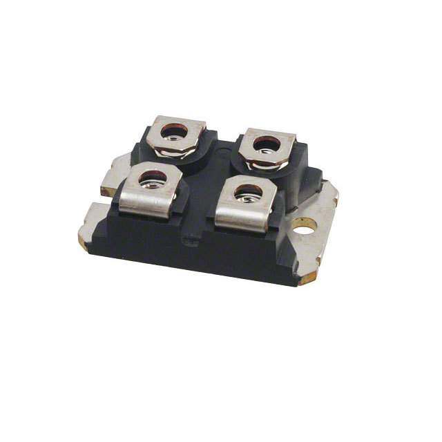
| 描述 | MOSFET N-CH 600V 84A SOT-227 |
| 产品分类 | FET - 模块 |
| FET功能 | 标准 |
| FET类型 | MOSFET N 通道,金属氧化物 |
| 品牌 | Microsemi Power Products Group |
| 数据手册 | http://www.microsemi.com/document-portal/doc_download/123471-apt80f60j-c-pdf |
| 产品图片 | |
| 产品型号 | APT80F60J |
| rohs | 无铅 / 符合限制有害物质指令(RoHS)规范要求 |
| 产品系列 | POWER MOS 8™ |
| 不同Id时的Vgs(th)(最大值) | 5V @ 2.5mA |
| 不同Vds时的输入电容(Ciss) | 23994pF @ 25V |
| 不同Vgs时的栅极电荷(Qg) | 598nC @ 10V |
| 不同 Id、Vgs时的 RdsOn(最大值) | 55 毫欧 @ 60A,10V |
| 供应商器件封装 | ISOTOP® |
| 功率-最大值 | 961W |
| 包装 | 管件 |
| 安装类型 | 底座安装 |
| 封装/外壳 | SOT-227-4,miniBLOC |
| 标准包装 | 10 |
| 漏源极电压(Vdss) | 600V |
| 电流-连续漏极(Id)(25°C时) | 84A |


- 商务部:美国ITC正式对集成电路等产品启动337调查
- 曝三星4nm工艺存在良率问题 高通将骁龙8 Gen1或转产台积电
- 太阳诱电将投资9.5亿元在常州建新厂生产MLCC 预计2023年完工
- 英特尔发布欧洲新工厂建设计划 深化IDM 2.0 战略
- 台积电先进制程称霸业界 有大客户加持明年业绩稳了
- 达到5530亿美元!SIA预计今年全球半导体销售额将创下新高
- 英特尔拟将自动驾驶子公司Mobileye上市 估值或超500亿美元
- 三星加码芯片和SET,合并消费电子和移动部门,撤换高东真等 CEO
- 三星电子宣布重大人事变动 还合并消费电子和移动部门
- 海关总署:前11个月进口集成电路产品价值2.52万亿元 增长14.8%



PDF Datasheet 数据手册内容提取
APT80F60J 6 00V, 84A, 0.055Ω Max, trr ≤ 370ns N-Channel FREDFET S S 7 Power MOS 8™ is a high speed, high voltage N-channel switch-mode power MOSFET. 22 G D - T This 'FREDFET' version has a drain-source (body) diode that has been optimized for O S high reliability in ZVS phase shifted bridge and other circuits through reduced trr, soft recovery, and high recovery dv/dt capability. Low gate charge, high gain, and a greatly reduced ratio of Crss/Ciss result in excellent noise immunity and low switching loss. "UL Recognized" ISOTOP ® file # E145592 The intrinsic gate resistance and capacitance of the poly-silicon gate structure help APT80F60J control di/dt during switching, resulting in low EMI and reliable paralleling, even when Single die FREDFET switching at very high frequency. FEATURES TYPICAL APPLICATIONS • Fast switching with low EMI • ZVS phase shifted and other full bridge • Low trr for high reliability • Half bridge • Ultra low Crss for improved noise immunity • PFC and other boost converter • Low gate charge • Buck converter • Avalanche energy rated • Single and two switch forward • RoHS compliant • Flyback Absolute Maximum Ratings Symbol Parameter Ratings Unit Continuous Drain Current @ T = 25°C 84 I C D Continuous Drain Current @ T = 100°C 52 A C I Pulsed Drain Current 1 447 DM VGS Gate-Source Voltage ±30 V EAS Single Pulse Avalanche Energy 2 3352 mJ IAR Avalanche Current, Repetitive or Non-Repetitive 60 A Thermal and Mechanical Characteristics Symbol Characteristic Min Typ Max Unit PD Total Power Dissipation @ TC = 25°C 961 W R Junction to Case Thermal Resistance 0.13 θJC °C/W R Case to Sink Thermal Resistance, Flat, Greased Surface 0.15 θCS T ,T Operating and Storage Junction Temperature Range -55 150 °C J STG VIsolation RMS Voltage (50-60hHz Sinusoidal Waveform from Terminals to Mounting Base for 1 Min.) 2500 V 1.03 oz 1 W 1 T Package Weight 20 29.2 g 4- C 10 in·lbf v Torque Terminals and Mounting Screws. Re 1.1 N·m 5 7 1 8 0- Microsemi Website - http://www.microsemi.com 5 0
Static Characteristics T = 25°C unless otherwise specifi ed APT80F60J J Symbol Parameter Test Conditions Min Typ Max Unit VBR(DSS) Drain-Source Breakdown Voltage VGS = 0V, ID = 250μA 600 V ∆VBR(DSS)/∆TJ Breakdown Voltage Temperature Coeffi cient Reference to 25°C, ID = 250μA 0.60 V/°C RDS(on) Drain-Source On Resistance 3 VGS = 10V, ID = 60A 0.042 0.055 Ω VGS(th) Gate-Source Threshold Voltage V = V , I = 2.5mA 2.5 4 5 V ∆V /∆T Threshold Voltage Temperature Coeffi cient GS DS D -10 mV/°C GS(th) J V = 600V T = 25°C 250 I Zero Gate Voltage Drain Current DS J μA DSS V = 0V T = 125°C 1000 GS J IGSS Gate-Source Leakage Current VGS = ±30V ±100 nA Dynamic Characteristics T = 25°C unless otherwise specifi ed J Symbol Parameter Test Conditions Min Typ Max Unit g Forward Transconductance V = 50V, I = 60A 117 S fs DS D C Input Capacitance V = 0V, V = 25V 23994 iss GS DS f = 1MHz C Reverse Transfer Capacitance 245 rss C Output Capacitance 2201 pF oss V = 0V, V = 0V to 400V C 4 Effective Output Capacitance, Charge Related GS DS 1170 o(cr) C 5 Effective Output Capacitance, Energy Related 606 o(er) Q Total Gate Charge V = 0 to 10V, I = 60A, 598 g GS D Q Gate-Source Charge VDS = 300V 128 nC gs Q Gate-Drain Charge 251 gd t Turn-On Delay Time Resistive Switching 134 d(on) V = 400V, I = 60A t Current Rise Time DD D 156 r R = 2.2Ω 6 , V = 15V ns t Turn-Off Delay Time G GG 408 d(off) t Current Fall Time 123 f Source-Drain Diode Characteristics Symbol Parameter Test Conditions Min Typ Max Unit Continuous Source Current IS (Body Diode) MshOoSwFinEgT t hseymbol 84 integral reverse p-n A Pulsed Source Current junction diode ISM (Body Diode) 1 (body diode) 447 VSD Diode Forward Voltage ISD = 60A, TJ = 25°C, VGS = 0V 1.2 V T = 25°C 370 t Reverse Recovery Time J ns rr T = 125°C 690 J I = 60A 3 T = 25°C 2.6 Q Reverse Recovery Charge SD J μC rr V = 100V T = 125°C 7.0 DD J di /dt = 100A/μs T = 25°C 14.5 I Reverse Recovery Current SD J A rrm T = 125°C 20 J I ≤ 60A, di/dt ≤1000A/μs, V = 400V, dv/dt Peak Recovery dv/dt SD DD 25 V/ns T = 125°C J 1 Repetitive Rating: Pulse width and case temperature limited by maximum junction temperature. 2 Starting at T = 25°C, L = 2.08mH, R = 25Ω, I = 60A. J G AS 1 3 Pulse test: Pulse Width < 380μs, duty cycle < 2%. 1 0 2 C 4- 54 CCo(cr) iiss ddeefifi nneedd aass aa fifi xxeedd ccaappaacciittaannccee wwiitthh tthhee ssaammee ssttoorreedd echnaerrggey aass CCOSS wwiitthh VVDS == 6677%% ooff VV(BR)DSS.. To calculate C for any value of v Vo(erl)ess than V use this equation: C = -3.14E-7/V ^2 + 7.31EO-S8S/ V + 2D.S0 9E-10. (BR)DSS o(er) Re DS (BR)DSS, o(er) DS DS 5 6 RG is external gate resistance, not including internal gate resistance or gate driver impedance. (MIC4452) 7 1 0-8 Microsemi reserves the right to change, without notice, the specifi cations and information contained herein. 5 0
APT80F60J 350 160 VGS = 10V TJ = 125°C VGS= 7,8 & 10V 300 140 T = -55°C NT (A) 250 J NT (A) 112000 6V E E R 200 R R R CU TJ = 25°C CU 80 N 150 N RAI RIA 60 D 100 D , D , D 40 I TJ = 150°C I 5V 50 20 T = 125°C 4.5V J 0 0 0 5 10 15 20 25 0 5 10 15 20 25 30 V , DRAIN-TO-SOURCE VOLTAGE (V) V , DRAIN-TO-SOURCE VOLTAGE (V) DS(ON) DS Figure 1, Output Characteristics Figure 2, Output Characteristics E 2.5 280 NC NORMALIZED TO VDS> ID(ON) x RDS(ON) MAX. STA VGS = 10V @ 42A 240 @25 0<μ0S.5E %C. DPUUTLYS EC YTCESLET SI 2.0 E ON RE 1.5 ENT (A) 200 TJ = -55°C C R 160 R R U U T = 25°C O C J O-S 1.0 AIN 120 T = 125°C T R J AIN- , DD 80 R 0.5 I D , N) 40 O DS( 0 0 R -55 -25 0 25 50 75 100 125 150 0 1 2 3 4 5 6 7 8 T, JUNCTION TEMPERATURE (°C) V , GATE-TO-SOURCE VOLTAGE (V) J GS Figure 3, R vs Junction Temperature Figure 4, Transfer Characteristics DS(ON) 120 20,000 10,000 C iss 100 E TJ = -55°C DUCTANC 80 TJ = 1T2J5 °=C 25°C NCE (pF) 1000 CON 60 CITA Coss S A N P A 40 A R C 100 g, Tfs 20 C, Crss 0 10 0 10 20 30 40 50 60 70 80 90 0 100 200 300 400 500 I , DRAIN CURRENT (A) V , DRAIN-TO-SOURCE VOLTAGE (V) D DS Figure 5, Gain vs Drain Current Figure 6, Capacitance vs Drain-to-Source Voltage 16 280 I = 42A GE (V) 14 D T (A) 240 OLTA 12 VDS = 100V RREN 200 V 10 U CE VDS = 250V N C 160 UR 8 RAI TJ = 25°C O D 120 GATE-TO-S 64 VDS = 400V REVERSE 80 TJ = 150°C 4-2011 V, GS 2 ISD, 40 v C 00 Q10,0 T OTAL2 0G0A TE C3H0A0R GE (4n0C0) 500 00 V , 0S.3O URCE0-.T6O -DRA0I.N9 VOLTA1.G2E (V)1.5 5 Re g SD 7 Figure 7, Gate Charge vs Gate-to-Source Voltage Figure 8, Reverse Drain Current vs Source-to-Drain Voltage 81 0- 5 0
APT80F60J 447 447 100 I 100 I DM DM A) A) T ( T ( N N RE 10 13μs RE 10 13μs R R 100μs U 100μs U N C Rds(on) 1ms N C Rds(on) 1ms AI 10ms AI 10ms , DRD 1 100DmCs line , DRD 1 TTJC = = 1 2550°°CC 100mDsC line I I Scaling for Different Case & Junction 0.11 TTVJC D= =S 1 ,72 5D5°°RCCAIN1-T0O -SOURCE V10O0L TAGE (V) 800 0.11 TeVmIDDp S=e, r IaDDtu(RTrCeAs I=:N 21-5T0°CO )-*S(TOJ U- TRCC)/E12 V510O0L TAGE (V)800 Figure 9, Forward Safe Operating Area Figure 10, Maximum Forward Safe Operating Area 0.25 W) D = 0.9 0.20 C/ CE (° 0.7 N A 0.15 D E P 0.5 M L I 0.10 Note: A RM 0.3 DM t1 E P , THθJC 0.05 0.1 Dtu1t =y FPauclstoe rtD 2Du =rat iot1n/t2 Z 0.05 SINGLE PULSE Peak TJ = PDM x ZθJC + TC 0 10-5 10-4 10-3 10-2 10-1 1.0 RECTANGULAR PULSE DURATION (seconds) Figure 11. Maximum Effective Transient Thermal Impedance Junction-to-Case vs Pulse Duration SOT-227 (ISOTOP®) Package Outline e3 100% Sn Plated 11.8 (.463) 31.5 (1.240) 12.2 (.480) 31.7 (1.248) 8.9 (.350) 7.8 (.307) W=4.1 (.161) 9.6 (.378) 8.2 (.322) W=4.3 (.169) Hex Nut M4 H=4.8 (.187) (4 places ) H=4.9 (.193) (4 places) r =(2 4 p.0la (c.1e5s)7 ) 4.0 (.157) 0.75 (.030) 12.6 (.496) 2255..24 ((01..909020)) 4.2 (.165) 0.85 (.033) 12.8 (.504) (2 places) 3.3 (.129) 1.95 (.077) 3.6 (.143) 2.14 (.084) 14.9 (.587) * Source Drain 15.1 (.594) 11 3300..13 ((11..118953)) *Einmteitrtnearl ltye.r Cmuirnraelns ta hrea nshdolinrtegd 20 38.0 (1.496) capability is equal for either 4- 38.2 (1.504) Source terminal. C * Source Gate v e R Dimensions in Millimeters and (Inches) 5 7 1 8 0- 5 0
 Datasheet下载


