ICGOO在线商城 > 分立半导体产品 > 晶体管 - FET,MOSFET - 单 > APT37F50B

 Datasheet下载
- 型号: APT37F50B
- 制造商: American Microsemiconductor, Inc.
- 库位|库存: xxxx|xxxx
- 要求:
| 数量阶梯 | 香港交货 | 国内含税 |
| +xxxx | $xxxx | ¥xxxx |
查看当月历史价格
查看今年历史价格
APT37F50B产品简介:
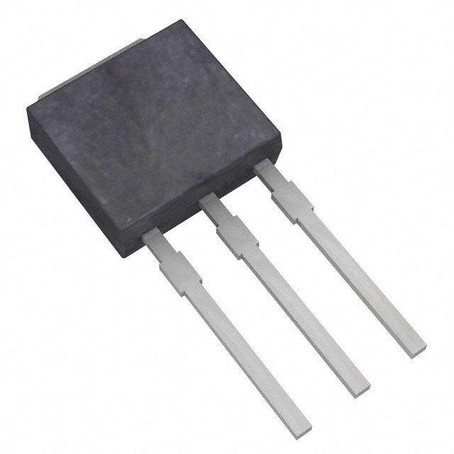
ICGOO电子元器件商城为您提供APT37F50B由American Microsemiconductor, Inc.设计生产,在icgoo商城现货销售,并且可以通过原厂、代理商等渠道进行代购。 APT37F50B价格参考。American Microsemiconductor, Inc.APT37F50B封装/规格:晶体管 - FET,MOSFET - 单, 通孔 N 沟道 500V 37A(Tc) 520W(Tc) TO-247 [B]。您可以下载APT37F50B参考资料、Datasheet数据手册功能说明书,资料中有APT37F50B 详细功能的应用电路图电压和使用方法及教程。
| 参数 | 数值 |
| 产品目录 | |
| 描述 | MOSFET N-CH 500V 37A TO-247 |
| 产品分类 | FET - 单 |
| FET功能 | 标准 |
| FET类型 | MOSFET N 通道,金属氧化物 |
| 品牌 | Microsemi Power Products Group |
| 数据手册 | http://www.microsemi.com/document-portal/doc_download/6980-apt37f50b-s-d-pdfhttp://www2.microsemi.com/document-portal/doc_download/14813-power-products-group-ppg-catalog |
| 产品图片 |
|
| 产品型号 | APT37F50B |
| rohs | 无铅 / 符合限制有害物质指令(RoHS)规范要求 |
| 产品系列 | - |
| 不同Id时的Vgs(th)(最大值) | 5V @ 1mA |
| 不同Vds时的输入电容(Ciss) | 5710pF @ 25V |
| 不同Vgs时的栅极电荷(Qg) | 145nC @ 10V |
| 不同 Id、Vgs时的 RdsOn(最大值) | 150 毫欧 @ 18A,10V |
| 产品目录绘图 |
|
| 产品目录页面 | |
| 供应商器件封装 | TO-247 [B] |
| 其它名称 | APT37F50BMI |
| 功率-最大值 | 520W |
| 包装 | 管件 |
| 安装类型 | 通孔 |
| 封装/外壳 | TO-247-3 |
| 标准包装 | 30 |
| 漏源极电压(Vdss) | 500V |
| 电流-连续漏极(Id)(25°C时) | 37A (Tc) |


- 商务部:美国ITC正式对集成电路等产品启动337调查
- 曝三星4nm工艺存在良率问题 高通将骁龙8 Gen1或转产台积电
- 太阳诱电将投资9.5亿元在常州建新厂生产MLCC 预计2023年完工
- 英特尔发布欧洲新工厂建设计划 深化IDM 2.0 战略
- 台积电先进制程称霸业界 有大客户加持明年业绩稳了
- 达到5530亿美元!SIA预计今年全球半导体销售额将创下新高
- 英特尔拟将自动驾驶子公司Mobileye上市 估值或超500亿美元
- 三星加码芯片和SET,合并消费电子和移动部门,撤换高东真等 CEO
- 三星电子宣布重大人事变动 还合并消费电子和移动部门
- 海关总署:前11个月进口集成电路产品价值2.52万亿元 增长14.8%


PDF Datasheet 数据手册内容提取
APT37F50B APT37F50S 500V, 37A, 0.15Ω Max, trr, ≤250ns N-Channel FREDFET Power MOS 8™ is a high speed, high voltage N-channel switch-mode power MOSFET. TO-247 This 'FREDFET' version has a drain-source (body) diode that has been optimized for D3PAK high reliability in ZVS phase shifted bridge and other circuits through reduced trr, soft recovery, and high recovery dv/dt capability. Low gate charge, high gain, and a greatly reduced ratio of Crss/Ciss result in excellent noise immunity and low switching loss. The APT37F50B APT37F50S intrinsic gate resistance and capacitance of the poly-silicon gate structure help control di/dt during switching, resulting in low EMI and reliable paralleling, even when switching Single die FREDFET at very high frequency. FEATURES TYPICAL APPLICATIONS • Fast switching with low EMI • ZVS phase shifted and other full bridge • Low trr for high reliability • Half bridge • Ultra low Crss for improved noise immunity • PFC and other boost converter • Low gate charge • Buck converter • Avalanche energy rated • Single and two switch forward • RoHS compliant • Flyback Absolute Maximum Ratings Symbol Parameter Ratings Unit Continuous Drain Current @ T = 25°C 37 I C D Continuous Drain Current @ TC = 100°C 24 A IDM Pulsed Drain Current 1 115 VGS Gate-Source Voltage ±30 V EAS Single Pulse Avalanche Energy 2 780 mJ IAR Avalanche Current, Repetitive or Non-Repetitive 18 A Thermal and Mechanical Characteristics Symbol Characteristic Min Typ Max Unit PD Total Power Dissipation @ TC = 25°C 520 W RθJC Junction to Case Thermal Resistance 0.24 °C/W RθCS Case to Sink Thermal Resistance, Flat, Greased Surface 0.11 T ,T Operating and Storage Junction Temperature Range -55 150 J STG °C T Soldering Temperature for 10 Seconds (1.6mm from case) 300 L 0.22 oz WT Package Weight 011 6.2 g 8-2 10 in·lbf v D Torque Mounting Torque (TO-247 Package), 6-32 or M3 screw e R 1.1 N·m 5 2 1 8 0- Microsemi Website - http://www.microsemi.com 05
Static Characteristics T = 25°C unless otherwise specifi ed APT37F50B_S J Symbol Parameter Test Conditions Min Typ Max Unit VBR(DSS) Drain-Source Breakdown Voltage VGS = 0V, ID = 250μA 500 V ∆VBR(DSS)/∆TJ Breakdown Voltage Temperature Coeff cient Reference to 25°C, ID = 250μA 0.60 V/°C RDS(on) Drain-Source On Resistance 3 VGS = 10V, ID = 18A 0.13 0.15 Ω VGS(th) Gate-Source Threshold Voltage V = V , I = 1mA 2.5 4 5 V ∆VGS(th)/∆TJ Threshold Voltage Temperature Coeff cient GS DS D -10 mV/°C I Zero Gate Voltage Drain Current VDS = 500V TJ = 25°C 250 μA DSS V = 0V T = 125°C 1000 GS J IGSS Gate-Source Leakage Current VGS = ±30V ±100 nA Dynamic Characteristics T = 25°C unless otherwise specifi ed J Symbol Parameter Test Conditions Min Typ Max Unit gfs Forward Transconductance VDS = 50V, ID = 18A 27 S Ciss Input Capacitance 5710 V = 0V, V = 25V Crss Reverse Transfer Capacitance GS f = 1MDHSz 75 Coss Output Capacitance 615 pF C 4 Effective Output Capacitance, Charge Related 355 o(cr) V = 0V, V = 0V to 333V GS DS Co(er) 5 Effective Output Capacitance, Energy Related 180 Q Total Gate Charge 145 g V = 0 to 10V, I = 18A, Qgs Gate-Source Charge GS D 32 nC V = 250V Qgd Gate-Drain Charge DS 65 td(on) Turn-On Delay Time R esistive Switching 25 t Current Rise Time V = 333V, I =(cid:3) 18A 29 r DD D ns t Turn-Off Delay Time R = 4.7Ω 6 , V = 15V 65 d(off) G GG t Current Fall Time 21 f Source-Drain Diode Characteristics Symbol Parameter Test Conditions Min Typ Max Unit Continuous Source Current IS (Body Diode) MshOoSwFinEgT t hseymbol 37 integral reverse p-n A Pulsed Source Current junction diode I 115 SM (Body Diode) 1 (body diode) VSD Diode Forward Voltage ISD = 18A, TJ = 25°C, VGS = 0V 1.2 V T = 25°C 250 trr Reverse Recovery Time J ns T = 125°C 450 J I = 18A 3 T = 25°C 0.88 Qrr Reverse Recovery Charge di S/Ddt = 100A/μs TJ = 125°C 2.18 μC SD J V = 100V T = 25°C 8.4 Irrm Reverse Recovery Current DD TJ = 125°C 11.8 A J I ≤ 18A, di/dt ≤1000A/μs, V = 333V, SD DD dv/dt Peak Recovery dv/dt 20 V/ns T = 125°C J 1 Repetitive Rating: Pulse width and case temperature limited by maximum junction temperature. 2 Starting at T = 25°C, L = 4.81mH, R = 25Ω, I = 18A. J G AS 3 Pulse test: Pulse Width < 380μs, duty cycle < 2%. 011 4 C is def ned as a f xed capacitance with the same stored charge as C with V = 67% of V . 2 o(cr) OSS DS (BR)DSS 8- 5 C is def ned as a f xed capacitance with the same stored energy as C with V = 67% of V . To calculate C for any value of v D VDo(Se rl)ess than V(BR)DSS, use this equation: Co(er) = -1.33E-7/VDS^2 + 3.06EO-S8S/ VDS + 8D.S8 3E-11. (BR)DSS o(er) e 5 R 6 RG is external gate resistance, not including internal gate resistance or gate driver impedance. (MIC4452) 2 1 Microsemi reserves the right to change, without notice, the specifi cations and information contained herein. 8 0- 5 0
APT37F50B_S 140 70 VGS = 10V T = -55°C TJ = 125°C VGS= 7 &,10V 120 J 60 6.5V T (A) 100 T (A) 50 N N E E RR 80 RR 40 6V U T = 25°C U C J C N 60 N 30 RAI RIA 5.5V I, DD 40 TJ = 150°C I, DD 20 5V 20 10 T = 125°C J 0 0 0 5 10 15 20 25 0 5 10 15 20 25 30 V , DRAIN-TO-SOURCE VOLTAGE (V) V , DRAIN-TO-SOURCE VOLTAGE (V) DS(ON) DS Figure 1, Output Characteristics Figure 2, Output Characteristics E 2.5 120 NC NORMALIZED TO VDS> ID(ON) x RDS(ON) MAX. SISTA 2.0 VGS = 10V @ 18A 100 @25 0<μ0S.5E %C. DPUUTLYS EC YTCESLET RE A) ON NT ( 80 E 1.5 E C R R R T = -55°C U U 60 J O C O-S 1.0 AIN TJ = 25°C T R 40 N- D DRAI 0.5 I, D 20 TJ = 125°C , N) O DS( 0 0 R -55 -25 0 25 50 75 100 125 150 0 1 2 3 4 5 6 7 8 T, JUNCTION TEMPERATURE (°C) V , GATE-TO-SOURCE VOLTAGE (V) J GS Figure 3, R vs Junction Temperature Figure 4, Transfer Characteristics DS(ON) 45 10,000 C iss 40 T = -55°C E 35 J NC TJ = 25°C F) UCTA 30 TJ = 125°C CE (p 1000 D 25 N N A O T NSC 20 PACI Coss RA 15 CA 100 g, Tfs 10 C, C 5 rss 0 10 0 5 10 15 20 25 30 35 0 100 200 300 400 500 I , DRAIN CURRENT (A) V , DRAIN-TO-SOURCE VOLTAGE (V) D DS Figure 5, Gain vs Drain Current Figure 6, Capacitance vs Drain-to-Source Voltage 16 120 ID = 18A GE (V) 14 T (A) 100 TA 12 EN OL VDS = 120V RR 80 CE V 10 VDS = 300V N CU R 8 AI 60 U R TO-SO 6 V = 480V RSE D 40 TJ = 25°C ATE- 4 DS EVE TJ = 150°C 011 V, GGS 2 IRSD, 20 v D 8-2 0 0 Re 0 Q5,0 T OTAL1 0G0A TE C1H5A0R GE (2n0C0) 250 0 V , 0S.O3 URCE0-.T6O -DRA0I.N9 VOLTA1.G2 E (V)1.5 5 g SD 2 Figure 7, Gate Charge vs Gate-to-Source Voltage Figure 8, Reverse Drain Current vs Source-to-Drain Voltage 81 0- 5 0
APT37F50B_S 200 200 100 100 I I DM DM T (A) T (A) Rds(on) N N E 10 E 10 R R 13μs R R CU 13μs CU 1001μmss AIN Rds(on) 100μs AIN 10ms , DRD 1 1m1s0ms , DRD 1 TTJC = = 1 2550°°CC 100DmCs line I I Scaling for Different Case & Junction T = 125°C 100ms Temperatures: 0.1 TJC = 75°C DC line 0.1 ID = ID(TC = 25°C)*(TJ - TC)/125 1 10 100 800 1 10 100 800 V , DRAIN-TO-SOURCE VOLTAGE (V) V , DRAIN-TO-SOURCE VOLTAGE (V) DS DS Figure 9, Forward Safe Operating Area Figure 10, Maximum Forward Safe Operating Area 0.25 D = 0.9 W) C/ 0.20 E (° 0.7 C N A 0.15 D E P 0.5 M Note: ERMAL I 0.10 0.3 PDM t1 t2 Z, THθJC 0.05 0.1 SINGLE PULSE PeakD Ttu1t J=y =FP auPclDstoeM rD D xu =Zraθt iJotC1n/ t+2 TC 0.05 0 10-5 10-4 10-3 10-2 10-1 1.0 RECTANGULAR PULSE DURATION (seconds) Figure 11. Maximum Effective Transient Thermal Impedance Junction-to-Case vs Pulse Duration 3 TO-247 (B) Package Outline D PAK Package Outline e1 SAC: Tin, Silver, Copper e3 100% Sn Plated 4.69 (.185) 4.98 (.196) 15.95 (.628) 13.41 (.528) 512...344199 (((...200059998))) 6.15 (.242) BSC 1156..4296 ((..661400)) 56..3280 ((..221424)) Drain(Heat Sink) 511...045877 (((...200056082))) 16.05(.632) 11..1054( (.0.04451)) 13.51(.532) Drain 2201..8406 ((..881495)) 3.50 (.138) R4e/1v8is/e9d5 1133..9799( (.5.55413)) R8/e2v9is/e9d7 1111..5611 ((..445537)) 3.81 (.150) 00..4566 ((..001282)) {3 Plcs} 1.27 (.050) D 8-2011 10..0401 6(.(0.1064)0) 1290..8312 ((..7880400.5))0 11(.1..047107 (().. 00M45a05x)). 1223DG....6181ar5372at ei((((....n001168125433)))) 2200....68017427 08((.. 11((..01005200))17)) 11..2322 ((..004582)) 5{122...490 P588l c(((s...200.178}582))) BS1C.40 (.055) Haanreeda P t34(L BlS..ea80aita16nsede k((d ..so 11(56fD L00re))aaidn)) v Source 5 Re 22..2519 ((..018072)) 5.45 (2.2-P1l5c)s B.SC GateDraSionurce 2 1 0-8 Dimensions in Millimeters (Inches) Dimensions in Millimeters (Inches) 5 0