ICGOO在线商城 > AP1703FWG-7
- 型号: AP1703FWG-7
- 制造商: Diodes Inc.
- 库位|库存: xxxx|xxxx
- 要求:
| 数量阶梯 | 香港交货 | 国内含税 |
| +xxxx | $xxxx | ¥xxxx |
查看当月历史价格
查看今年历史价格
AP1703FWG-7产品简介:
ICGOO电子元器件商城为您提供AP1703FWG-7由Diodes Inc.设计生产,在icgoo商城现货销售,并且可以通过原厂、代理商等渠道进行代购。 提供AP1703FWG-7价格参考¥询价-¥询价以及Diodes Inc.AP1703FWG-7封装/规格参数等产品信息。 你可以下载AP1703FWG-7参考资料、Datasheet数据手册功能说明书, 资料中有AP1703FWG-7详细功能的应用电路图电压和使用方法及教程。
| 参数 | 数值 |
| 产品目录 | 集成电路 (IC)集成电路 (IC) |
| 描述 | IC MPU RESET CIRC 2.63V SC59-3IC MPU RESET CIRC 2.63V SC59-3 |
| 产品分类 | |
| 品牌 | Diodes IncorporatedDiodes/Zetex |
| 数据手册 | |
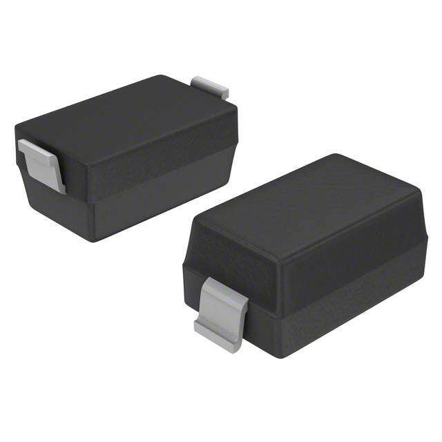
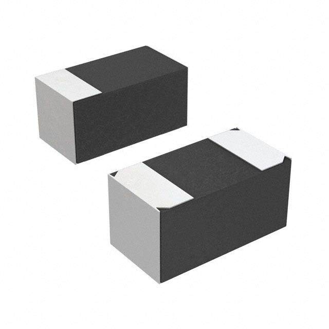
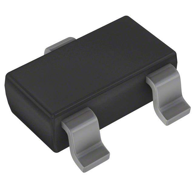
| 产品图片 |
|
| 产品型号 | AP1703FWG-7AP1703FWG-7 |
| PCN过时产品 | |
| rohs | 无铅 / 符合限制有害物质指令(RoHS)规范要求无铅 / 符合限制有害物质指令(RoHS)规范要求 |
| RoHS指令信息 | http://diodes.com/download/4349 |
| 产品系列 | -- |
| 供应商器件封装 | SC-59-3SC-59-3 |
| 其它名称 | AP1703FWGDICT |
| 包装 | 剪切带 (CT)带卷 (TR) |
| 受监控电压数 | 11 |
| 复位 | 低有效低有效 |
| 复位超时 | 最小为 100 ms最小为 100 ms |
| 安装类型 | 表面贴装表面贴装 |
| 封装/外壳 | TO-236-3,SC-59,SOT-23-3TO-236-3,SC-59,SOT-23-3 |
| 工作温度 | -40°C ~ 105°C-40°C ~ 105°C |
| 标准包装 | 13,000 |
| 电压-阈值 | 2.63V2.63V |
| 类型 | 简单复位/加电复位简单复位/加电复位 |
| 输出 | 推挽式,图腾柱推挽式,图腾柱 |



- 商务部:美国ITC正式对集成电路等产品启动337调查
- 曝三星4nm工艺存在良率问题 高通将骁龙8 Gen1或转产台积电
- 太阳诱电将投资9.5亿元在常州建新厂生产MLCC 预计2023年完工
- 英特尔发布欧洲新工厂建设计划 深化IDM 2.0 战略
- 台积电先进制程称霸业界 有大客户加持明年业绩稳了
- 达到5530亿美元!SIA预计今年全球半导体销售额将创下新高
- 英特尔拟将自动驾驶子公司Mobileye上市 估值或超500亿美元
- 三星加码芯片和SET,合并消费电子和移动部门,撤换高东真等 CEO
- 三星电子宣布重大人事变动 还合并消费电子和移动部门
- 海关总署:前11个月进口集成电路产品价值2.52万亿元 增长14.8%


PDF Datasheet 数据手册内容提取
NOT RECOMMENDED FOR NEW DESIGN, USE (APX809/810) AP1701/2/3/4 3-PIN MICROPROCESSOR RESET CIRCUITS Features General Description The AP1701/2/3/4 are used for microprocessor (µP) supervisory • Precision Monitoring of +2.5V, +3V, +3.3V, and +5V circuits to monitor the power supplies in µP and digital systems. Power-Supply Voltages They provide excellent circuit reliability and low cost by • Fully Specified Over Temperature eliminating external components and adjustments when used • Available in three Output Configurations with +5V, +3.3V, +3.0V powered circuits. • Push-PullRESET Low Output (AP1701/3) • Push-Pull RESET High Output (AP1702/4) These circuits perform a single function: they assert a reset signal whenever the V supply voltage declines below a preset • 200ms Min. Power-On Reset Pulse Width CC threshold, keeping it asserted for at least 240ms after V has • 20µA Supply Current (Typ.) CC risen above the reset threshold. Reset thresholds suitable for • Guaranteed Reset Valid to VCC = +1V operation with a variety of supply voltages are available. The • Power Supply Transient Immunity AP1701/2/3/4 have push pull outputs. The AP1701/3 have an • No External Components active low RESET output, while the AP1702/4 has an active • Green Packages: SC59-3L and SOT23 • Lead Free Finish / RoHS Compliant (Note 1) high RESET output. The reset comparator is designed to ignore fast transients on V , and the outputs are guaranteed to be in CC the correct logic state for V down to 1V. Low supply current CC makes the AP1701/2/3/4 ideal for use in portable equipment. The AP1701/2/3/4 is available in a 3-pin SC59 package. Applications • Computers • Controllers • Intelligent Instruments • Critical µP and µC Power Monitoring • Portable/Battery Powered Equipment • Automotive Ordering Information AP170 X X X X X Enable Voltage Package Lead Free Packing 1 : Active-Low A :4.63 W : SC59 L : Lead Free -7: Taping 2 : Active-High B :4.38 SA : SOT23 G : Green 3 : Active-Low C :4.00 4 : Active-High D :3.08 E :2.93 F : 2.63 G :2.25 Notes: 1. RoHS revision 13.2.2003. Glass and High Temperature Solder Exemptions Applied, see EU Directive Annex Notes 5 and 7. Package Packaging 7” Tape and Reel Device Code (Note 2) Quantity Part Number Suffix AP170XXW W SC59 3000/Tape & Reel -7 AP170XXSA SA SOT23 3000/Tape & Reel -7 Notes: 2. Pad layout as shown on Diodes Inc. suggested pad layout document AP02001, which can be found on our website at http://www.diodes.com/datasheets/ap02001.pdf. AP1701/2/3/4 Rev. 2 1 of 10 JANUARY 2007 www.diodes.com © Diodes Incorporated
NOT RECOMMENDED FOR NEW DESIGN, USE (APX809/810) AP1701/2/3/4 3-PIN MICROPROCESSOR RESET CIRCUITS Pin Assignments (Top View) (Top View) GND 1 1 RESET(RESET) AP1701 AP1703 AP1702 3 VCC AP1704 3 VCC 22 GND 22 RESET(RESET) SC59-3L SC59-3L 3 REF ANODE 1 2 CATHODE SOT23 Pin Descriptions Name Description GND Ground Reset Output Pin RESET L: for AP1701/3 (RESET) H: for AP1702/4 VCC Operating Voltage Input AP1701/2/3/4 Rev. 2 2 of 10 JANUARY 2007 www.diodes.com © Diodes Incorporated
NOT RECOMMENDED FOR NEW DESIGN, USE (APX809/810) AP1701/2/3/4 3-PIN MICROPROCESSOR RESET CIRCUITS Absolute Maximum Ratings Symbol Parameter Rating Unit V Terminal Voltage (with respect to GND) -0.3 to +6.0 V CC VRESET RESET, RESET (push-pull) -0.3 to (VCC + 0.3) V I Input Current, V 20 mA CC CC IO Output Current, RESET, RESET 20 mA Continuous Power Dissipation (T = +70°C), P A 320 mW D de-rate 4mW/°C above +70°C T Operating Junction Temperature Range -40 to +105 °C OP T Storage Temperature Range -65 to +150 °C ST Electrical Characteristics (T = 25ºC) A Symbol Parameter Conditions Min. Typ. Max. Unit V V Range T = 0oC to +70oC 1.0 5.5 V CC CC A I Supply Current V + 1.0V 20 30 μA CC TH AP1701/2/3/4A 4.54 4.63 4.72 AP1701/2/3/4B 4.29 4.38 4.47 AP1701/2/3/4C 3.92 4.00 4.08 Reset Threshold AP1701/2/3/4D 3.02 3.08 3.14 V T = 25ºC V A AP1701/2/3/4E 2.87 2.93 2.99 TH AP1701/2/3/4F 2.57 2.63 2.68 AP1701/2/3/4G 2.20 2.25 2.30 Reset Threshold ppm/ 30 Tempco oC T Set-up Time V = 0to (V – 100mV) 100 μs S CC TH Reset Active T T = 0oC to +70oC 100 240 600 ms DELAY Timeout Period A V = V min, I = 1.2mA, AP1701/3 0.3 CC TH SINK RESETOutput V V = V min, I = 3.2mA 0.4 V OL CC TH SINK Voltage Low V > 1.0V, I = 50uA 0.3 CC SINK V > V max, I = 500uA, AP1701/3 0.8V RESET Output CC TH SOURCE CC V V OH Voltage-High VCC > VTH max, ISOURCE = 800uA VCC –1.5 RESET Output V = V max, I = 1.2mA, AP1702/4 0.3 V CC TH SINK V OL Voltage-Low V = V max, I = 3.2mA 0.4 CC TH SINK RESET Output 1.8V < V < V min, I = 150uA, V CC TH SOURCE 0.8 V V OH Voltage-High AP1702/4 CC AP1701/2/3/4 Rev. 2 3 of 10 JANUARY 2007 www.diodes.com © Diodes Incorporated
NOT RECOMMENDED FOR NEW DESIGN, USE (APX809/810) AP1701/2/3/4 3-PIN MICROPROCESSOR RESET CIRCUITS Typical Application Circuit V CC Cin 0.1uF V V CC CC Microprocessor AP170X RESET RESET INPUT (RESET) GND GND Function Description A microprocessor’s (µP’s) reset input starts the µP in a below the reset threshold), RESET goes low. Any time V known state. The AP1701/2/3/4 assert reset to prevent CC code-execution errors during power-up, power-down, or goes below the reset threshold, the internal timer resets to zero, brownout conditions. They assert a reset signal whenever the VCC and RESET goes low. The internal timer starts after V supply voltage declines below a preset threshold, keeping it CC asserted for at least 240ms after VCC has risen above the reset returns above the reset threshold, and RESET remains low threshold. The AP1701/2/3/4 have a push-pull output stage. for the reset timeout period. Applications Information Negative-Going VCC Transients When VCC falls below 1V, the AP1701/3 RESET In addition to issuing a reset to the µP during power-up, output no longer sinks current—it becomes an open circuit. power-down, and brownout conditions, the AP1701/2/3/4 are Therefore, high-impedance CMOS logic inputs connected to relatively immune to short-duration negative-going V transients CC RESETcan drift to undetermined voltages. (glitches). This presents no problem in most applications since most µP and The AP1701/2/3/4 do not generate a reset pulse. The other circuitry is inoperative with VCC below 1V. However, in graph was generated using a negative going pulse applied to VCC, applications where RESETmust be valid down to 0V, adding a starting 0.5V above the actual reset threshold and ending below it by the magnitude indicated (reset comparator overdrive). The pull down resistor to RESET causes any stray leakage graph indicates the maximum pulse width a negative going V transient can have without causing a reset pulse. As the CC currents to flow to ground, holding RESET low. R1’s value is magnitude of the transient increases (goes farther below the not critical; 100k are large enough not to load RESET and reset threshold), the maximum allowable pulse width decreases. Typically, a VCC transient that goes 100mV below the reset small enough to pull RESET to ground. For the AP1702/4 if threshold and lasts 100µs or less will not cause a reset pulse. A RESET is required to remain valid for V < 1V. 0.1µF bypass capacitor mounted as close as possible to the V CC CC pin provides additional transient immunity. Benefits of Highly Accurate Reset Threshold Most µP supervisor ICs has reset threshold voltages Ensuring a Valid Reset Output between 5% and 10% below the value of nominal supply voltages. Down to V = 0 CC This ensures a reset will not occur within 5% of the nominal RESET is guaranteed to be a logic low for V > 1V. supply, but will occur when the supply is 10% below nominal. CC Once V exceeds the reset threshold, an internal timer keeps When using ICs rated at only the nominal supply ±5%, this leaves CC a zone of uncertainty where the supply is between 5% and 10% RESET low for the reset timeout period; after this interval, low, and where the reset may or may not be asserted. RESET goes high. If a brownout condition occurs (V dips CC RESET AP1701/2/3/4 Rev. 2 4 of 10 JANUARY 2007 www.diodes.com © Diodes Incorporated
NOT RECOMMENDED FOR NEW DESIGN, USE (APX809/810) AP1701/2/3/4 3-PIN MICROPROCESSOR RESET CIRCUITS Block Diagram Driver Delay Circuit RESET / RESET VREF Performance Characteristics Threshold 24 2.928 20 2.926 16 Iq 12 2.924 8 2.922 4 2.92 0 -50 -40 -30 -20 -10 0 10 20 30 40 50 60 70 80 90 100 110 120 -40 -30 -20 -10 0 10 20 30 40 50 60 70 80 90 Temp ( C ) Temp Iq vs. Temp Threshold vs. Temp AP1701/2/3/4 Rev. 2 5 of 10 JANUARY 2007 www.diodes.com © Diodes Incorporated
NOT RECOMMENDED FOR NEW DESIGN, USE (APX809/810) AP1701/2/3/4 3-PIN MICROPROCESSOR RESET CIRCUITS Timing Diagram V TH V CC T T DELAY DELAY Active Low T S Active High T T DELAY DELAY Giltch Immunity 3500 nt 3000 3000 nsie s) 2500 Tra n(u 2000 mum uratio 1500 axi D 1000 900 M 500 270 0 140 90 70 58 50 50 48 48 0 100 200 300 400 500 600 700 800 900 1000 1100 RESET COMPARATOR OVERDRIVE(mV) AP1701/2/3/4 Rev. 2 6 of 10 JANUARY 2007 www.diodes.com © Diodes Incorporated
NOT RECOMMENDED FOR NEW DESIGN, USE (APX809/810) AP1701/2/3/4 3-PIN MICROPROCESSOR RESET CIRCUITS Marking Information (1) SC59-3L (Top View) 3 XX : Identification code Y : Year 0-9 XX Y M X M : Month A~L L : Lead Free Package G : Green Package 1 2 (2) SOT23 (Top View) Y : Year M: Month (A~L) XXY M X Marking Code X : L : Lead Free G :Green AP1701/2/3/4 Rev. 2 7 of 10 JANUARY 2007 www.diodes.com © Diodes Incorporated
NOT RECOMMENDED FOR NEW DESIGN, USE (APX809/810) AP1701/2/3/4 3-PIN MICROPROCESSOR RESET CIRCUITS Marking Information (Continued) Device Package (Note 3) Identification Code AP1701ASA SOT23 AP1701BSA SOT23 AP1701CSA SOT23 AP1701DSA SOT23 AP1701ESA SOT23 AP1701FSA SOT23 AP1701GSA SOT23 AP1702ASA SOT23 AP1702BSA SOT23 AP1702CSA SOT23 AP1702DSA SOT23 AP1702ESA SOT23 AP1702FSA SOT23 AP1702GSA SOT23 AP1703ASA SOT23 AP1703BSA SOT23 AP1703CSA SOT23 AP1703DSA SOT23 AP1703ESA SOT23 AP1703FSA SOT23 AP1703GSA SOT23 AP1704ASA SOT23 AP1704BSA SOT23 AP1704CSA SOT23 AP1704DSA SOT23 AP1704ESA SOT23 AP1704FSA SOT23 AP1704GSA SOT23 AP1701AW SC59 EA AP1701BW SC59 EB AP1701CW SC59 EC AP1701DW SC59 ED AP1701EW SC59 EE AP1701FW SC59 EF AP1701GW SC59 W1 AP1702AW SC59 E0 AP1702BW SC59 E2 AP1702CW SC59 E3 AP1702DW SC59 E4 AP1702EW SC59 E5 AP1702FW SC59 E6 AP1702GW SC59 W2 AP1703AW SC59 EG AP1703BW SC59 EH AP1703CW SC59 EI AP1703DW SC59 EJ AP1703EW SC59 EK AP1703FW SC59 EL AP1703GW SC59 W3 AP1704AW SC59 E7 AP1704BW SC59 E8 AP1704CW SC59 E9 AP1704DW SC59 EM AP1704EW SC59 EN AP1704FW SC59 EP AP1704GW SC59 W4 Notes: 3. For Packaging Details, go to our website at http://www.diodes.com/datasheets/ap02007.pdf. AP1701/2/3/4 Rev. 2 8 of 10 JANUARY 2007 www.diodes.com © Diodes Incorporated
NOT RECOMMENDED FOR NEW DESIGN, USE (APX809/810) AP1701/2/3/4 3-PIN MICROPROCESSOR RESET CIRCUITS Package Information (All Dimensions in mm) (1) Package Type: SC59-3L 0.35/0.50 TOP VIEW 50/702.70/ 1.1.3.00 1.90 2.90/3.10 1.00/ 1.30 0.10/0.20 0.013/0.10 0.95 0.35/0.55 0°/8° (2) Package Type: SOT23 0.37/0.51 0 0 4 5 1. 2. 0/ 0/ 2 3 1. 2. TOP VIEW 0.89/ 1.03 0.45/0.60 1.80/2.00 2.80/3.00 3/ 00 0.91.1 0.085/0.180 0.013/ 0.10 0.45/0.61 0º/8º AP1701/2/3/4 Rev. 2 9 of 10 JANUARY 2007 www.diodes.com © Diodes Incorporated
NOT RECOMMENDED FOR NEW DESIGN, USE (APX809/810) AP1701/2/3/4 3-PIN MICROPROCESSOR RESET CIRCUITS IMPORTANT NOTICE Diodes Incorporated and its subsidiaries reserve the right to make modifications, enhancements, improvements, corrections or other changes without further notice to any product herein. Diodes Incorporated does not assume any liability arising out of the application or use of any product described herein; neither does it convey any license under its patent rights, nor the rights of others. The user of products in such applications shall assume all risks of such use and will agree to hold Diodes Incorporated and all the companies whose products are represented on our website, harmless against all damages. LIFE SUPPORT Diodes Incorporated products are not authorized for use as critical components in life support devices or systems without the expressed written approval of the President of Diodes Incorporated. AP1701/2/3/4 Rev. 2 10 of 10 JANUARY 2007 www.diodes.com © Diodes Incorporated
 Datasheet下载
