ICGOO在线商城 > 继电器 > 功率继电器,高于 2 A > ALFG2PF18
- 型号: ALFG2PF18
- 制造商: Panasonic Corporation
- 库位|库存: xxxx|xxxx
- 要求:
| 数量阶梯 | 香港交货 | 国内含税 |
| +xxxx | $xxxx | ¥xxxx |
查看当月历史价格
查看今年历史价格
ALFG2PF18产品简介:
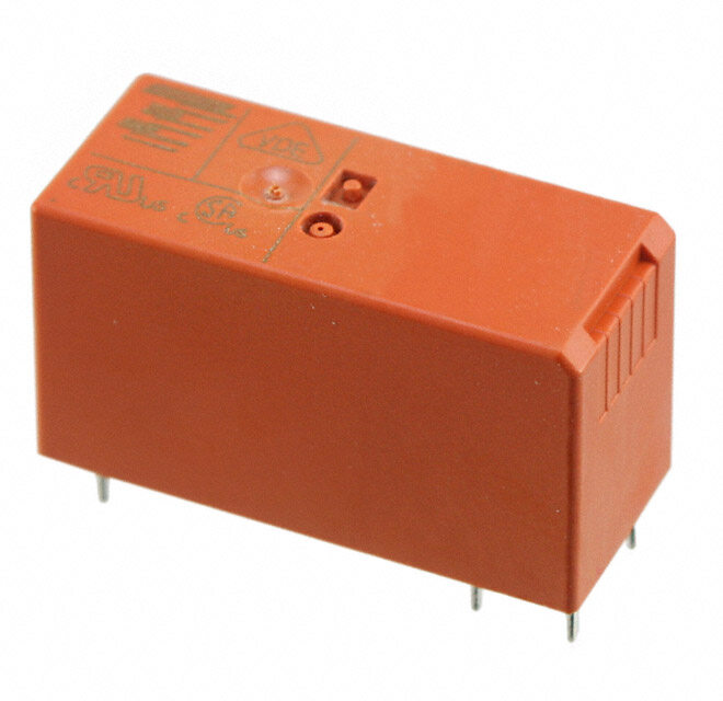
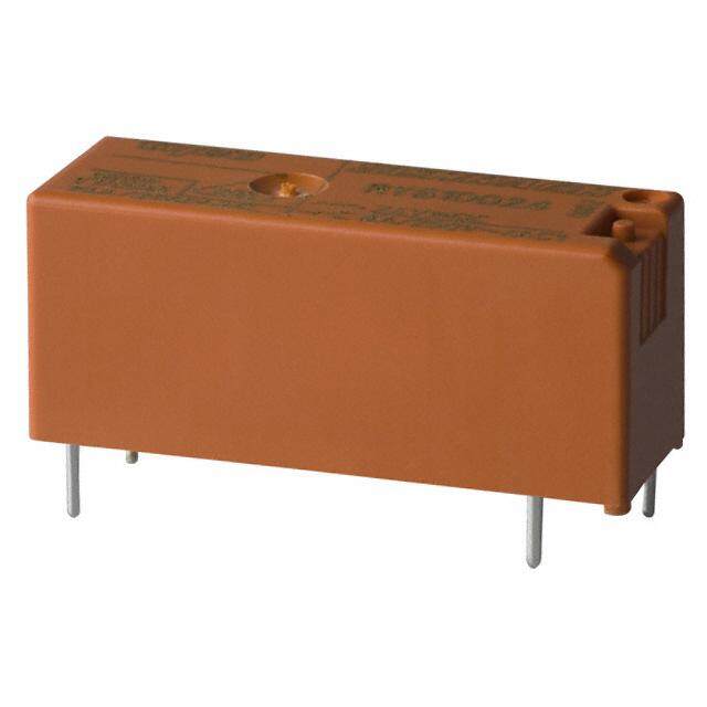
ICGOO电子元器件商城为您提供ALFG2PF18由Panasonic Corporation设计生产,在icgoo商城现货销售,并且可以通过原厂、代理商等渠道进行代购。 ALFG2PF18价格参考。Panasonic CorporationALFG2PF18封装/规格:功率继电器,高于 2 A, 通用 继电器 SPST-NO(1 Form A) 18VDC 线圈 通孔。您可以下载ALFG2PF18参考资料、Datasheet数据手册功能说明书,资料中有ALFG2PF18 详细功能的应用电路图电压和使用方法及教程。
Panasonic Electric Works 生产的 ALFG2PF18 功率继电器是一款额定电流高于 2A 的设备,适用于多种工业和商业应用场景。以下是该型号继电器的一些典型应用:

 1. 工业自动化控制系统
ALFG2PF18 继电器常用于工厂自动化系统中,作为控制电路的一部分,用于开关电动机、电磁阀、加热器等大功率负载。它能够承受较高的电流,确保在频繁启动和停止的情况下保持稳定工作。

 2. 楼宇自动化
在智能建筑中,该继电器可用于控制照明系统、空调系统、电梯等设备。通过与传感器和其他控制设备配合,ALFG2PF18 可以实现对电力负载的精确控制,提高能源利用效率。

 3. 家电设备
一些大型家用电器如洗衣机、烘干机、冰箱等也可能会使用到这种继电器。它能够处理较大的电流波动,保证电器在高负荷下的正常运行。

 4. 电动汽车充电站
随着电动汽车的普及,充电站的建设需求增加。ALFG2PF18 继电器可以用于充电站的电源管理模块,确保充电过程中的电流安全传输,并防止过载或短路等问题。

 5. 医疗设备
在某些需要高可靠性和精确控制的医疗设备中,如X光机、CT扫描仪等,ALFG2PF18 继电器可以用来控制高压发生器或其他关键组件,确保设备的安全性和稳定性。

 6. 通信基站
通信基站中的电源管理系统通常需要可靠的继电器来切换不同的电源路径。ALFG2PF18 继电器可以满足这一需求,提供稳定的电流控制,确保基站的不间断运行。

 7. 太阳能逆变器
在太阳能发电系统中,逆变器是将直流电转换为交流电的关键部件。ALFG2PF18 继电器可以用于逆变器的内部电路,帮助实现高效的电力转换和分配。

总之,ALFG2PF18 功率继电器凭借其高电流承载能力和可靠性,广泛应用于各种需要精确电流控制的场合,特别是在那些对安全性要求较高的领域。
| 参数 | 数值 |
| 产品目录 | |
| 描述 | RELAY GEN PURPOSE SPST 31A 18V通用继电器 1 Form A Hh Cap 31A 18volts |
| 产品分类 | |
| 品牌 | Panasonic Industrial Devices |
| 产品手册 | |
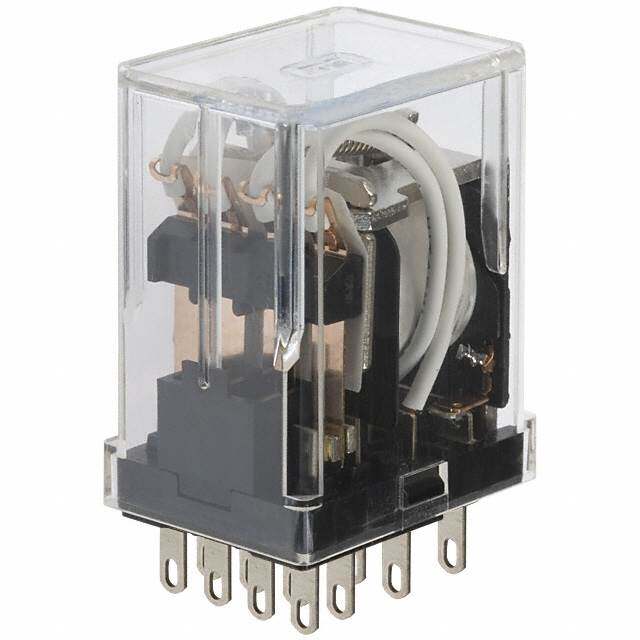
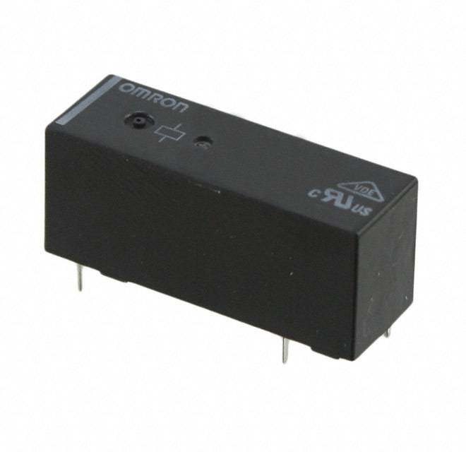
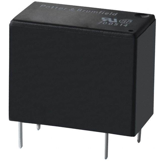
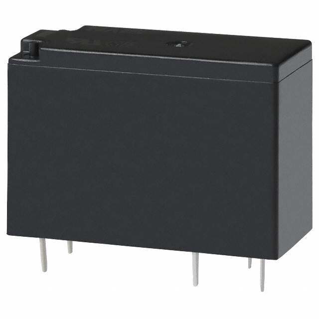
| 产品图片 |
|
| rohs | RoHS 合规性豁免无铅 / 符合限制有害物质指令(RoHS)规范要求 |
| 产品系列 | 通用继电器,Panasonic Industrial Devices ALFG2PF18ALFG |
| mouser_ship_limit | 该产品可能需要其他文件才能进口到中国。 |
| 数据手册 | |
| 产品型号 | ALFG2PF18 |
| 产品目录绘图 |
|
| 产品目录页面 | |
| 产品种类 | 通用继电器 |
| 关闭电压(最小值) | 1.8 VDC |
| 其它名称 | 255-2639 |
| 其它有关文件 | |
| 功耗 | 1400 mW |
| 包装 | 散装 |
| 商标 | Panasonic Industrial Devices |
| 安装类型 | 通孔 |
| 安装风格 | Through Hole |
| 导通电压(最大值) | 12.6 VDC |
| 封装 | Tube |
| 工作时间 | 20ms |
| 工作温度 | -40°C ~ 60°C |
| 工厂包装数量 | 50 |
| 开关电压 | 250VAC - 最小值 |
| 标准包装 | 50 |
| 特性 | 绝缘 - F 类 |
| 端子类型 | PC 引脚 |
| 端接类型 | Quick Connect Terminal |
| 线圈功率 | 1.4 W |
| 线圈电压 | 18 V |
| 线圈电流 | 78mA |
| 线圈电阻 | 230 欧姆 |
| 线圈端接 | Solder Pin |
| 线圈类型 | 无锁存 |
| 继电器类型 | 通用 |
| 触头外形 | SPST-NO(1 A 型) |
| 触头材料 | 银锡氧化物(AgSnO) |
| 触点形式 | SPST (1 Form A) |
| 触点材料 | Silver Tin Oxide |
| 触点端接 | Solder Terminal |
| 释放时间 | 10ms |
| 额定接触(电流) | 31A |




- 商务部:美国ITC正式对集成电路等产品启动337调查
- 曝三星4nm工艺存在良率问题 高通将骁龙8 Gen1或转产台积电
- 太阳诱电将投资9.5亿元在常州建新厂生产MLCC 预计2023年完工
- 英特尔发布欧洲新工厂建设计划 深化IDM 2.0 战略
- 台积电先进制程称霸业界 有大客户加持明年业绩稳了
- 达到5530亿美元!SIA预计今年全球半导体销售额将创下新高
- 英特尔拟将自动驾驶子公司Mobileye上市 估值或超500亿美元
- 三星加码芯片和SET,合并消费电子和移动部门,撤换高东真等 CEO
- 三星电子宣布重大人事变动 还合并消费电子和移动部门
- 海关总署:前11个月进口集成电路产品价值2.52万亿元 增长14.8%
.jpg)
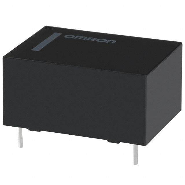

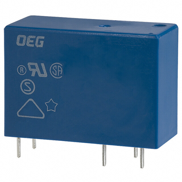
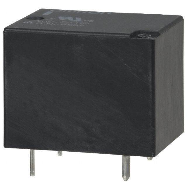
PDF Datasheet 数据手册内容提取
Load for solar inverter, Compact size, LF-G RELAYS (ALFG) 1 Form A 22A/33A power relays 2. Contact gap: 1.5 mm .059 inch and *Coil holding voltage is the coil voltage 1.8 mm*** .071 inch after 100 ms from the applied nominal Compliant with European photovoltaic coil voltage. standard (IEC62109* and VDE0126**). *When the ambient temperature during *Safety standard of PV power inverter use is 85°C 185°F, make the coil holding **German safety standard of PV power inverter voltage between 45% and 80%V of the ***Due to addition of altitude stipulation (2,000 m nominal coil voltage. 6,561.68 ft or more) to IEC62109. 5. Conforms to various safety EN61810-1 certified: 2.5 kV surge standards breakdown voltage (between contacts) UL/C-UL and VDE approved 3. Long insulation distance RoHS compliant Creepage distance between contact and coil terminal: Min. 9.5 mm .354 inch TYPICAL APPLICATIONS Protective construction: Flux-resistant Clearance distance between contact and type 1. Photovoltaic power generation coil terminal: Min. 6.5 mm .256 inch systems (Solar inverter) Surge breakdown voltage: 6 kV FEATURES 2. Uninterruptible Power Supplies 4. Coil holding voltage contributes to (UPS) 1. High capacity saving energy of equipment 3. Home appliances High capacity control possible at 22A/ The coil holding voltage can be reduced 4. Office equipment 33A (High capacity type) 250V AC rating up to 35%V of the nominal coil voltage in compact size (L: 15.7 × W: 30.1 × (Ambient temperature: 20°C 68°F). H: 23.3 mm L: .618 × W: 1.185 × H: .917 Power consumption at the lowest coil inch) holding voltage: 170 mW equivalent ORDERING INFORMATION ALFG P F LF-G relay Contact arrangement 1: 1 Form A Standard type 2: 1 Form A High capacity type Terminal shape P: PCB type Coil insulation class F: UL Class F Nominal coil voltage (DC) 09: 9V, 12: 12V, 18: 18V, 24: 24V Contact gap Nil: 1.5 mm .059 inch 1: 1.8 mm .071 inch Note: Certified by UL/C-UL and VDE TYPES Part No. Contact Nominal coil Contact Gap 1.5 mm .059 inch type Contact Gap 1.8 mm .071 inch type arrangement voltage Standard type High capacity type Standard type High capacity type 9V DC ALFG1PF09 ALFG2PF09 ALFG1PF091 ALFG2PF091 12V DC ALFG1PF12 ALFG2PF12 ALFG1PF121 ALFG2PF121 1 Form A 18V DC ALFG1PF18 ALFG2PF18 ALFG1PF181 ALFG2PF181 24V DC ALFG1PF24 ALFG2PF24 ALFG1PF241 ALFG2PF241 Standard packing: Carton: 50 pcs.; Case: 200 pcs. –1– ASCTB196E 201606-T
LF-G (ALFG) RATING 1. Coil data Pick-up voltage Drop-out voltage Nominal operating Novmoilntaagl ecoil (at 2(0In°iCtia 6l)8°F) (at 2(0In°iCtia 6l)8°F) [±10%] c(autr r2e0n°tC 68°F) [±10C%o]i l (raets 2is0t°aCn c6e8 °F) Nominpaol wopeerrating Ma(xa. ta 2p0p°liCe d6 8vo°Flt)age 9V DC 155mA 58Ω 12V DC 70%V or less of 10%V or more of 117mA 103Ω 120%V of 1,400mW 18V DC nominal voltage nominal voltage 78mA 230Ω nominal voltage 24V DC 59mA 410Ω 2. Specifications Specifications Standard type High capacity type Characteristics Item Contact Gap 1.5 mm .059 inch type Contact Gap 1.5 mm .059 inch type Contact Gap 1.8 mm .071 inch type Contact Gap 1.8 mm .071 inch type Arrangement 1 Form A Contact Contact resistance (Initial) Max. 100 mΩ (By voltage drop 6 V DC 1A) Contact material AgSnO2 type Nominal switching capacity 22A 250V AC 31A 250V AC 33A 250V AC Max. switching power 5,500VA 7,750VA 8,250VA Max. switching voltage 250V AC Rating Max. switching current 22A (AC) 31A (AC) 33A (AC) Nominal operating power 1,400mW Min. switching capacity 100mA 5V DC (Reference value)*1 Insulation resistance (Initial) Min. 1,000MΩ (at 500V DC) Measurement at same location as “Breakdown voltage” section. Between open 2,500 Vrms for 1 min. (Detection current: 10 mA) Breakdown contacts voltage (Initial) Between contact 4,000 Vrms for 1 min. (Detection current: 10 mA) and coil Surge breakdown voltage*2 Electrical 6,000 V (Between contact and coil) (Initial) characteristics 35 to 120%V (contact carrying 35 to 120%V (contact carrying 35 to 120%V (contact carrying current: 22A, at 20°C 68°F) current: 31A, at 20°C 68°F) current: 33A, at 20°C 68°F) Coil holding voltage*3 45 to 80%V (contact carrying 45 to 80%V (contact carrying 45 to 80%V (contact carrying current: 22A, at 85°C 185°F) current: 31A, at 85°C 185°F) current: 33A, at 85°C 185°F) Operate time (at 20°C 68°F) (Initial) Max. 20 ms (at nominal coil voltage excluding contact bounce time.) Release time (at 20°C 68°F) (Initial) Max. 10 ms (at nominal coil voltage excluding contact bounce time, without diode) Shock Functional Min. 100 m/s2 (Half-wave pulse of sine wave: 11 ms; detection time: 10μs.) Mechanical resistance Destructive Min. 1,000 m/s2 (Half-wave pulse of sine wave: 6 ms.) characteristics Vibration Functional 10 to 55 Hz at double amplitude of 1.5 mm (Detection time: 10μs.) resistance Destructive 10 to 55 Hz at double amplitude of 1.5 mm Contact Gap 1.5 mm .059 inch type: Min. 106 (at 180 times/min.) Mechanical Contact Gap 1.8 mm .071 inch type: Min. 5×10⁵ (at 180 times/min.) 22A 250V AC, Min. 3×10⁴ Resistive load — — (at 20 times/min.) Expected life Destructive: 22A 250V AC Destructive: 31A 250V AC Destructive: 33A 250V AC Electrical (cosφ = 0.8), (cosφ = 0.8), (cosφ = 0.8), Min. 3×10⁴ (on:off = 0.1s:10s) Min. 3×10⁴ (on:off = 0.1s:10s) Min. 3×10⁴ (on:off = 0.1s:10s) Inductive load Over load: 35A 250V AC Over load: 47A 250V AC Over load: 50A 250V AC (cosφ = 0.8), (cosφ = 0.8), (cosφ = 0.8), Min. 50 (on:off = 0.1s:10s) Min. 50 (on:off = 0.1s:10s) Min. 50 (on:off = 0.1s:10s) Ambient temperature: –40°C to +60°C –40°F to +140°F (When nominal coil voltage applied) –40°C to +85°C –40°F to +185°F (Coil holding voltage is when 45 to 80%V Conditions for operation, transport Conditions of nominal coil voltage is applied.) and storage*4 Humidity: 5 to 85% R.H. (Not freezing and condensing at low temperature) Air pressure: 86 to 106 kPa Unit weight Approx. 23 g .81 oz Notes:*1.This value can change due to the switching frequency, environmental conditions, and desired reliability level, therefore it is recommended to check this with the actual load. *2.Wave is standard shock voltage of ±1.2×50μs according to JEC-212-1981 *3.Coil holding voltage is the coil voltage after 100 ms from the applied nominal coil voltage. *4.The upper limit of the ambient temperature is the maximum temperature that can satisfy the coil temperature rise value. Refer to Usage, transport and storage conditions in NOTES. –2– ASCTB196E 201606-T
LF-G (ALFG) REFERENCE DATA 1. Standard type (Contact Gap 1.5 mm .059 inch type) (Contact Gap 1.8 mm .071 inch type) 1. Coil temperature rise 2. Ambient temperature characteristics and coil Sample: ALFG1PF09, ALFG1PF091, 6 pcs. applied voltage Point measured: coil inside Ambient temperature: 20°C 68°F, 60°C 140°F Contact carrying current: 22A 100 20°C68°F22A *Inside the coil temperature 155°C311°F(UL Class F) 180 C 60°C140°F22A %V Aaglloawinasbt l%e acmoibl vieonltta tgeemsperatures °mperature rise, 8600 6200°°CC16480°F°F00AA applied voltage, 114000 Ccuornretanct:t 2c2aArryin(sgme ta axs. in1s5i5d°eC th3e1 1c°oFil) temperature Te oil C 40 60 Pick-up voltage Coil & contact no carrying current 20 0 60 80 100 120 140 0 10 20 30 40 50 60 70 80 90 32 50 68 86 104122140158176194 Coil applied voltage, %V Ambient temperature, °C°F 3. Electrical life test (22A 250V AC Resistive load) Change of pick-up and drop-out voltage Change of contact resistance Sample: ALFG1PF09, ALFG1PF091, 6 pcs. Operation frequency: ON:OFF = 1.5s:1.5s 10 100 AC2m5ir0cbVui AeiCnt:t temperature: 85°C 198V5 D°FC Contact welding detection and Mis-contacting detection circuit Pick-up and drop-out voltage, V 9876543210 DPriocpk--uopu tv vooltlataggee MMxMMxaiainnxx.... ΩContact resistance, m 9876543210000000000 MMxainx.. 0 3 0 3 No. of operations, ×104 No. of operations, ×104 4. Electrical life test (22A 250V AC cosφ = 0.8 Inductive load) Change of pick-up and drop-out voltage Change of contact resistance Sample: ALFG1PF09, ALFG1PF091, 6 pcs. Operation frequency: ON:OFF = 0.1s:10s 10 100 AC2m5ir0cbVui AeiCnt:t temperature: 85°C 198V5 D°FC Contact welding detection and Mis-contacting detection circuit Pick-up and drop-out voltage, V 9876543210 DPriocpk--uopu tv vooltlataggee MMxMMxaiainnxx.... ΩContact resistance, m 9876543210000000000 MMxainx.. 0 3 0 3 No. of operations, ×104 No. of operations, ×104 –3– ASCTB196E 201606-T
LF-G (ALFG) 2. High capacity type (Contact Gap 1.5 mm .059 inch type) 1. Coil temperature rise 2. Ambient temperature characteristics and coil Sample: ALFG2PF09, 6 pcs. applied voltage Point measured: coil inside Ambient temperature: 20°C 68°F, 60°C 140°F Contact carrying current: 31A 100 20°C68°F31A *Inside the coil temperature 180 155°C311°F(UL Class F) 60°C140°F31A V Allowable ambient temperatures C % against % coil voltages °e rise, 80 6200°°CC16480°F°F00AA oltage, 140 (smeta axs. in1s5i5d°eC th3e1 1c°oFil) temperature mperatur 60 applied v100 Ccuornretanct:t 3c1aArrying Te oil C 40 60 Pick-up voltage Coil & contact no carrying current 20 0 60 80 100 120 140 0 10 20 30 40 50 60 70 80 90 32 50 68 86 104122140158176194 Coil applied voltage, %V Ambient temperature, °C°F 3. Electrical life test Change of pick-up and drop-out voltage Change of contact resistance (31A 250V AC cosφ = 0.8 Inductive load) 10 100 Sample: ALFG2PF09, 6 pcs. OAC2mp5ir0ecbVrui aAeiCtnti:ot nte fmrepqeureantucrye: : O8N5°:OC F1F98V 5= D° FC0.1s:10s Contact welding detection and Mis-contacting detection circuit Pick-up and drop-out voltage, V 98765432100 DNProioc. pko--fuo opup tv evoorlatlattaigogenes, ×104 3MMxMMxaiainnxx.... ΩContact resistance, m 98765432100000000000 No. of operations, ×104 3MMxainx.. 3. High capacity type (Contact Gap 1.8 mm .071 inch type) 1. Coil temperature rise 2. Ambient temperature characteristics and coil Sample: ALFG2PF091, 6 pcs. applied voltage Point measured: coil inside Ambient temperature: 20°C 68°F, 60°C 140°F Contact carrying current: 33A 120 248 *Inside the coil temperature °°Temperature rise, CF1211086174000260 26620000°°°°CCCC1166448800°°FF°°FF30303A3AAA Coil applied voltage, %V111840000 Ccuornretanct:t 3c3aArryinAa(sgmegl ltoaa awixns.a s1 ibnt15 ls%5e5i5d ° a°cCeCmo ti3hbl3 1evi1e1o 1nc°l°totFa Fitgle)( UtemesLmp eCprelaartsaustru eFrse) 40 60 Pick-up voltage 104 Coil & contact no carrying current 20 68 60 80 100 120 140 0 10 20 30 40 50 60 70 80 90 32 50 68 86 104122140158176194 Coil applied voltage, %V Ambient temperature, °C°F 3. Electrical life test Change of pick-up and drop-out voltage Change of contact resistance (33A 250V AC cosφ = 0.8 Inductive load) 10 100 Sample: ALFG2PF091, 6 pcs. OAC2mp5ir0ecbVrui aAeiCtnti:ot nte fmrepqeureantucrye: : O8N5°:OC F1F98V 5= D° FC0.1s:10s Contact welding detection and Mis-contacting detection circuit Pick-up and drop-out voltage, V 98765432100 DNProioc.p ko--fuo opup tv evoorlatlattaigogenes, ×104 3MMxMMxaiainnxx.... ΩContact resistance, m 98765432100000000000 No. of operations, ×104 3MMxainx.. –4– ASCTB196E 201606-T
LF-G (ALFG) DIMENSIONS (mm inch) The CAD data of the products with a CAD Data mark can be downloaded from: http://industrial.panasonic.com/ac/e/ CAD Data External dimensions PC board pattern (Bottom view) 27.6±0.1 1.087±.004 13.8±0.1 .00.250 2.931.37 .0729.0 d diaia.. .543±.004 2..0 0d7i9a .dia. 12.0±0.1 .472±.004 0.8 0.8 .031 1.0.663 2.82267.06.6.016.63 .031 .016.63 1.427.02 0.0.312 .41.507 11..208 .70d1i ±ad.i0a..1 1.0071.1.08 d ±dia0ia...1 1.087 .472±.004 .394±.004 30.1 Tolerance: ±0.1 ±.004 1.185 Schematic (Bottom view) 15.7 .618 NO COM Dimension: General tolerance Less than 1mm .039inch: ±0.1 ±.004 Min. 1mm .039inch less than 3mm .118 inch: ±0.2 ±.008 Min. 3mm .118 inch: ±0.3 ±.012 SAFETY STANDARDS UL/C-UL (Recognized) VDE (VDE0435) (Certified) Item File No. Contact rating Temp. Cycles File No. Contact rating Temp. Cycles Standard type E43028 22A 277V AC General Use 85°C 185°F 3 × 10⁴ 40023067 22A 250V AC (cosφ=0.8) 85°C 185°F 3 × 10⁴ (Contact GAP 1.5 mm/1.8 mm 22A 277V AC Resistive 85°C 185°F 3 × 10⁴ — — — — .059 inch/.071 inch) 22A 30V DC Resistive 40°C 104°F 3 × 10⁴ — — — — High capacity 1.5 mm .059 inch E43028 31A 277V AC General Use 85°C 185°F 3 × 10⁴ 40023067 31A 250V AC (cosφ=0.8) 85°C 185°F 3 × 10⁴ type 1.8 mm .071 inch E43028 33A 277V AC General Use 85°C 185°F 3 × 10⁴ 40023067 33A 250V AC (cosφ=0.8) 85°C 185°F 3 × 10⁴ 33A 30V DC Resistive 40°C 104°F 3 × 10⁴ EN/IEC VDE Certified INSULATION CHARACTERISTIC (IEC61810-1) Item Characteristic Clearance/Creepage distance (IEC61810-1) Min. 5.5mm/5.5mm Category of protection (IEC61810-1) RT II Tracking resistance (IEC60112) PTI 175 Insulation material group III a Over voltage category III Rated voltage 250V Pollution degree 2 Type of insulation (Between contact and coil) Reinforced insulation Type of insulation (Between open contacts) Full disconnection –5– ASCTB196E 201606-T
LF-G (ALFG) NOTES 1. For cautions for use, please read Temperature and humidity range for “GENERAL APPLICATION usage, transport, and storage GUIDELINES”. Humidity, %RH Humidity, %RH 2. Usage, transport and storage conditions 85 85 1) Temperature: –40 to +60°C –40 to +140°F (When Tolerance range Tolerance range nominal coil voltage applied) (Avoid freezing (Avoid (Avoid freezing (Avoid when used at condensation when used at condensation –40 to +85°C –40 to +185°F (When coil temperatures lower when used at temperatures when used at than 0°C32°F) temperatures lower than temperatures holding voltage is 45% to 80% of the higher than 0°C32°F) higher than 0°C32°F) 0°C32°F) nominal coil voltage) 5 5 2) Humidity: 5 to 85% RH –40 0 60 –40 0 85 –40 +32 +140 –40 +32 +185 (Avoid freezing and condensation.) Temperature, °C°F Temperature, °C°F The humidity range varies with the ∗ –40 to +85°C –40 to +185°F (When 45% to temperature. Use within the range 80%V of coil holding voltage) indicated in the graph below. 3) Atmospheric pressure: 86 to 106 kPa –6– ASCTB196E 201606-T
None
Mouser Electronics Authorized Distributor Click to View Pricing, Inventory, Delivery & Lifecycle Information: P anasonic: ALFG2PF09 ALFG2PF18 ALFG2PF24

 Datasheet下载


