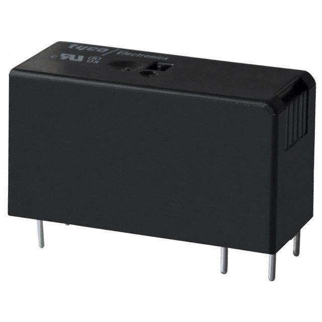
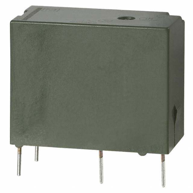
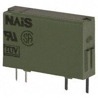
ICGOO在线商城 > 继电器 > 功率继电器,高于 2 A > ALDP112W
- 型号: ALDP112W
- 制造商: Panasonic Corporation
- 库位|库存: xxxx|xxxx
- 要求:
| 数量阶梯 | 香港交货 | 国内含税 |
| +xxxx | $xxxx | ¥xxxx |
查看当月历史价格
查看今年历史价格
ALDP112W产品简介:
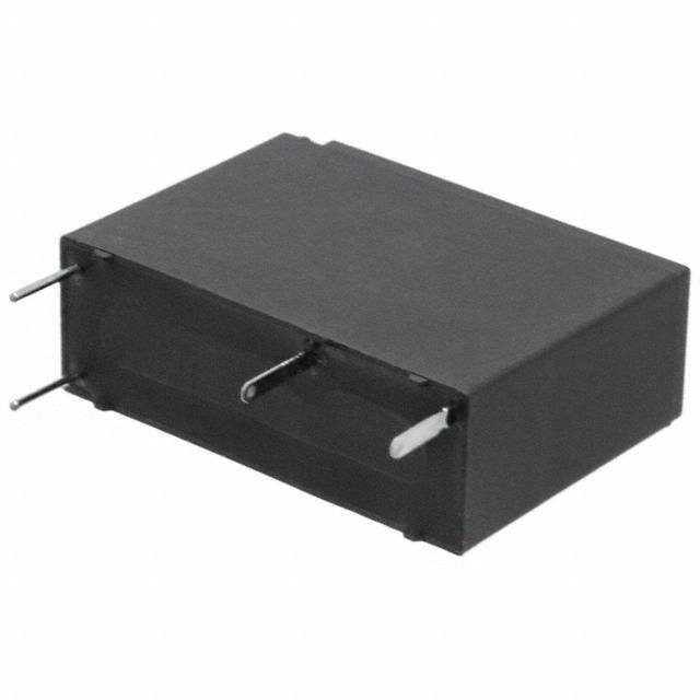
ICGOO电子元器件商城为您提供ALDP112W由Panasonic Corporation设计生产,在icgoo商城现货销售,并且可以通过原厂、代理商等渠道进行代购。 ALDP112W价格参考。Panasonic CorporationALDP112W封装/规格:功率继电器,高于 2 A, 通用 继电器 SPST-NO(1 Form A) 12VDC 线圈 通孔。您可以下载ALDP112W参考资料、Datasheet数据手册功能说明书,资料中有ALDP112W 详细功能的应用电路图电压和使用方法及教程。
Panasonic Electric Works 生产的 ALDP112W 功率继电器是一款额定电流高于 2 A 的高性能继电器,适用于多种工业和商业应用场景。以下是该型号继电器的主要应用场景:

 1. 工业自动化控制系统
ALDP112W 继电器广泛应用于各种工业自动化设备中,如生产线、装配线、机器人控制等。它能够承受较高的电流负载,确保在频繁开关操作下仍能稳定工作。该继电器常用于控制电机、电磁阀、加热器等大功率设备的启停,帮助实现精确的自动化控制。

 2. 电力分配与保护系统
在电力分配系统中,ALDP112W 可以用于配电箱、断路器等设备中,起到电路保护的作用。它能够在过载或短路情况下迅速切断电路,防止设备损坏或火灾事故的发生。此外,它还可以用于电力监控系统中,实时监测电流变化并做出相应动作。

 3. 家用电器
虽然 ALDP112W 主要应用于工业领域,但它也可以用于一些高端家用电器中,如空调、洗衣机、烘干机等。这些家电通常需要较大的启动电流,而 ALDP112W 的高电流承载能力可以确保其在长时间使用过程中保持稳定,延长设备寿命。

 4. 照明控制系统
在大型建筑或公共场所的照明系统中,ALDP112W 可用于控制高功率灯具的开关。例如,在商场、机场、体育馆等场所,照明系统需要根据时间和需求进行智能控制,ALDP112W 能够满足这种需求,提供可靠的开关控制功能。

 5. 新能源应用
随着新能源技术的发展,ALDP112W 在太阳能逆变器、风力发电控制器等新能源设备中也得到了广泛应用。它能够处理较大的电流波动,确保能量转换系统的高效运行,并且具备良好的抗干扰性能,适应复杂的电磁环境。

总之,Panasonic Electric Works 的 ALDP112W 功率继电器凭借其高电流承载能力和稳定性,成为众多行业中不可或缺的关键组件,适用于需要可靠电气控制的各种场合。
| 参数 | 数值 |
| 产品目录 | |
| 描述 | RELAY GEN PURPOSE SPST 5A 12V通用继电器 LD-P Relay |
| 产品分类 | |
| 品牌 | Panasonic Industrial Devices |
| 产品手册 | |
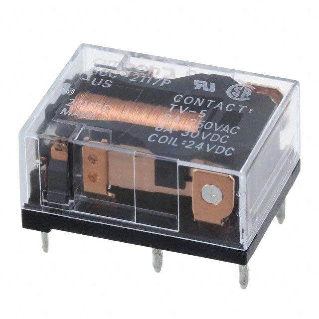
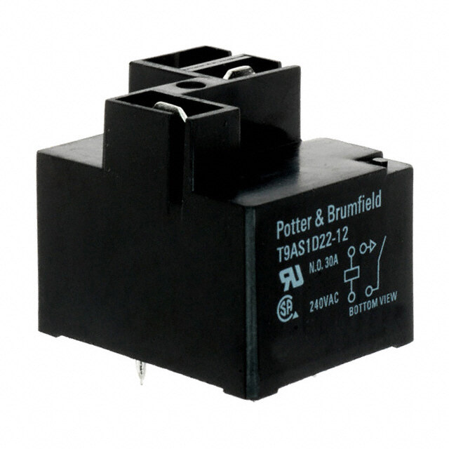
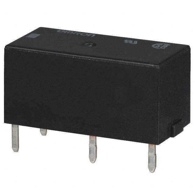
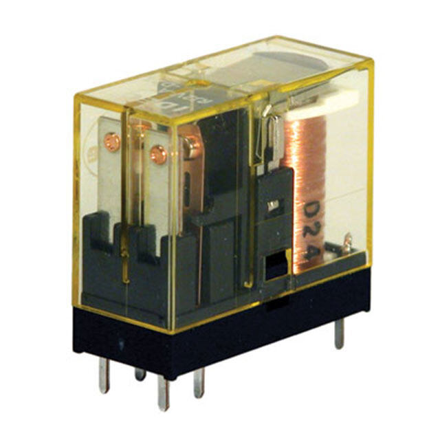
| 产品图片 |
|
| 产品系列 | 通用继电器,Panasonic Industrial Devices ALDP112WALDP |
| 数据手册 | |
| 产品型号 | ALDP112W |
| rohs | 无铅 / 符合限制有害物质指令(RoHS)规范要求 |
| 产品 | HVAC Relays |
| 产品种类 | 通用继电器 |
| 关闭电压(最小值) | 0.6 VDC |
| 其它名称 | 255-3589 |
| 其它有关文件 | |
| 切换电压 | 277 V |
| 功耗 | 200 mW |
| 包装 | 托盘 |
| 商标 | Panasonic Industrial Devices |
| 安装类型 | 通孔 |
| 安装风格 | Through Hole |
| 宽度 | 7.2 mm |
| 导通电压(最大值) | 9 VDC |
| 封装 | Bulk |
| 工作时间 | 10ms |
| 工作温度 | -40°C ~ 85°C |
| 工厂包装数量 | 100 |
| 开关电压 | 277VAC - 最小值 |
| 标准包装 | 100 |
| 特性 | - |
| 端子类型 | PC 引脚 |
| 端接类型 | Solder Pin |
| 类型 | Slim Form |
| 系列 | LD-P Relays |
| 线圈功率 | 200 mW |
| 线圈电压 | 12 V |
| 线圈电流 | 16.7mA |
| 线圈电阻 | 720 Ohms |
| 线圈端接 | Solder Pin |
| 线圈类型 | Non-Latching |
| 继电器类型 | 通用 |
| 触头外形 | SPST-NO(1 A 型) |
| 触头材料 | 银镍(AgNi) |
| 触点形式 | SPST (1 Form A) |
| 触点材料 | Silver Nickel |
| 触点电流额定值 | 5 A |
| 释放时间 | 10ms |
| 长度 | 20.5 mm |
| 额定接触(电流) | 5A |
| 高度 | 15.3 mm |


- 商务部:美国ITC正式对集成电路等产品启动337调查
- 曝三星4nm工艺存在良率问题 高通将骁龙8 Gen1或转产台积电
- 太阳诱电将投资9.5亿元在常州建新厂生产MLCC 预计2023年完工
- 英特尔发布欧洲新工厂建设计划 深化IDM 2.0 战略
- 台积电先进制程称霸业界 有大客户加持明年业绩稳了
- 达到5530亿美元!SIA预计今年全球半导体销售额将创下新高
- 英特尔拟将自动驾驶子公司Mobileye上市 估值或超500亿美元
- 三星加码芯片和SET,合并消费电子和移动部门,撤换高东真等 CEO
- 三星电子宣布重大人事变动 还合并消费电子和移动部门
- 海关总署:前11个月进口集成电路产品价值2.52万亿元 增长14.8%
.jpg)

PDF Datasheet 数据手册内容提取
Slim (7.2mm .283inch), LD-P RELAYS (ALDP) 1 Form A 5A power relay FEATURES TYPICAL APPLICATIONS 7.2 1.Nominal switching capacity: • Boilers 20.5 .283 5A 277V AC • Air conditioner .807 2.Excellent heat resistance and • Refrigerator 15.3 tracking performance • Hot water units .602 EN60695 (GWT2-11, GWFI2-12, GWIT2-13) data • Microwave ovens available • Fan heaters (Please consult us for details.) 3.Slim type: 20.5 (L) × 7.2 (W) × 15.3 mm inch (H) mm .807 (L) × .283 (W) × .602 (H) inch 4.Class “B” and “F” coil is available 5.Contact rating at 105°C 221°F is RoHS compliant approved by UL/C-UL and VDE (Class “F” coil only) Protective construction: Sealed type 6.Clearance and Creepage distance between contact and coil min. 6 mm .236 inch 7.High surge voltage: 10,000 V between contact and coil ORDERING INFORMATION ALDP 1 W LD-P relay Contact arrangement 1: 1 Form A Rated voltage (DC) 05: 5V, 06: 6V, 09: 9V, 12: 12V, 18: 18V, 24: 24V Packing style W: Carton packing Notes:1. Class “B” and “F” coil is available (Class “B”: ALDP1B**W, Class “F”: ALDP1F**W) 2. The “W” at the end of the part number only appears on the inner and outer packaging. It does not appear on the relay itself. Please consult with our sales office on a tube packing type. TYPES Standard packing Contact arrangement Rated voltage Part No. Carton Case 5V DC ALDP105W 6V DC ALDP106W 9V DC ALDP109W 1 Form A 100 pcs. 500 pcs. 12V DC ALDP112W 18V DC ALDP118W 24V DC ALDP124W –1– ASCTB193E 201702-T
LD-P (ALDP1) RATING 1. Coil data Pick-up voltage*1 Drop-out voltage*1 Rated operating current Coil resistance Max. allowable voltage Rated voltage (at 20°C 68°F) (at 20°C 68°F) (DC, ±10%, at 20°C 68°F) (±10%, at 20°C 68°F) Rated operating power (at 20°C 68°F) 5V DC 40.0mA 125Ω 6V DC 33.3mA 180Ω 9V DC 75%V or less of 5%V or more of 22.2mA 405Ω 180%V of nominal voltage nominal voltage 200mW 12V DC (Initial) (Initial) 16.7mA 720Ω rated voltage*2 18V DC 11.1mA 1,620Ω 24V DC 8.3mA 2,880Ω Notes:*1.Square, pulse drive *2.Maximum allowable voltage is the maximum voltage which can satisfy the coil temperature rise value. 2. Specifications Characteristics Item Specifications Arrangement 1 Form A Contact resistance (initial) Max. 100 mΩ (By voltage drop 6 V DC 1A) Contact material AgNi type Contact rating (resistive) 5A 277V AC, 3A 30V DC Contact data Max. switching power (resistive) 1,385VA, 90W Max. switching voltage 277V AC, 30V DC Max. switching current 5A (AC), 3A (DC) Min. switching load (reference value)*1 100mA 5V DC Insulation resistance (initial) Min. 1,000MΩ (at 500V DC) Measured portion is the same as the case of dielectric voltage. Between open contacts 750 Vrms for 1 min. (detection current: 10 mA) Dielectric strength (initial) Between contact and coil 4,000 Vrms for 1 min. (detection current: 10 mA) Surge withstand voltage Between contact and coil 10,000 V (initial)*2 Operate time (initial) Max. 10 ms (at rated voltage, at 20°C 68°F, excluding contact bounce time) Release time (initial) Max. 10 ms (at rated voltage, at 20°C 68°F, excluding contact bounce time, with diode) Functional 300 m/s2 (half-wave pulse of sine wave: 11 ms; detection time: 10μs) Shock resistance Destructive 1,000 m/s2 (half-wave pulse of sine wave: 6 ms) Functional 10 to 55 Hz at double amplitude of 1.5 mm (Detection time: 10μs) Vibration resistance Destructive 10 to 55 Hz at double amplitude of 1.5 mm Expected life Mechanical Min. 5×10⁶ (at 180 times/min.) Conditions for operation, transport and Ambient temperature: –40 to +85°C –40 to +185°F Conditions storage*3 Humidity: 5 to 85% R.H. (Not freezing and condensing at low temperature) Unit weight Approx. 4 g .14 oz Notes:*1.This value can change due to the switching frequency, environmental conditions, and desired reliability level, therefore it is recommended to check this with the actual load. *2.Wave is standard shock voltage of ±1.2×50μs according to JEC-212-1981 *3.The upper limit of the ambient temperature is the maximum temperature that can satisfy the coil temperature rise value. Refer to Usage, transport and storage conditions in NOTES. 3. Expected electrical life Condition: Resistive, at 20 times/min. Type Switching capacity Number of operations 5A 125V AC Min. 2×10⁵ 1 Form A 5A 250V AC Min. 105 3A 30V DC Min. 105 REFERENCE DATA 1. Max. switching capacity 2. Life curve 3. Coil temperature rise (Ave.) Sample: ALDP112, 6 pcs. Point measured: inside the coil Contact current: 0 A, 5 A 10 100 50 *at room temperature 125V AC resistive load ontact current, A 51 AC resistive load ×4Life, 10 10 250V AC resistive load °mperature rise, C 4300 5088AA55°°**CC 50AA C Te 20 0.1 1 10 10 100 0 1 2 3 4 5 6 80 100 120 140 Contact voltage, V Contact current, A Coil applied voltage, %V –2– ASCTB193E 201702-T
LD-P (ALDP1) 4-(1). Operate time 4-(2). Release time (without diode) 4-(3). Release time (with diode) Sample: ALDP112, 30 pcs. Sample: ALDP112, 30 pcs. Sample: ALDP112, 30 pcs. 10 10 10 8 8 8 ms ms ms me, me, me, Operate ti 64 Release ti 64 Release ti 64 MMainx.. Max. Min. 2 2 Max. 2 Min. 0 0 0 60 80 100 120 140 60 80 100 120 140 60 80 100 120 140 Coil applied voltage, %V Coil applied voltage, %V Coil applied voltage, %V 5. Electrical life test Change of pick-up and drop-out voltage Change of contact resistance (5A 250V AC Resistive load) 10 100 Sample: ALDP112, 6 pcs. V O(COpi2rNe5c0:ruOVa itAFti:oCFn =fr 1e.q5use:1n.c5ys: )20 tim1e2sV/ DmCin. Contact welding detection and Mis-contacting detection circuit Pick-up and drop-out voltage, 987654321 DPriocpk--uopu tv vooltlataggee MMMMaiainnxx.... ΩContact resistance, m 987654321000000000 MMainx.. 0 0 0 10 0 10 No. of operations, ×104 No. of operations, ×104 DIMENSIONS (mm inch) The CAD data of the products with a CAD Data mark can be downloaded from: http://industrial.panasonic.com/ac/e/ CAD Data External dimensions PC board pattern (Bottom view) MMaaxx.. 2.800.57 MMaaxx.. 7.2.283 ((1.0.1455)) 1.415.53 .72.706 44--1.0.14 3d idai.a. Max. 15.3 0.0.416 Max. .602 4.7 (1.05) .185 (.041) 3.4 Tolerance: ±0.1 ±.004 .134 0.4 dia. 0.2 0.8 .016 dia. .008 0.2 .031 .008 1.0.0451 1.415.53 .72.706 .41.875 1.0.1455 Schematic (Bottom view) COM NO COIL Dimension: General tolerance Less than 1mm .039inch: ±0.1 ±.004 Min. 1mm .039inch less than 3mm .118 inch: ±0.2 ±.008 Min. 3mm .118 inch: ±0.3 ±.012 –3– ASCTB193E 201702-T
LD-P (ALDP1) SAFETY STANDARDS UL/C-UL(Recognized)*1 VDE (Certified) CQC File No. Rating Cycles Temp. File No. Rating Cycles Temp. File No. Rating Cycle Temp. 5A 277V AC 85°C 5A 250V AC 85°C 85°C Resistive 105 185°F (cosφ=1.0) 105 185°F 5A 250V AC 104 185°F 5A 30V DC 5A 30V DC 25°C Resistive 105 – (0ms) 104 77°F — — — 6A 277A AC 5 × 10⁴ – 5(cAo s2φ5=01V. 0A)C*2 5 × 10⁴ 120251°°CF — — — E43028 3GAe n2e7r7aVl u AsCe 12 × 104 18855°°CF 40014384 — — — CQC10002048611 — — — 5RAe s2is7t7ivVe *A2C 5 × 10⁴ 120251°°CF — — — — — — 85°C Pilot duty, C300 105 185°F — — — — — — Pilot duty, 85°C 0.65A 277V AC 105 185°F — — — — — — (Inrush 6.5A) Notes:*1.CSA standard: Certified by C-UL *2.For Insulation Class F models only (Coil class F) INSULATION CHARACTERISTICS (IEC61810-1) Item Characteristics Clearance/Creepage distance (IEC61810-1) Min. 5.5mm/5.5mm Category of protection (IEC61810-1) RTIII GWT (IEC60335-1) GWFI850/GWT750 2s (base)/GWIT775 (cover) Tracking resistance (IEC60112) PTI175 Insulation material group IIIa Over voltage category III III Impulse Withstand Voltage 4 kV 6 kV Rated voltage 250V 250V Pollution degree 3 2 Type of insulation (Between contact and coil) Basic Insulation Reinforced Insulation Type of insulation (Between open contact) Micro Disconnection *EN/IEC VDE Certified NOTES 1. For cautions for use, please read 3. Maximum Applied Voltage and “GENERAL APPLICATION Temperature Rise GUIDELINES”. Proper usage requires that the rated 2. Certification voltage be impressed on the coil. Note, UL/C-UL and VDE certified ratings are however, that if a voltage greater than or displayed on the packaging box. equal to the maximum applied voltage is (On the relay, only the certification marks impressed on the coil, the coil may burn are shown and not the certified ratings. or its layers short due to the temperature Please refer to the product specification rise. Furthermore, do not exceed the diagrams to see what is stamped.) usable ambient temperature range listed in the catalog. –4– ASCTB193E 201702-T
None
Mouser Electronics Authorized Distributor Click to View Pricing, Inventory, Delivery & Lifecycle Information: P anasonic: ALDP105W ALDP106W ALDP109W ALDP112W ALDP118W ALDP124W
 Datasheet下载

