ICGOO在线商城 > 集成电路(IC) > 时钟/计时 - 可编程计时器和振荡器 > ALD2502PBL
- 型号: ALD2502PBL
- 制造商: Advanced Linear Devices
- 库位|库存: xxxx|xxxx
- 要求:
| 数量阶梯 | 香港交货 | 国内含税 |
| +xxxx | $xxxx | ¥xxxx |
查看当月历史价格
查看今年历史价格
ALD2502PBL产品简介:
ICGOO电子元器件商城为您提供ALD2502PBL由Advanced Linear Devices设计生产,在icgoo商城现货销售,并且可以通过原厂、代理商等渠道进行代购。 ALD2502PBL价格参考。Advanced Linear DevicesALD2502PBL封装/规格:时钟/计时 - 可编程计时器和振荡器, 555 Type, Timer/Oscillator (Dual) IC 2.5MHz 14-PDIP。您可以下载ALD2502PBL参考资料、Datasheet数据手册功能说明书,资料中有ALD2502PBL 详细功能的应用电路图电压和使用方法及教程。
| 参数 | 数值 |
| 产品目录 | 集成电路 (IC)半导体 |
| 描述 | IC OSC TIMER DUAL 2.5MHZ 14DIP计时器和支持产品 Dual/Micropwr 2-12V |
| 产品分类 | |
| 品牌 | Advanced Linear Devices Inc |
| 产品手册 | |
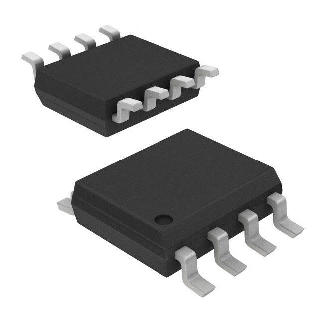
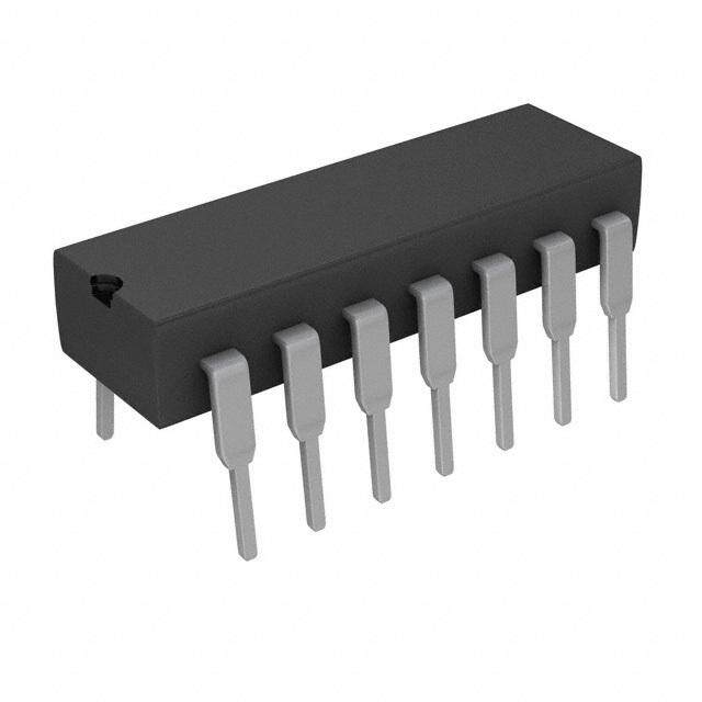
| 产品图片 |
|
| rohs | 符合RoHS无铅 / 符合限制有害物质指令(RoHS)规范要求 |
| 产品系列 | 时钟和计时器IC,计时器和支持产品,Advanced Linear Devices ALD2502PBL- |
| mouser_ship_limit | 根据美国政府的出口法规规定,Mouser无法将此产品销售到您所在的国家。 |
| 数据手册 | |
| 产品型号 | ALD2502PBL |
| 产品种类 | 计时器和支持产品 |
| 供应商器件封装 | 14-PDIP |
| 其它名称 | 1014-1128 |
| 内部定时器数量 | 2 |
| 包装 | 管件 |
| 商标 | Advanced Linear Devices |
| 安装类型 | 通孔 |
| 安装风格 | Through Hole |
| 封装/外壳 | 14-DIP(0.300",7.62mm) |
| 封装/箱体 | PDIP-14 |
| 工作温度 | 0°C ~ 70°C |
| 工厂包装数量 | 50 |
| 最大功率耗散 | 600 mW |
| 最大工作温度 | + 70 C |
| 最小工作温度 | 0 C |
| 标准包装 | 50 |
| 电压-电源 | 2 V ~ 12 V |
| 电流-电源 | 100µA |
| 电源电压-最大 | 12 V |
| 电源电压-最小 | 2 V |
| 类型 | Standard |
| 系列 | ALD2502P |
| 计数 | - |
| 频率 | 2.5MHz |


PDF Datasheet 数据手册内容提取
ADVANCED LINEAR DEVICES, INC. ALD1502/ALD2502 SINGLE/DUAL PRECISION HIGH SPEED MICROPOWER TIMER GENERAL DESCRIPTION APPLICATIONS The ALD1502/ALD2502 timers are high performance single/dual mono- • High speed one-shot (monostable) lithic timing circuits built with advanced silicon gate CMOS technology. pulse generation They offer the benefits of high input impedance, thereby allowing • Precision timing smaller timing capacitors and a longer timing cycle; high speed, with • Sequential timing typical cycle time of 400ns; low power dissipation for battery operated • Long delay timer environment; reduced supply current spikes, allowing smaller and • Pulse width and pulse position lower cost decoupling capacitors. modulation • Missing pulse detector Each timer is capable of producing accurate time delays and oscilla- tions in both monostable and astable operation, and operates in the • Frequency divider one-shot (monostable) mode or 50% duty cycle free running oscillation • Synchronized timer mode with a single resistor and one capacitor. The inputs and outputs are fully compatible with CMOS, NMOS or TTL logic. PIN CONFIGURATION There are three matched internal resistors (approximately 200KΩ each) that set the threshold and trigger levels at two-thirds and one-third ALD1502 respectively of V+. These levels can be adjusted by using the control GND 1 8 V+ terminal. When the trigger input is below the trigger level, the output is in the high state and sourcing 2mA. When the threshold input is above TRIG 2 7 DISC the threshold level at the same time the trigger input is above the trigger OUT 3 6 THRES level, the internal flip-flop is reset, the output goes to the low state and RST 4 5 CONT sinks up to 10mA. The reset input overrides all other inputs and when it is active (reset voltage less than 1V), the output is in the low state. SAL, PAL, DA PACKAGES FEATURES ALD2502 DSC1 1 14 V+ • High speed operation -- 2.5MHz typical oscillation at 5V • High discharge sinking current of 80mA at 5V THRES1 2 13 DSC2 • Guaranteed low operating supply voltage of 2V to 12V CONT1 3 12 THRES2 • Functional equivalent to and same pin-out as NE555/NE556 RST1 4 11 CONT2 with greatly expanded high and low frequency ranges OUT1 5 10 RST2 • High speed, low power, monolithic CMOS technology TRIG1 6 9 OUT2 • Low supply current: 50(cid:181)A typical for ALD1502 GND 7 8 TRIG2 and100(cid:181)A typical for ALD2502 • Extremely low trigger, threshold and reset currents: 10pA typical SBL, PBL, DB PACKAGES • Operates in both monostable and astable modes • Fixed 50% duty cycle or adjustable duty cycle • CMOS, NMOS and TTL compatible input/output BLOCK DIAGRAM (EACH TIMER) • Low supply current spikes V+ ORDERING INFORMATION (“L” suffix denotes lead-free (RoHS)) (8) RESET Operating Temperature Range * (4) THRESHOLD 0(cid:176)C to +70(cid:176)C 0(cid:176)C to +70(cid:176)C -55(cid:176)C to +125(cid:176)C (6) R R CONTROL 8-Pin Small Outline 8-Pin Plastic 8-Pin CERDIP (5) R OUTPUT (3) Package (SOIC) DIP Package Package ALD1502SAL ALD1502PAL ALD1502DA S DISCHARGE TRIGGER (7) (2) R 14-Pin Small Outline 14-Pin Plastic 14-Pin CERDIP Package (SOIC) DIP Package Package ALD2502SBL ALD2502PBL ALD2502DB GND * Contact factory for leaded (non-RoHS) or high temperature versions. (1) Rev 2.0 ©2010 Advanced Linear Devices, Inc. 415 Tasman Drive, Sunnyvale, CA 94089-1706 Tel: (408) 747-1155 Fax: (408) 747-1286 www.aldinc.com
ABSOLUTE MAXIMUM RATINGS Supply voltage, V+ 13.2V Input voltage range -0.3V to V+ +0.3V Power dissipation 600 mW Operating temperature range SAL, SBL, PAL, PBL packages 0(cid:176)C to + 70(cid:176)C DA, DB packages -55(cid:176)C to +125(cid:176)C Storage temperature range -65(cid:176)C to +150(cid:176)C Lead temperature, 10 seconds +260(cid:176)C OPERATING ELECTRICAL CHARACTERISTICS TA = 25oC V+= +5V unless otherwise specified Parameter Symbol Min Typ Max Unit Test Conditions Supply Voltage V+ 2 12 V Supply Current ALD1502 IS 50 90 (cid:181)A Outputs Unloaded Supply Current ALD2502 IS 100 180 (cid:181)A Timing error / Astable mode terr 1.0 2.2 % C = 0.1(cid:181)F Initial Accuracy Drift with Temperature 1 ∆t/∆T 10.0 ppm/(cid:176)C RA = 1KΩ Drift with Supply Voltage 1 ∆t/∆V+ 0.2 %/V RB = 1KΩ Threshold Voltage VTH 3.233 3.333 3.433 V Trigger Voltage VTRIG 1.567 1.667 1.767 V Trigger Current 2 ITRIG .01 0.4 nA Reset Voltage VRST 0.4 0.7 1.0 V Reset Current 2 IRST .01 0.4 nA Threshold Current 2 ITH .01 0.4 nA Control Voltage Level VCONT 3.233 3.333 3.433 V Output Voltage Drop (Low) VOL 0.2 0.4 V ISINK = 10mA Output Voltage Drop (High) VOH 4.2 4.6 V ISOURCE = -2mA Rise Time of Output 1 tr 10 20 ns RL = 10MΩ Fall Time of Output 1 tf 10 20 ns CL = 10pF Discharge Transistor IDL .01 nA Leakage Current Discharge Voltage Drop VDISC 0.5 1.0 V I DISCHARGE = 80mA 0.2 0.4 V I DISCHARGE = 30mA Maximum Frequency RA = 470Ω Astable Mode fMAX 1.5 2.5 MHz RB = 200Ω CT =100pF Minimum Trigger Pulse Width1 tTRIG 50 100 ns Notes: 1 Sample tested parameters. 2 Consists of junction leakage currents with strong temperature dependence. ALD1502/ALD2502 Advanced Linear Devices 2 of 10
TYPICAL PERFORMANCE CHARACTERISTICS DISCHARGE OUTPUT SINK CURRENT AS A MINIMUM PULSE WIDTH FUNCTION OF DISCHARGE LOW VOLTAGE REQUIRED FOR TRIGGERING A) 100 800 NT (m 50 TA = 25(cid:176)C V+ = 12V V+ = 5V H (ns) 700 TA = 25(cid:176)C E 20 T 600 URR 10 V+ = 2V WID 500 GE SINK C 521...000 M PULSE 430000 VVV+++ = == 15 22VVV SCHAR 00..25 MINIMU 210000 DI 0.1 0 0.01 0.02 0.05 0.1 0.2 0.5 1.0 0 10 20 30 40 DISCHARGE LOW VOLTAGE (V) LOWEST VOLTAGE LEVEL OF TRIGGER PULSE ( % VDD ) FREE RUNNING FREQUENCY AS FREQUENCY CHANGE IN THE ASTABLE A FUNCTION OF RA, RB AND C MODE AS A FUNCTION OF SUPPLY VOLTAGE 10 mF +4 1 mF ( RA- 2RB) TA = 25(cid:176)C %) +3 100 (cid:181)F E ( +2 G E N C 10 (cid:181)F A +1 N H CITA 1 (cid:181)F 101KΩ CY C 0 CAPA 110100 nnnFFF 1001M0M1MΩΩ100KΩKΩ FREQUEN ---231 Ω 100 pF -4 0.1 1.0 10 100 1K 10K 100K1M 10M 100M 0 2 4 6 8 10 12 FREQUENCY (Hz) SUPPLY VOLTAGE (V) TIME DELAY IN THE MONOSTABLE MODE SUPPLY CURRENT AS A FUNCTION OF AS A FUNCTION OF RA AND C SUPPLY VOLTAGE 10 mF 100 1 mF TA = 25(cid:176)C RA A) 90 CAPACITANCE 11101000100 (cid:181)n(cid:181)n(cid:181)FFFFF 1K1Ω0K1Ω001KMΩ1Ω01M0Ω0M ΩΩ UPPLY CURRENT ((cid:181) 653874000000 TTTAAA === ++- 284050(cid:176)(cid:176)(cid:176)CCC G S 20 1 1 nF 10 100 pF 0 100ns 1(cid:181)s10(cid:181)s100(cid:181)s1ms10ms100ms1s 10s 100s 0 2 4 6 8 10 12 TIME DELAY SUPPLY VOLTAGE (V) ALD1502/ALD2502 Advanced Linear Devices 3 of 10
TYPICAL PERFORMANCE CHARACTERISTICS (cont'd) OUTPUT SINK CURRENT AS A OUTPUT SOURCE CURRENT AS A FUNCTION OF OUTPUT VOLTAGE FUNCTION OF OUTPUT VOLTAGE 100 A) -0.1 NT (mA) 5200 TA = 25(cid:176)C V+ = 12V V+ = 5V RENT (m --00..52 VVV+++ === 215V2VV RE 10 UR -1.0 R C U 5.0 V+ = 2V E -2.0 C C NK 2.0 UR -5.0 OUTPUT SI 100...025 OUTPUT SO ---152000 0.1 -100(cid:31) 0.01 0.02 0.05 0.1 0.2 0.5 1.0 -1.0 -0.5 -0.2 -0.1 -0.05 -0.02 -0.01 OUTPUT VOLTAGE (V) OUTPUT VOLTAGE (V) (REFERENCED TO V+) TYPICAL APPLICATIONS (EACH TIMER) ASTABLE MODE OPERATION ASTABLE MODE OPERATION 50% DUTY CYCLE (FREE RUNNING OSCILLATOR) V+ V+ 1 8 1 8 0.1(cid:181)F RA 0.1(cid:181)F 2 7 2 7 R RB 3 6 3 6 V+ C V+ C 4 5 4 5 Frequency f = 1/ (1.4 RC) Frequency f = 1.46 / (RA + 2RB)C Duty Cycle DC = RB / (RA + 2RB) MONOSTABLE MODE OPERATION (ONE SHOT PULSE) Pulse Delay td = 1.1 RC V+ 1 8 0.1(cid:181)F R TRIGGER 2 7 INPUT DELAYED PULSE 3 6 OUTPUT C 4 5 RESET ALD1502/ALD2502 Advanced Linear Devices 4 of 10
SOIC-8 PACKAGE DRAWING 8 Pin Plastic SOIC Package E Millimeters Inches Dim Min Max Min Max A 1.35 1.75 0.053 0.069 A1 0.10 0.25 0.004 0.010 S (45(cid:176)) b 0.35 0.45 0.014 0.018 C 0.18 0.25 0.007 0.010 D-8 4.69 5.00 0.185 0.196 D E 3.50 4.05 0.140 0.160 e 1.27 BSC 0.050 BSC H 5.70 6.30 0.224 0.248 A L 0.60 0.937 0.024 0.037 ø 0(cid:176) 8(cid:176) 0(cid:176) 8(cid:176) e A1 S 0.25 0.50 0.010 0.020 b (cid:31) S (45(cid:176)) H C L ø ALD1502/ALD2502 Advanced Linear Devices 5 of 10
SOIC-14 PACKAGE DRAWING 14 Pin Plastic SOIC Package Millimeters Inches Dim Min Max Min Max E A 1.35 1.75 0.053 0.069 A1 0.10 0.25 0.004 0.010 b 0.35 0.45 0.014 0.018 S (45(cid:176)) C 0.18 0.25 0.007 0.010 D-14 8.55 8.75 0.336 0.345 E 3.50 4.05 0.140 0.160 e 1.27 BSC (cid:31) (cid:31) 0.050 BSC (cid:31) D H 5.70 6.30 0.224 0.248 L 0.60 0.937 0.024 0.037 ø 0(cid:176) 8(cid:176) 0(cid:176) 8(cid:176) S 0.25 0.50 0.010 0.020 A (cid:31) e A1 b S (45(cid:176)) H C L ø ALD1502/ALD2502 Advanced Linear Devices 6 of 10
PDIP-8 PACKAGE DRAWING 8 Pin Plastic DIP Package Millimeters Inches Dim Min Max Min Max E E1 A 3.81 5.08 0.105 0.200 A1 0.38 1.27 0.015 0.050 A2 1.27 2.03 0.050 0.080 b 0.89 1.65 0.035 0.065 b1 0.38 0.51 0.015 0.020 c 0.20 0.30 0.008 0.012 D-8 9.40 11.68 0.370 0.460 D S E 5.59 7.11 0.220 0.280 E1 7.62 8.26 0.300 0.325 A2 A e 2.29 2.79 0.090 0.110 A1 L e1 7.37 7.87 0.290 0.310 b e L 2.79 3.81 0.110 0.150 S-8 1.02 2.03 0.040 0.080 ø b1 0(cid:176) 15(cid:176) 0(cid:176) 15(cid:176) c e1 ø ALD1502/ALD2502 Advanced Linear Devices 7 of 10
PDIP-14 PACKAGE DRAWING 14 Pin Plastic DIP Package Millimeters Inches Dim Min Max Min Max A 3.81 5.08 0.105 0.200 E E1 A1 0.38 1.27 0.015 0.050 A2 1.27 2.03 0.050 0.080 b 0.89 1.65 0.035 0.065 b1 0.38 0.51 0.015 0.020 c 0.20 0.30 0.008 0.012 D-14 17.27 19.30 0.680 0.760 E 5.59 7.11 0.220 0.280 E1 7.62 8.26 0.300 0.325 D S e 2.29 2.79 0.090 0.110 e1 7.37 7.87 0.290 0.310 L 2.79 3.81 0.110 0.150 A2 A S-14 1.02 2.03 0.040 0.080 A1 L ø 0(cid:176) 15(cid:176) 0(cid:176) 15(cid:176) b e b1 c e1 ø ALD1502/ALD2502 Advanced Linear Devices 8 of 10
CERDIP-8 PACKAGE DRAWING 8 Pin CERDIP Package E E1 Millimeters Inches Dim Min Max Min Max A 3.55 5.08 0.140 0.200 D A1 1.27 2.16 0.050 0.085 b 0.97 1.65 0.038 0.065 b1 0.36 0.58 0.014 0.023 s A1 C 0.20 0.38 0.008 0.015 D-8 -- 10.29 -- 0.405 A E 5.59 7.87 0.220 0.310 E1 7.73 8.26 0.290 0.325 L L2 L1 e (cid:31) 2.54 BSC 0.100 BSC b e1 (cid:31) 7.62 BSC 0.300 BSC b1 L 3.81 5.08 0.150 0.200 L1 3.18 -- 0.125 -- e L2 0.38 1.78 0.015 0.070 S -- 2.49 -- 0.098 Ø 0(cid:176) 15(cid:176) 0(cid:176) 15(cid:176) C ø e1 ALD1502/ALD2502 Advanced Linear Devices 9 of 10
CERDIP-14 PACKAGE DRAWING 14 Pin CERDIP Package Millimeters Inches Dim Min Max Min Max A 3.55(cid:31) 5.08(cid:31) 0.140(cid:31) 0.200(cid:31) E E1 A1 1.27(cid:31) 2.16(cid:31) 0.050(cid:31) 0.085(cid:31) b 0.97(cid:31) 1.65(cid:31) 0.038(cid:31) 0.065(cid:31) b1 0.36(cid:31) 0.58(cid:31) 0.014(cid:31) 0.023(cid:31) C 0.20(cid:31) 0.38(cid:31) 0.008(cid:31) 0.015(cid:31) D-14 --(cid:31) 19.94(cid:31) --(cid:31) 0.785(cid:31) D E 5.59(cid:31) 7.87(cid:31) 0.220(cid:31) 0.310(cid:31) E1 7.73(cid:31) 8.26(cid:31) 0.290(cid:31) 0.325(cid:31) e (cid:31) 2.54 BSC (cid:31) (cid:31) 0.100 BSC (cid:31) s A1 e1 (cid:31) 7.62 BSC (cid:31) (cid:31) 0.300 BSC (cid:31) A L 3.81(cid:31) 5.08(cid:31) 0.150(cid:31) 0.200(cid:31) L1 3.18(cid:31) --(cid:31) 0.125(cid:31) --(cid:31) L L2 L1 L2 0.38(cid:31) 1.78(cid:31) 0.015(cid:31) 0.070(cid:31) b b1 S --(cid:31) 2.49(cid:31) --(cid:31) 0.098(cid:31) Ø 0(cid:176)(cid:31) 15(cid:176) 0(cid:176) 15(cid:176) e C ø e1 ALD1502/ALD2502 Advanced Linear Devices 10 of 10

 Datasheet下载


