ICGOO在线商城 > 传感器,变送器 > 磁性传感器 - 开关(固态) > AH180N-WG-7

 Datasheet下载
- 型号: AH180N-WG-7
- 制造商: Diodes Inc.
- 库位|库存: xxxx|xxxx
- 要求:
| 数量阶梯 | 香港交货 | 国内含税 |
| +xxxx | $xxxx | ¥xxxx |
查看当月历史价格
查看今年历史价格
AH180N-WG-7产品简介:
ICGOO电子元器件商城为您提供AH180N-WG-7由Diodes Inc.设计生产,在icgoo商城现货销售,并且可以通过原厂、代理商等渠道进行代购。 AH180N-WG-7价格参考。Diodes Inc.AH180N-WG-7封装/规格:磁性传感器 - 开关(固态), Digital Switch Omnipolar Switch Open Drain Hall Effect SC-59-3。您可以下载AH180N-WG-7参考资料、Datasheet数据手册功能说明书,资料中有AH180N-WG-7 详细功能的应用电路图电压和使用方法及教程。
| 参数 | 数值 |
| 产品目录 | |
| 描述 | SENSOR DGTL OMNIPOLAR SWTCH SC59板机接口霍耳效应/磁性传感器 Omni-polar 2.5V-5.5V EDS 6kV Vdd 7V |
| 产品分类 | 磁性传感器 - 霍尔效应,数字开关,线性,罗盘 (IC)磁性传感器 |
| 品牌 | Diodes Incorporated |
| 产品手册 | |
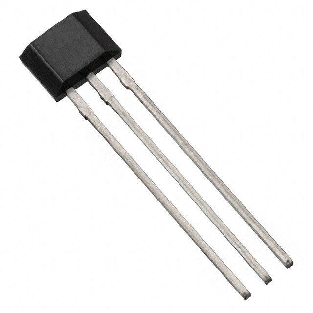
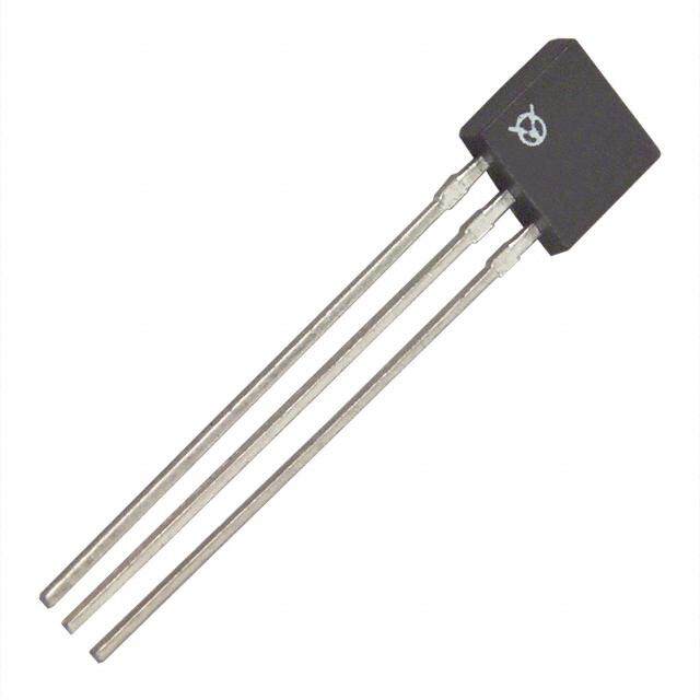
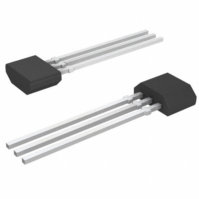
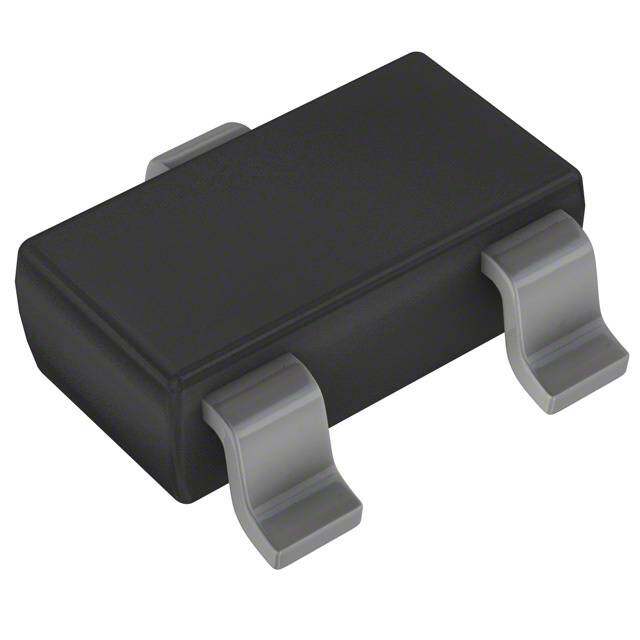
| 产品图片 |
|
| rohs | 符合RoHS无铅 / 符合限制有害物质指令(RoHS)规范要求 |
| 产品系列 | 板机接口霍耳效应/磁性传感器,Diodes Incorporated AH180N-WG-7- |
| 数据手册 | |
| 产品型号 | AH180N-WG-7 |
| RoHS指令信息 | http://diodes.com/download/4349 |
| 产品种类 | 板机接口霍耳效应/磁性传感器 |
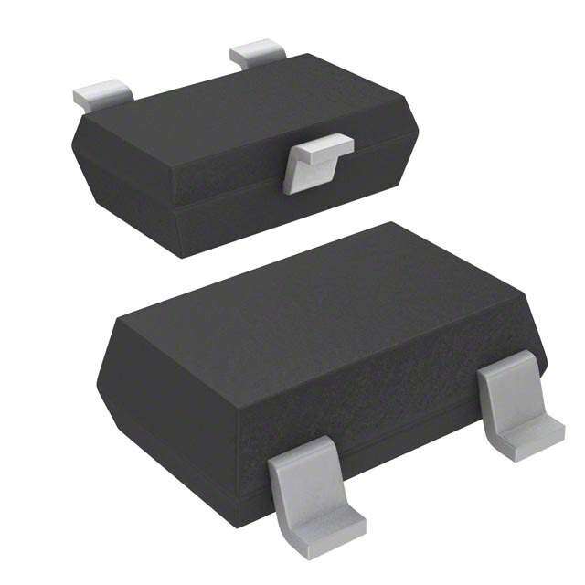
| 供应商器件封装 | SC-59-3 |
| 其它名称 | AH180N-WG-7DICT |
| 功率耗散 | 230 mW |
| 包装 | 剪切带 (CT) |
| 商标 | Diodes Incorporated |
| 安装风格 | SMD/SMT |
| 封装 | Reel |
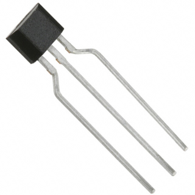
| 封装/外壳 | TO-236-3,SC-59,SOT-23-3 |
| 封装/箱体 | SC-59 |
| 工作温度 | -40°C ~ 85°C |
| 工作点最小值/最大值 | - 50 G, + 50 G |
| 工作电源电压 | 3 V |
| 感应范围 | ±35G 跳闸, ±25G 释放 |
| 最大工作温度 | + 85 C |
| 最大输出电流 | 1 uA |
| 最小/最大释放点(Brp) | + 10 G, - 10 G |
| 最小工作温度 | - 40 C |
| 标准包装 | 1 |
| 特性 | 高灵敏度 |
| 电压-电源 | 2.5 V ~ 5.5 V |
| 电流-电源 | 3mA |
| 电流-输出(最大值) | - |
| 电源电压-最大 | 5.5 V |
| 电源电压-最小 | 2.5 V |
| 电源电流 | 8 uA |
| 类型 | 全极开关 |
| 系列 | AH180W |
| 输出电压 | 0.1 V |
| 输出类型 | 数字式,开漏极 |


- 商务部:美国ITC正式对集成电路等产品启动337调查
- 曝三星4nm工艺存在良率问题 高通将骁龙8 Gen1或转产台积电
- 太阳诱电将投资9.5亿元在常州建新厂生产MLCC 预计2023年完工
- 英特尔发布欧洲新工厂建设计划 深化IDM 2.0 战略
- 台积电先进制程称霸业界 有大客户加持明年业绩稳了
- 达到5530亿美元!SIA预计今年全球半导体销售额将创下新高
- 英特尔拟将自动驾驶子公司Mobileye上市 估值或超500亿美元
- 三星加码芯片和SET,合并消费电子和移动部门,撤换高东真等 CEO
- 三星电子宣布重大人事变动 还合并消费电子和移动部门
- 海关总署:前11个月进口集成电路产品价值2.52万亿元 增长14.8%


PDF Datasheet 数据手册内容提取
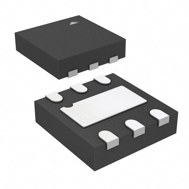
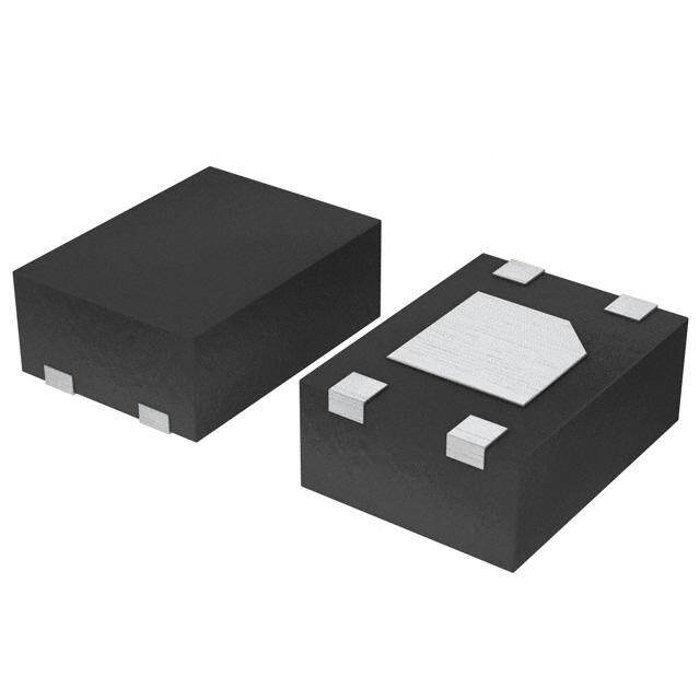
NOT RECOMMENDED FOR NEW DESIGN USE AH1806 AH180N MICROPOWER OMNIPOLAR HALL-EFFECT SWITCH Description Pin Assignments ( Top View ) The AH180N is a high sensitivity, micro power Omnipolar Hall Effect switch IC designed for portable and battery powered equipment such 3. OUTPUT as cellular phones, PDA’ s and portable PC’ s. Based on two sensitive Hall Effect plates and a chopper stabilized architecture the AH180N GND 2. provides a reliable solution over the whole operating range. To 1. VDD support portable and battery powered equipment the design has been optimized to operate over the supply range of 2.5V to 5.5V and SC59 and TSOT23 consumes only 24µA with a supply of 3V. ( Top View ) The single open drain output can switched on with either a North or NC 1 5 OUTPUT South pole of sufficient strength. When the magnetic flux density (B) GND 2 is larger than operate point (Bop) the output is switched on (pulled low). The output is turned off when B becomes lower than the release NC 3 4 VDD point (Brp). The output will remain off when there is no magnetic field. SOT553 Features Applications Omnipolar (North or South pole) Operation Cover Switch in Clam-Shell or Slide Type Cellular Phones High Sensitivity Display Switch for Portable PCs Single Open Drain Output On/Off Switch for PDAs and Digital Cameras Micropower Operation Contact-Less Switch in Consumer Products 2.5V to 5.5V Operating Range Chopper Stabilized Design Provides Superior Temperature Stability Minimal Switch Point Drift Enhanced Immunity to Stress Good RF Noise Immunity -40°C to +85°C Operating Temperature ESD (HBM) > 6KV SC59 (SOT23), TSOT23, and SOT553 Low Profile Packages Totally Lead-Free & Fully RoHS Compliant (Notes 1 & 2) Halogen and Antimony Free. “Green” Device (Note 3) Notes: 1. No purposely added lead. Fully EU Directive 2002/95/EC (RoHS), 2011/65/EU (RoHS 2) & 2015/863/EU (RoHS 3) compliant. 2. See https://www.diodes.com/quality/lead-free/ for more information about Diodes Incorporated’s definitions of Halogen- and Antimony-free, "Green" and Lead-free. 3. Halogen- and Antimony-free "Green” products are defined as those which contain <900ppm bromine, <900ppm chlorine (<1500ppm total Br + Cl) and <1000ppm antimony compounds. AH180N 1 of 8 May 2018 Document number: DS32174 Rev. 5 - 3 www.diodes.com © Diodes Incorporated
NOT RECOMMENDED FOR NEW DESIGN AH180N USE AH1806 Typical Applications Circuit 2.5V to 5.5V V DD R L C OUTPUT AH180N GND Note: C is for power stabilization and to strengthen the noise immunity, the recommended capacitance is 10nF~100nF. RLis the pull-up resistor, the recommended resistance is 10kOhm~100kOhm. Pin Descriptions Pin Name P/I/O Function V P/I Power Supply Input DD GND P/I Ground Output O Output Pin Functional Block Diagram V DD Sleep/awake logic and power switch Hall Plate C anO ceffs Amp Latch OUTPUT llinet g Output Controller GND Hall Plate C anO ceffs Amp Latch llinet g AH180N 2 of 8 May 2018 Document number: DS32174 Rev. 5 - 3 www.diodes.com © Diodes Incorporated
NOT RECOMMENDED FOR NEW DESIGN AH180N USE AH1806 Absolute Maximum Ratings (Note 4) (@TA = +25°C, unless otherwise specified.) Symbol Parameter Ratings Unit V Supply Voltage (Note 5) 7 V DD B Magnetic Flux Density Unlimited SC59 230 P Package Power Dissipation TSOT23 230 mW D SOT553 230 Ts Storage Temperature Range -65 to +150 C T Maximum Junction Temperature +150 C J Notes: 4. Stresses greater than the 'Absolute Maximum Ratings' specified above, may cause permanent damage to the device. These are stress ratings only; functional operation of the device at these or any other conditions exceeding those indicated in this specification is not implied. Device reliability may be affected by exposure to absolute maximum rating conditions for extended periods of time 5. The absolute maximum VDD of 7V is a transient stress rating and is not meant as a functional operating condition. It is not recommended to operate the device at the absolute maximum rated conditions for any period of time. Recommended Operating Conditions (@TA = +25°C, unless otherwise specified.) Symbol Parameter Conditions Rating Unit V Supply Voltage Operating 2.5 to 5.5 V DD TA Operating Temperature Range Operating -40 to +85 C Electrical Characteristics (@TA = +25°C, VDD = 3V, unless otherwise specified.) Symbol Parameter Conditions Min Typ Max Unit V Output On Voltage I = 1mA 0.1 0.3 V OUT OUT Ioff Output Leakage Current VOUT = 5.5V, Output Off <0.1 1 µA Idd(en) Chip Enable, T = +25°C, V = 3V 3 6 mA A DD Chip Enable, T = -40 to +85°C, Idd(en) A 3 12 mA V = 2.5V to 5.5V DD Idd(dis) Chip Disable, T = +25C, V = 3V 5 10 µA A DD Chip Disable, T = -40 to 85C, Idd(dis) Supply Current A 5 28 µA V = 2.5V to 5.5V DD Average Supply Current, Idd(avg) 8 16 µA T = +25C, V = 3V A DD Average Supply Current, Idd(avg) 8 40 µA T = -40 to +85C, V = 2.5V to 5.5V A DD Tawake Awake Time (Note 6) 75 125 µs Tperiod Period (Note 6) 75 125 ms D.C. Duty Cycle 0.1 % Notes: 6. When power is initially turned on, VDD must be within its correct operating range (2.5V to 5.5V) to guaranteed the output sampling. The output state is valid after the second operating cycle (typical 150ms). Tperiod Tawake Idd(en) Sample and output latched Idd (dis) 0 AH180N 3 of 8 May 2018 Document number: DS32174 Rev. 5 - 3 www.diodes.com © Diodes Incorporated
NOT RECOMMENDED FOR NEW DESIGN AH180N USE AH1806 Magnetic Characteristics (Note 7 & 8) (@TA = +25°C, VDD = 3V, unless otherwise specified.) Symbol Parameter Min Typ Max Unit Bops(south pole to brand side) — 35 50 Operation Point Bopn(north pole to brand side) -50 -35 — Brps(south pole to brand side) 10 25 — Gauss Release Point Brpn(north pole to brand side) — -25 -10 Bhy(|Bopx|-|Brpx|) Hysteresis — 10 — Notes: 7. Typical data is at TA = +25°C, VDD = 3V, and for design information only. 8. The magnetic characteristics may vary with supply voltage, operating temperature and after soldering. OUTPUT OUTPUT ) ) e e g g a a olt Vcc ( off-state ) olt ( off-state ) Vcc V V tput Turn on Bhy Turn off tput Turn off Bhy u u Turn on O O ( ( ( on-state ) ( on-state ) Vsat Vsat Bopn Brpn 0 0 Brps Bops ( Magnetic flux density B ) ( Magnetic flux density B ) Performance Characteristics (1) SC59 (commonly known as SOT23 in Asia), TSOT23, and SOT553 T (°C) 25 50 60 70 80 85 90 100 110 120 130 140 150 A P (mW) 230 184 166 147 129 120 110 92 74 55 37 18 0 D 300 W) m N ( 200 O TI A P SI S DI R E W O 100 P , D P 0 -40 25 50 75 85 100 125 150 T , OPERATING TEMPERATURE ((癈°C)) A Power Dissipation Curve AH180N 4 of 8 May 2018 Document number: DS32174 Rev. 5 - 3 www.diodes.com © Diodes Incorporated
NOT RECOMMENDED FOR NEW DESIGN AH180N USE AH1806 Ordering Information AH 180N - XX G - 7 Package Green Packing W : SC59 G : Green 7 : Tape & Reel WS : TSOT23 Z : SOT553 Status Package 7” Tape and Reel Device (Note 9 ) Code Packaging Quantity Part Number Suffix AH180N-WG-7 NRND W SC59 3000/Tape & Reel -7 AH180N-WSG-7 NRND WS TSOT23 3000/Tape & Reel -7 AH180N-ZG-7 NRND Z SOT553 3000/Tape & Reel -7 Note: 9. NRND = Not Recommended for New Design. Marking Information (1) SC59 (commonly known as SOT23 in Asia) and TSOT23 ( Top View ) XX : Identification code Y : Year 0 to 9 W : Week : A to Z : 1 to 26 week; XX Y W X a to z : 27 to 52 week; z represents 52 and 53 week X : A to Z : Green Part Number Package Identification Code AH180N SC59 K9 AH180N TSOT23 N9 (2) SOT553 ( Top View ) XX : Identification Code Y : Year : 0 to 9 XX Y W X W : Week : A to Z : 1~26 week; a to z : 27~52 week; z represents 52 and 53 week X : A to Z : Green Part Number Package Identification Code AH180N SOT553 K9 AH180N 5 of 8 May 2018 Document number: DS32174 Rev. 5 - 3 www.diodes.com © Diodes Incorporated
NOT RECOMMENDED FOR NEW DESIGN AH180N USE AH1806 Package Outline Dimensions (All dimensions in mm.) Please see http://www.diodes.com/package-outlines.html for the latest version. (1) Package Type: SC59 (2) Package Type: TSOT23 AH180N 6 of 8 May 2018 Document number: DS32174 Rev. 5 - 3 www.diodes.com © Diodes Incorporated
NOT RECOMMENDED FOR NEW DESIGN AH180N USE AH1806 Package Outline Dimensions (Continued) (All dimensions in mm.) Please see http://www.diodes.com/package-outlines.html for the latest version. (3) Package Type: SOT553 1.50/1.70 0.30 CD 1.0Typ. 1.0Typ. D 0.10/0.18 C D 0.30 A CL 0.30±0.60°~8°8 5x-0.5 CL 7 6 0. 1 0 5/ 0. 1.55/1.7 10/1.25 CL0.4 Die 1.2 CL 1.7 2.2 1. Hall Sensor C Pin1 0.30 0.5Typ. 0.15/0.30(5x) 0.10M C A-B D Pin1 0.5Typ. 0.3 B Land Pattern Recommendation 6°~8° (Unit:mm) 2 Top View 6 0. 5/ 5 0. 6°~8° AH180N 7 of 8 May 2018 Document number: DS32174 Rev. 5 - 3 www.diodes.com © Diodes Incorporated
NOT RECOMMENDED FOR NEW DESIGN AH180N USE AH1806 IMPORTANT NOTICE DIODES INCORPORATED MAKES NO WARRANTY OF ANY KIND, EXPRESS OR IMPLIED, WITH REGARDS TO THIS DOCUMENT, INCLUDING, BUT NOT LIMITED TO, THE IMPLIED WARRANTIES OF MERCHANTABILITY AND FITNESS FOR A PARTICULAR PURPOSE (AND THEIR EQUIVALENTS UNDER THE LAWS OF ANY JURISDICTION). Diodes Incorporated and its subsidiaries reserve the right to make modifications, enhancements, improvements, corrections or other changes without further notice to this document and any product described herein. Diodes Incorporated does not assume any liability arising out of the application or use of this document or any product described herein; neither does Diodes Incorporated convey any license under its patent or trademark rights, nor the rights of others. Any Customer or user of this document or products described herein in such applications shall assume all risks of such use and will agree to hold Diodes Incorporated and all the companies whose products are represented on Diodes Incorporated website, harmless against all damages. Diodes Incorporated does not warrant or accept any liability whatsoever in respect of any products purchased through unauthorized sales channel. Should Customers purchase or use Diodes Incorporated products for any unintended or unauthorized application, Customers shall indemnify and hold Diodes Incorporated and its representatives harmless against all claims, damages, expenses, and attorney fees arising out of, directly or indirectly, any claim of personal injury or death associated with such unintended or unauthorized application. Products described herein may be covered by one or more United States, international or foreign patents pending. Product names and markings noted herein may also be covered by one or more United States, international or foreign trademarks. This document is written in English but may be translated into multiple languages for reference. Only the English version of this document is the final and determinative format released by Diodes Incorporated. LIFE SUPPORT Diodes Incorporated products are specifically not authorized for use as critical components in life support devices or systems without the express written approval of the Chief Executive Officer of Diodes Incorporated. As used herein: A. Life support devices or systems are devices or systems which: 1. are intended to implant into the body, or 2. support or sustain life and whose failure to perform when properly used in accordance with instructions for use provided in the labeling can be reasonably expected to result in significant injury to the user. B. A critical component is any component in a life support device or system whose failure to perform can be reasonably expected to cause the failure of the life support device or to affect its safety or effectiveness. Customers represent that they have all necessary expertise in the safety and regulatory ramifications of their life support devices or systems, and acknowledge and agree that they are solely responsible for all legal, regulatory and safety-related requirements concerning their products and any use of Diodes Incorporated products in such safety-critical, life support devices or systems, notwithstanding any devices- or systems-related information or support that may be provided by Diodes Incorporated. Further, Customers must fully indemnify Diodes Incorporated and its representatives against any damages arising out of the use of Diodes Incorporated products in such safety-critical, life support devices or systems. Copyright © 2018, Diodes Incorporated www.diodes.com AH180N 8 of 8 May 2018 Document number: DS32174 Rev. 5 - 3 www.diodes.com © Diodes Incorporated
Mouser Electronics Authorized Distributor Click to View Pricing, Inventory, Delivery & Lifecycle Information: D iodes Incorporated: AH180N-WSG-7 AH180N-WG-7 AH180N-ZG-7